| CONTENTS |
| |
| CHAPTER 1. |
INTRODUCTION | |
|
A. General Description of the Log Systems |
1 |
|
B. Principles of Operation |
2 |
PART 1 |
PITOMETER UNDERWATER LOG
|
| CHAPTER 2. |
DESCRIPTION |
|
|
A. General Description |
4 |
|
B. Description of Operation |
7 |
|
C. Rodmeter and Sea Valve |
7 |
|
D. Control Unit |
10 |
|
E. Rotary Distance Transmitter |
12 |
|
F. Master Speed Indicator |
14 |
|
G. Speed and Distance Indicator |
17 |
|
H. Constant Frequency Control Unit |
19 |
| CHAPTER 3. |
OPERATING THE LOG |
|
|
A. Operating Instructions |
22 |
| CHAPTER 4. |
TROUBLE SHOOTING |
|
|
A. Troubles, Causes, and Remedies |
26 |
| CHAPTER 5. |
MAINTENANCE |
|
|
A. Preliminary Instructions |
32 |
|
B. Maintenance of Rodmeter |
32 |
|
C. Replacing Damaged Rodmeter |
33 |
|
D. Maintenance of Pump |
36 |
|
E. Maintenance of Pump Drive Motor |
46 |
|
F. Transtat Assembly |
47 |
|
G. Maintenance of Follow-Up Motor |
48 |
|
H. Removal and Installation of Armature Rectifiers |
49 |
|
I. Removal and Installation of Field Rectifier |
51 |
|
J. Removal and Installation of Self-Synchronous Transmitter |
51 |
|
K. Maintenance of Control Unit |
51 |
|
L. Control Unit Piping |
65 |
|
M. Maintenance of Master Speed Indicator |
67 |
|
N. Maintenance of Constant Frequency Supply Unit |
87 |
| CHAPTER 6. |
MEASURED MILE CALIBRATION |
|
|
A. Calibration of Log on Measured Mile |
101 |
| CHAPTER 7. |
SHOP CALIBRATION |
|
|
A. Test and Calibration in Shop |
104 |
| CHAPTER 8. |
ELECTRICAL CIRCUITS |
|
|
A. Log Electrical Circuits |
110 |
| CHAPTER 9. |
LUBRICATION |
|
|
A. Lubrication of Pitometer Underwater Log System |
112 |
| |
v
|
| PART 2 |
BENDIX UNDERWATER LOG
|
| CHAPTER 10. |
DESCRIPTION |
|
|
A. General Description |
118 |
|
B. Description of Operation |
122 |
|
C. Rodmeter and Sea Valve |
124 |
| CHAPTER 11. |
OPERATING THE LOG |
|
A. Operating Instructions |
127 |
| CHAPTER 12. |
TROUBLE SHOOTING |
|
|
A. Troubles, Causes, and Remedies |
130 |
| CHAPTER 13. |
MAINTENANCE |
|
|
A. Preliminary Instructions |
133 |
|
B. Maintenance of Rodmeter |
135 |
|
C. Replacing Damaged Rodmeter |
137 |
|
D. Maintenance of Pressure Bellows |
137 |
|
E. Compensation of Submarine Bellows for Dive Error |
143 |
|
F. Maintenance of Speed and Distance Indicator |
145 |
|
G. Maintenance of Master Transmitter Indicator |
155 |
| CHAPTER 14. |
MEASURED MILE CALIBRATION |
|
|
A. Calibration of Log on Measured Mile |
185 |
|
B. Recalibration of the Master Transmitter Indicator |
192 |
|
C. Calibration of the Log when Percentage Error Exceeds 8 Percent |
193 |
| CHAPTER 15. |
SHOP CALIBRATION |
|
|
A. Test and Calibration in Shop |
197 |
| CHAPTER 16. |
ELECTRICAL CIRCUITS |
|
|
A. Log Electrical Circuits |
205 |
| CHAPTER 17. |
LUBRICATION |
|
|
A. Lubrication of Bendix Underwater Log |
207 |
PART 3 |
MERCURY DIFFERENTIAL MANOMETER AND ELECTRONIC LOGS
|
| CHAPTER 18. |
DESCRIPTION |
|
|
A. General Description |
212 |
|
B. Description of Operation |
214 |
| CHAPTER 19. |
OPERATING THE LOG |
|
|
A. Operating Instructions |
225 |
| CHAPTER 20. |
MAINTENANCE |
|
|
A. Preliminary Instructions |
227 |
|
B. Maintenance of Rodmeter |
227 |
|
C. Replacing a Damaged Rodmeter |
228 |
|
D. Maintenance of Manometer |
229 |
|
E. Maintenance of Transmitter |
230 |
|
F. Maintenance of Master Speed Repeater |
232 |
|
G. Synchronizing Speed and Distance Repeater |
233 |
| CHAPTER 21. |
TROUBLE SHOOTING |
|
|
A. Troubles, Causes, and Remedies |
234 |
| CHAPTER 22. |
ELECTRONIC LOG |
|
|
A. Allis-Chalmers Underwater Log |
238 |
| |
v
|
| ILLUSTRATIONS |
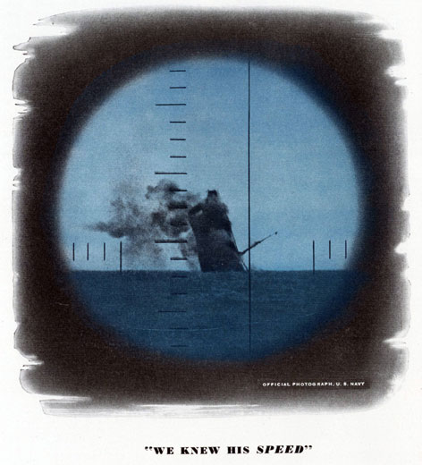
| We knew his speed |
Frontispiece |
| 1-1. |
Underwater log in position in submarine | 1 |
| 1-2. |
Elementary diagram showing fundamental principle of operation |
2 |
| 2-1. |
Components of Pitometer underwater log-rotary balance type |
5 |
| 2-2. |
Operation of Pitometer rotary balance system |
6 |
| 2-3. |
Operation of the master speed indicator |
Insert |
| 2-4. |
Cutaway view of rodmeter |
8 |
| 2-5. |
Rodmeter with valves attached |
8 |
| 2-6. |
Sea valve |
9 |
| 2-7. |
Rodmeter and hoist installed |
9 |
| 2-8. |
Control unit, cover removed |
11 |
| 2-9. |
Cutaway view of rotary distance transmitter |
13 |
| 2-10. |
Cutaway view of rotary pump |
15 |
| 2-11. |
Cutaway view of master speed indicator |
16 |
| 2-12. |
Cutaway view of speed and distance indicator |
18 |
| 2-13. |
Constant frequency control unit, cover removed |
20 |
| 3-1. |
Valves and vent cocks in secured position |
22 |
| 3-2. |
Valves and vent cocks in surface venting position |
22 |
| 3-3. |
Surface and submerged venting routines |
23 |
| 3-4. |
Valves and vent cocks in operating position |
24 |
| 3-5. |
Pump vent cock |
24 |
| 3-6. |
Rodmeter in secured position |
24 |
| 3-7. |
Valves and vent cocks operating on static head |
25 |
| 5-1. |
Vent cocks positioned to check clogged rodmeter |
32 |
| 5-2. |
Rodmeter in secured position |
34 |
| 5-3. |
Rodmeter with valves installed |
34 |
| 5-4. |
Cutaway view of Pitometer rodmeter |
36 |
| 5-5. |
Pump installed |
37 |
| 5-6. |
Removing impeller shaft lock nut |
37 |
| 5-7. |
Pump disassembled |
38 |
| 5-8. |
Impeller disassembled |
39 |
| 5-9. |
Checking length of rotary seal bellows |
39 |
| 5-10. |
Stretching rotary seal bellows |
39 |
| 5-11. |
Refacing rotary seal insert |
40 |
| 5-12. |
Pressing out rotary seal insert |
40 |
| 5-13. |
Installing rotary seal insert |
41 |
| 5-14. |
Checking rotary seal insert |
41 |
| 5-15. |
Cutaway view of rotary pump |
43 |
| 5-16. |
Checking impeller clearance |
44 |
| 5-17. |
Pump drive motor installed |
45 |
| 5-18. |
Removing upper brush |
45 |
| 5-19. |
Pump drive motor partially disassembled |
46 |
| 5-20. |
Removing transtat |
48 |
| 5-21. |
Removing follow-up motor |
49 |
| 5-22. |
Rectifiers installed |
49 |
| 5-23. |
Removing self-synchronous transmitter |
50 |
| 5-24. |
Valves in position for adjusting contacts |
52 |
| 5-25. |
External contact arm in center position |
52 |
| 5-26. |
End view of contact arm clamps |
53 |
| 5-27. |
Adjusting upper contacts by the lamp method |
54 |
| 5-28. |
Adjusting lower contacts by the lamp method |
54 |
| |
vi
|
| 5-29. |
Adjustable stop rods installed |
55 |
| 5-30. |
Setting upper adjustable stop rod, old installation |
56 |
| 5-31. |
Setting upper adjustable stop rod, new installation |
56 |
| 5-32. |
Control unit removed from case |
57 |
| 5-33. |
Pigtail wiring connection |
58 |
| 5-34. |
Bellows housing, cover removed |
58 |
| 5-35. |
Bellows installed on housing |
59 |
| 5-36. |
Cutaway view of seal bellows assembly |
59 |
| 5-37. |
Bellows housing assembly, old installation |
60 |
| 5-38. |
Bellows housing cover with housing end cap and stop rod removed, new installation |
61 |
| 5-39. |
Bellows housing cover assembled, new installation |
61 |
| 5-40. |
Bellows housing assembly |
61 |
| 5-41. |
End view of contact arm clamps |
62 |
| 5-42. |
Valve positions for aging the bellows |
62 |
| 5-43. |
Exploded view of bellows assembly |
63 |
| 5-44. |
Piping assembly, old installation |
64 |
| 5-45. |
Piping assembly, new installation |
64 |
| 5-46. |
Pressure relief assembly disassembled |
65 |
| 5-47. |
Cutaway view of master speed indicator |
66 |
| 5-48. |
Lead screw drive motor removed |
67 |
| 5-49. |
Replacing lead screw drive motor, Step 1 |
68 |
| 5-50. |
Replacing lead screw drive motor, Step 2 |
68 |
| 5-51. |
Replacing lead screw drive motor, Step 3 |
68 |
| 5-52. |
Master speed indicator, dial removed |
69 |
| 5-53. |
Slip ring and contact assembly, brush block removed |
70 |
| 5-54. |
Installing spiral take-up spring |
71 |
| 5-55. |
Removing follow-up contact assembly and top bracket |
72 |
| 5-56. |
Follow-up contact assembly removed |
72 |
| 5-57. |
Slip ring and contact assembly removed |
72 |
| 5-58. |
Lead .screw yoke assembly removed |
73 |
| 5-59. |
Master speed indicator, top mounting plate removed |
74 |
| 5-60. |
Lead screw and differential partially disassembled |
75 |
| 5-61. |
Roller shaft and pinion removed from yoke |
76 |
| 5-62. |
Pressing out short end of differential shaft |
76 |
| 5-63. |
Pressing out long end of differential shaft |
77 |
| 5-64. |
Installing bearing on short end of differential shaft |
77 |
| 5-65. |
Rear view of master speed indicator showing jack plug connections |
78 |
| 5-66. |
Removing friction disk and spider |
79 |
| 5-67. |
Constant speed motor removed |
79 |
| 5-68. |
Constant speed motor partially disassembled |
80 |
| 5-69. |
Worm gear housing assembly disassembled |
80 |
| 5-70. |
Distance repeating self-synchronous motor removed |
82 |
| 5-71. |
Self-synchronous repeater, brushes removed |
82 |
| 5-72. |
Self-synchronous repeater, damper assembly removed |
83 |
| 5-73. |
Checking shaft extension installation |
84 |
| 5-74. |
Speed transmitter driven gear removed |
85 |
| 5-75. |
Rotary converter |
86 |
| 5-76. |
Rotary converter, commutator shutter removed |
87 |
| 5-77. |
Rotary converter, collector ring shutter removed |
87 |
| 5-78. |
Rotary converter, speed regulator and one commutator brush removed |
88 |
| 5-79. |
Checking speed regulator contact point gap |
89 |
| 5-80. |
Rotary converter partially disassembled |
90 |
| |
vii
|
| 5-81. |
Constant frequency control unit, cover removed |
92 |
| 5-82. |
Phonic wheel motor and differential assembly installed |
94 |
| 5-83. |
Removing phonic wheel motor |
95 |
| 5-84. |
Phonic wheel motor disassembled |
95 |
| 5-85. |
Constant frequency control unit, main mounting plate removed |
97 |
| 5-86. |
Constant frequency control unit wiring diagram |
99 |
| 6-1. |
Pump orifice plate |
101 |
| 6-2. |
Measured mile course |
102 |
| 7-1. |
Shop calibration equipment |
105 |
| 7-2. |
Pressure tanks at zero position |
107 |
| 7-3. |
Dynamic pressure tank at 4-knot position |
108 |
| 8-1. |
Log wiring circuit diagram |
111 |
| 9-1. |
Lubrication points, rotary distance transmitter |
113 |
| 9-2. |
Lubrication points, rotary pump |
114 |
| 9-3. |
Lubrication points, constant frequency control unit |
114 |
| 9-4. |
Lubrication points, master speed indicator |
115 |
| 9-5. |
Lubrication points, speed and distance indicator |
116 |
| 9-6. |
Lubrication points, control unit |
116 |
| 10-1. |
The Bendix rodmeter |
118 |
| 10-2. |
Components of Bendix underwater log system |
119 |
| 10-3. |
Master transmitter indicator |
120 |
| 10-4. |
Operation of the master transmitter indicator |
Insert |
| 10-5. |
Speed and distance indicator |
121 |
| 10-6. |
Sea valve |
124 |
| 10-7. |
Rodmeter and hoist installed |
125 |
| 11-1. |
Distance transmitter load switch |
127 |
| 11-2. |
Maneuvering cocks and drain cocks in secured position |
127 |
| 11-3. |
Maneuvering cocks and drain cocks in venting position |
128 |
| 11-4. |
Maneuvering cocks and drain cocks in operating position |
128 |
| 11-5. |
Maneuvering cocks and drain cocks in drain position |
128 |
| 11-6. |
Maneuvering cocks and drain cocks positioned for filling hydraulic lines |
128 |
| 13-1. |
Maneuvering cocks and drain cocks positioned for operating on static head |
133 |
| 13-2. |
Maneuvering cocks and drain cocks in zero position |
133 |
| 13-3. |
C-adjustment assembly |
134 |
| 13-4. |
Maneuvering cocks and drain cocks positioned to check for clogged rodmeter |
134 |
| 13-5. |
Maneuvering cocks and drain cocks positioned for blowing out static line |
134 |
| 13-6. |
Maneuvering cocks and drain cocks positioned for blowing out dynamic line |
135 |
| 13-7. |
Maneuvering cocks and drain cocks positioned for blowing out both hydraulic lines |
135 |
| 13-8. |
Rodmeter and hoist |
136 |
| 13-9. |
Bendix rodmeter |
137 |
| 13-10. |
Cutaway of bellows assembly |
138 |
| 13-11. |
Bellows installation on master transmitter case |
139 |
| 13-12. |
Bellows assembly removed |
140 |
| 13-13. |
Removing bellows lower lock nut |
141 |
| 13-14. |
Bellows assembly, disassembled |
142 |
| 13-15. |
Dive error compensating mechanism |
143 |
| 13-16. |
Maneuvering cocks and drain cocks positioned for dive error adjustment |
143 |
| 13-17. |
Speed and distance indicator removed from case |
145 |
| 13-18. |
Rear view of speed and distance indicator |
146 |
| 13-19. |
Speed and distance indicator, dial removed |
147 |
| 13-20. |
Transformer wiring diagram |
148 |
| 13-21. |
Self-synchronous distance repeater removed |
149 |
| |
viii
|
| 13-22. |
End view of distance repeater |
150 |
| 13-23. |
Distance repeater partially disassembled |
150 |
| 13-24. |
Terminal block assembly partially disassembled |
151 |
| 13-25. |
Speed repeater partially disassembled |
153 |
| 13-26. |
Locating position of pointer hub handle screw |
154 |
| 13-27. |
Wiring diagram showing connections for setting speed repeater to electrical zero |
154 |
| 13-28. |
Counter drive worm assembly disassembled |
155 |
| 13-29. |
Master transmitter indicator removed from case |
156 |
| 13-30. |
Removing follow-up motor |
157 |
| 13-31. |
Replacing follow-up motor, Step 1 |
157 |
| 13-32. |
Replacing follow-up motor, Step 2 |
158 |
| 13-33. |
Rear view of master transmitter indicator |
158 |
| 13-34. |
Self-synchronous speed transmitter partially disassembled |
159 |
| 13-35. |
Differential assembly removed |
161 |
| 13-36. |
Differential assembly disassembled |
162 |
| 13-37. |
Constant speed motor removed |
164 |
| 13-38. |
Constant speed motor partially disassembled |
165 |
| 13-39. |
Reduction gear housing disassembled |
166 |
| 13-40. |
Removing power motor |
167 |
| 13-41. |
Power motor partially disassembled |
168 |
| 13-42. |
Power motor drive gear assembly removed |
168 |
| 13-43. |
Power motor drive gear assembly disassembled |
169 |
| 13-44. |
Condenser and resistor assembly removed |
170 |
| 13-45. |
Follower assembly removed |
171 |
| 13-46. |
Follower lead screw removed |
172 |
| 13-47. |
Follower, differential, and rheostat assemblies installed |
172 |
| 13-48. |
Rheostat removed |
175 |
| 13-49. |
Component frame assembly removed |
176 |
| 13-50. |
Component frame assembly partially disassembled |
176 |
| 13-51. |
Cam and bracket assembly removed |
177 |
| 13-52. |
Cam and bracket assembly disassembled |
177 |
| 13-53. |
Power motor transmission shaft assembly disassembled |
178 |
| 13-54. |
Main force arm removed |
179 |
| 13-55. |
Main force arm partially disassembled |
180 |
| 13-56. |
Auxiliary and main balance arm assembly removed |
181 |
| 13-57. |
Auxiliary and main balance arm partially disassembled |
182 |
| 13-58. |
Contact arm assembly removed |
184 |
| 14-1. |
Measured mile course |
186 |
| 14-2. |
Adjusting diagram for calibrating the Bendix log |
188 |
| 14-3. |
The A-adjustment assembly |
189 |
| 14-4. |
The B-adjustment assembly |
190 |
| 14-5. |
Weight arm attached to instrument |
190 |
| 14-6. |
Weight arm attached to instrument |
191 |
| 14-7. |
Adjusting diagram for recalibrating the Bendix log |
194 |
| 15-1. |
Shop calibration equipment |
198 |
| 15-2. |
Cam positioned prior to setting pointer to exact zero |
199 |
| 15-3. |
Balancing master transmitter indicator, Step 1 |
200 |
| 15-4. |
Balancing master transmitter indicator, Step 2 |
201 |
| 15-5. |
Contact arm and contacts installed |
202 |
| 16-1. |
Bendix log wiring diagram |
206 |
| 17-1. |
Lubrication points, master transmitter indicator |
208 |
| 17-2. |
Lubrication points, speed and distance indicator |
209 |
| |
ix
|
| 18-1. |
Components of mercury differential manometer underwater log system |
213 |
| 18-2. |
Front view of manometer and transmitter |
215 |
| 18-3. |
Installation of float and gear rack |
215 |
| 18-4. |
Transmitter, cover removed |
216 |
| 18-5. |
Sixty-cycle alternating current integrator timing assembly, cover removed |
217 |
| 18-6. |
Integrator cam at 15-knot and zero-knot positions |
218 |
| 18-7. |
Integrator wheel control mechanism |
219 |
| 18-8. |
Distance repeater contacts installed |
219 |
| 18-9. |
Master speed repeater, cover removed |
220 |
| 18-10. |
Master speed repeater, pointer and dial removed |
221 |
| 18-11. |
Heart cam, with roller in normal and abnormal positions |
222 |
| 18-12. |
Follow-up contact assembly operating positions |
223 |
| 18-13. |
Speed and distance repeater removed from case |
224 |
| 19-1. |
Venting routine, Step 1 |
225 |
| 19-2. |
Venting routine, Step 2 |
225 |
| 19-3. |
Venting routine, Step 3 |
225 |
| 19-4. |
Valves and vent cocks in operating positions |
226 |
| 20-1. |
Valves and vent cocks in position to check for clogged rodmeter |
227 |
| 20-2. |
Rodmeter |
229 |
| 20-3. |
Front view of gear chamber |
230 |
| 20-4. |
Adjusting fork |
231 |
| 20-5. |
Direct current clock integrator timer |
231 |
| 20-6. |
Distance repeater contacts adjustment |
231 |
| 20-7. |
Cam positioned for setting pointer at 22 knots |
233 |
| |
x
|