10A1. General. The Bendix Underwater
Log is made by the Bendix Aviation Corporation, Marine Division, Brooklyn, New York.
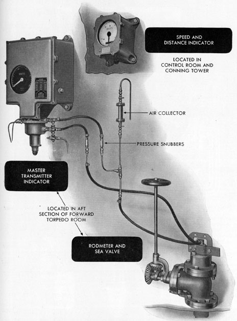
This system (Figure 10-2) consists of four
major components. Each instrument is watertight, and is designed for either panel or
bulkhead mounting.
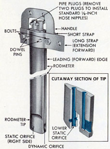
10A2. Rodmeter. The rodmeter (Figure 10-1), commonly called the sword, is located in
the forward torpedo room below the light
draft water line. It projects through the
hull of the ship, into the water, and is the
unit in which static and dynamic pressures
are produced and transmitted to the other
units of the system. When in use, the rodmeter extends about 3 feet into the water.
Being located in the forward part of the ship,
Figure 10-1. The Bendix rodmeter.
the rodmeter contacts water that is least affected by the movement of the ship or by the
turbulence of the water created by the action
of the propellers.
10A3. Sea valve. The sea valve and extension form a support for the rodmeter and
provide a means of closing the opening
through which the rodmeter passes when the
rodmeter is withdrawn, or fully housed. It
is located in a well below the deck in the
forward torpedo room, and is bolted to the
inner hull below the light draft water line.
A tube extends from the underside of the inner hull to the outer hull where it is welded
to a flange and guide bushing. The guide
bushing forms the lower support for the rodmeter. When the rodmeter is withdrawn, the
closing of the sea valve prevents sea water
from flooding the forward torpedo room.
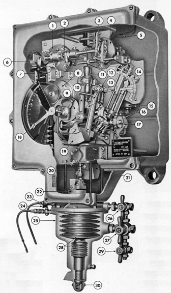
10A4. Master transmitter indicator. The
master transmitter indicator (Figures 10-3
and 10-4) is mounted inside the ship in the
forward torpedo room, 4 feet or more below
the light draft water line of the ship. The
instrument consists of electro-mechanical
linkages, known as the log mechanism,
mounted inside the case, and a bellows assembly mounted below the case. The bellows
assembly is divided into chambers. The upper
part of the bellows chamber is hydraulically
connected to the static tube in the rodmeter
by means of flexible hose and copper tubing.
The lower part of the bellows chamber is
connected to the dynamic tube in the rodmeter in the same manner. Flexible tubing
permits lowering the bellows assembly from
the case without disconnecting the tubing.
The movement of the bellows rod, caused by
dynamic pressure, actuates a spring-loaded
balance arm mechanism which develops the
force applied to equalize the dynamic pressure produced within the rodmeter. The
movement of the balance arm operates electrical contacts which control a main drive
118
Figure 10-2. Components of Bendix underwater log system.
119
1. SELF-SYNCHRONOUS DISTANCE TRANSMITTER
2. DIFFERENTIAL ASSEMBLY
3. FOLLOWER
4. ROTATING DISK
5. LEADS TO CONSTANT SPEED MOTOR
6. RHEOSTAT
7. FOLLOW-UP MOTOR (TORQUE AMPLIFIER)
8. SELF-SYNCHRONOUS SPEED TRANSMITTER
9. CAM
10. MAIN FORCE ARM
11. A ADJUSTMENT ASSEMBLY
12. AUXILARY BALANCE ARM
13. MAIN BALANCE ARM
14. B ADJUSTMENT ASSEMBLY
15. POWER MOTOR
16. CONTACT ARM ASSEMBLY
17. CONTACT ASSEMBLY
18. POINTER
19. MAIN FORCE ARM COUTNERWEIGHT
20. C ADJUSTMENT ASSEMBLY
21. MAIN BALANCE ARM COUNTERWEIGHT
22. ROTATING CONTERWEIGHT
23. STATIC DRAIN COCK
24. DYNAMIC DRAIN COCK
25. BELLOWS CHAMBER
26. STATIC MANEUVERING COCK
27. DYNAMIC MANEUVERING COCK
28. BELLOWS
29. DRAIN MANEUVERING COCK
30. DIVE ERROR COMPENSATING ASSEMBLY
motor. Through mechanical linkage a speed
pointer is turned to indicate the speed of
the ship in knots. This speed indication is
electrically transmitted to the speed and distance indicators, or repeaters. By means of a
controlled time element, the motion of the
mechanism is transposed from a speed indication to a distance indication, and this distance indication is electrically transmitted
to the repeaters where it is registered on a
six-place odometer, or counter. The log mechanism is mounted on a single brass plate
which permits the removal of the entire mechanism from the case as a unit. The case
and mounting plate are equipped with plug
and jack units so that electrical connections
need not be disturbed when removing the
mechanism from the case. The complete instrument is rubber shock-mounted.
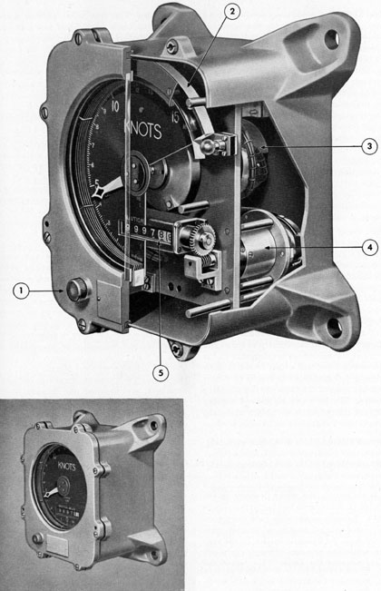
10A5. Speed and distance indicators. One of
the two speed and distance indicators (repeaters) (Figure 10-5) is mounted in the control room and one in the conning tower.
These units are housed in watertight cases
equipped with glass windows through which
the speed dials and the distance counters are
visible. Each unit consists of a speed repeating self-synchronous motor, and a distance repeating self-synchronous motor
which are connected electrically to speed and
distance self-synchronous transmitters in the
master transmitter indicator. Speed is indicated on a dial graduated in tenths of a knot
from 0 to 25 knots. The counter is a six-place
odometer. The first two right-hand number
wheels are colored white with black numerals,
and represent hundredths and tenths of nautical
miles. The four other number wheels
are colored black with white numerals, and
indicate nautical miles. A transformer is
mounted within the instrument to convert
the 115-volt 60-cycle current to a lower voltage for the lighting circuit. A six-position
tap switch is connected to the transformer
and permits the selection of variable voltage
to control the intensity of light for the instrument. Four lamps furnish illumination
which is carried around the dial by a ringlight.
10A6. Sea water lines. The water lines system consists of copper tubing, flexible rubber
tubing, an air collector, and two pressure
snubbers. The fixed tubing consists of 3/8-inch seamless copper tubing connected with
standard 3/8-inch flared-type screw connections that may be easily disconnected or replaced. Flexible rubber tubing is connected
at the rodmeter nipples to permit the raising
and lowering of the rodmeter. Flexible rubber tubing is also provided at the master
transmitter end of the fixed lines to permit
the lowering of the bellows assembly without
disconnecting the lines. An air collector is
mounted in the static line. The air collector
consists of a glass tube protected by a metal
casing, and is provided with two shut-off
valves. One shut-off valve is mounted at the
bottom of the air collector to control the
flow of water into the collector. The upper
shut-off valve permits the release of air from
the lines. Two pressure snubbers, or shock
absorbers, are mounted one in each line to
protect the bellows from any sudden shock
or increase in pressure due to an explosion
or a sudden surge of water.
B. DESCRIPTION OF OPERATION
10B1. Sea valve and rodmeter. While the
ship is stationary, the water pressure in the
rodmeter is static, and the log system is in
balance. As soon as the ship gets underway,
the forward motion creates additional pressure through the dynamic orifice in the rodmeter, while the pressure through the static
orifices remains the same. This creates an
unbalanced condition in the master transmitter
indicator, and causes it to operate
(Figure 10-4).
10B2. Operation of master transmitter indicator. a. Derivation of speed. As the ship
begins to move forward, the bellows rod rises
because of a pressure difference within the
bellows. The rod movement is transmitted
through the C-adjustment mechanism to a
pivot on the main balance arm, causing the
122
main balance arm to rotate to the right. The
contact arm mounted on the main balance arm
first closes the slow speed contact and then
the high speed contact, depending on whether
the acceleration is small or great. When
contact is made on the forward velocity side
of the contact assembly, the power motor
turns, and this action is transmitted through
the gearing and the transmission shaft assembly to a helical gear on the cam and bracket
assembly. The helical gear, cam, speed transmitter drive gear, and pointer are fixed to the
same shaft so that when the helical gear is
turned, the cam and pointer are also turned.
As the cam turns, it moves the cam follower
of the main force arm extension downward.
This action moves the main force arm and
causes the A-spring, attached at its upper
end to the main force arm and at its lower
end to the main balance arm, to stretch. When
the load on this spring just overcomes the
force of the bellows rod, the contact arm is
returned to its central, or neutral, position
and the power motor stops turning. When the
power motor stops turning, the cam, pointer,
and speed transmitter drive gear also stop
turning, thereby maintaining this set position
of the cam and pointer assembly until the
ship changes speed. The speed transmitter
drive gear is geared to the speed transmitter
driven gear in such a relation that a 240-degree turn of the pointer in the master transmitter indicator will turn the pointers in the
speed and distance indicators 360 degrees,
thereby transmitting speed indications to
the speed and distance indicators. In addition
to driving the cam assembly, the power motor
transmission shaft assembly also drives a lead
screw in the component frame assembly which
positions the B-adjustment slide downward
from the zero position. When the B-adjustment pointer is turned away from zero on the
scale, the motion of the slide moves the auxiliary balance arm which causes the B-spring
to stretch between the auxiliary balance arm
and the main balance arm. This B-spring aids
the A-spring in overcoming the force of the
bellows rod and in returning the contact arm
to its neutral position.
b. Derivation of distance. The lead screw
in the component frame assembly is geared to
the lead screw in the follower assembly. The
follower assembly lead screw positions the
follower radially across the rotating disk.
The rotating disk, driven by the constant
speed motor, is turning at a constant speed or
60 rpm. The position of the follower on the
disk is dependent on the pointer indication,
or speed indication. The follower is caused to
turn by the rotation of the disk and, by its
position on the disk, turns at the rate of 360
revolutions per nautical mile. The follower,
through the universal joint, therefore, turns
the right-hand side of the differential at 360
revolutions per nautical mile. Since the
torque required to drive the distance transmitter is greater than the torque that can be
obtained from the follower, a torque amplifier
is used. The torque amplifier (follow-up
motor) consists of a shaded pole induction
motor, rheostat, slipping clutch, differential,
and suitable gearing. The shaded pole induction motor (follow-up motor) turns the distance transmitter and the left-hand side of the
differential. If the left-hand and right-hand
sides of the differential turn at different
speeds, the spider rotates in the direction of
the faster moving differential gear, and turns
the rheostat brush arm through a slipping
clutch. This action changes the voltage across
the main field of the follow-up motor. The
change in voltage changes the torque which
the motor can supply, thereby changing its
speed so that the distance transmitter rotates
at the same speed as the follower and disk,
that is, at 360 revolutions, per nautical mile.
The self-synchronous distance transmitter
transmits the distance indications to the speed
and distance indicators.
10B3. Speed and distance indicators (repeaters). The speed and distance indications of
the master transmitter indicator are electrically transmitted to the mechanism in the
speed and distance indicators, and are registered on the dial and counters of those units.
123
C. RODMETER AND SEA VALVE
10C1. Rodmeter. The Bendix rodmeter
(Figure 10-1) is made of manganese bronze,
and is approximately 8 feet long. This length
is necessary in order that the rodmeter may be
projected through the inner and outer hulls
of the submarine. It has a streamline cross-section, with a flat tip at its lower end. Two
water passages are formed in the rodmeter;
the upper ends of these passages terminate in
tapped openings, protected by pipe plugs.
Standard pipe fittings are installed in these
tapped openings in order that the flexible
hose may be attached to the rodmeter. The
lower end of the forward passage in the rodmeter terminates in an opening in the forward
edge, called the dynamic orifice. The lower
end of the after passage terminates in three
openings, one on each side of the tip and one
in the bottom of the tip. The latter openings
are called the static orifices. A handle and
two straps are mounted at the top of the rodmeter to serve as a means of raising and
lowering the rodmeter. When lowered, the
rodmeter projects about 3 feet through the
outer hull into the water. A lifting device is
provided in the ship for raising and lowering
the rodmeter and for replacing it in the event
of damage. The rodmeter must always be
raised, or housed, when the submarine docks
or when, for tactical reasons, the submarine
rests on the ocean floor.
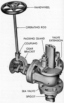
10C2. Sea valve. The sea valve assembly
(Figure 10-6) supports the rodmeter when the
rodmeter is projected into the sea, and prevents water from entering the ship when the
rodmeter is removed. The valve is a 3-inch
gate valve, operated by a handwheel on an
operating rod which in turn is bevel-geared
to the valve stem. The sea valve is bolted to
the inner hull of the ship. A valve extension
with packing gland is mounted to the top
flange of the valve. This extension provides
an upper support when the rodmeter is projected into the sea, and also provides a leakproof gland around the rodmeter.
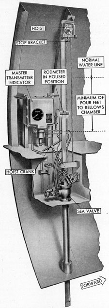
10C3. Rodmeter hoist. Submarines are
equipped with either one of two types of rodmeter hoists (Figure 10-7) for raising and
lowering the rodmeter. One type consists of
a single sprocket and chain arrangement, and
the other type is a double sprocket and chain
assembly. The upper sprocket is mounted
either on the side of the hull or on a suitable
panel near the rodmeter. The lower sprocket
is mounted in the well containing the sea
Figure 10-6. Sea valve.
valve. The sprockets are connected by a roller
chain. Operation is by means of a hand crank
through a worm gear drive. The roller chain
is connected to the strap and handle assembly
of the rodmeter by means of a connecting
link which is pinned to the chain and to the
strap and handle assembly. As the hand crank
is operated, the chain rotates around the
sprockets, thereby raising or lowering the
rodmeter. The hoist crank normally is stowed
in brackets near the sea valve. To operate
124
Figure 10-7. Rodmeter and hoist installed.
125
the hoist, a deck plate must be raised and the
crank lifted off its brackets and placed on
the hoist operating rod. When in the lowered
or operating position, the straps on the upper
end of the rodmeter are close to the top of the
sea valve extension gland. Approximately
32 turns of the crank are required to raise the
rodmeter to the normal housed position, that
is, the position that permits the tip just to clear
the outer hull. In this position, approximately
half the length of the rodmeter is above the
sea valve extension. This point is usually
marked by a plate mounted on the side of the
hoist bracket. The rodmeter is fully housed
when the tip clears the sea valve gate. Approximately 82 turns of the crank are required
to raise the rodmeter to the fully housed position. The sea valve should then be closed.
About eight additional turns are required to
raise the rodmeter to its extreme secured position for inspection. Care should be exercised
when lowering the rodmeter from this latter
position to see that the packing is not pushed
out of the gland.