C.F. 'O' Class Submarines - Oil Fuel Systems, describes the fuel systems of the Oberon class submarines.
In this online version of the manual we have attempted to keep the flavor of the original layout while taking advantage of the Web's universal accessibility. Different browsers and fonts will cause the text to move, but the text will remain roughly where it is in the original manual. In addition to errors we have attempted to preserve from the original, this text was captured by a combination of optical character recognition and human typist. Each method creates errors that are compounded while encoding for the Web. Please report any typos, or particularly annoying layout issues with the Mail Feedback Form for correction.
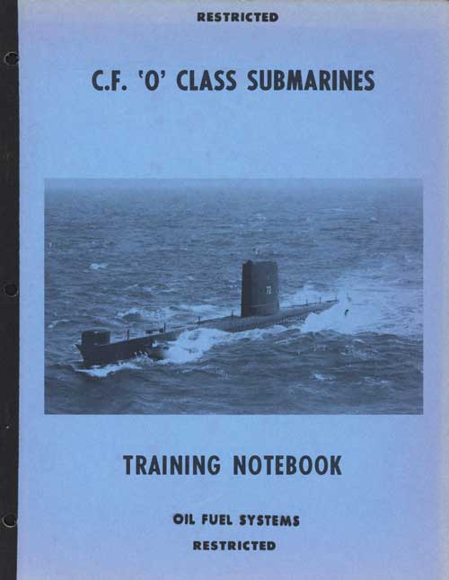
Fuel oil for the engines is normally carried in 8 external, 1 internal and Nos. 3 and 5 M.B. tanks giving
a total capacity of approximately 100,000 gallons. The
external tanks are arranged in 4 groups, the tanks comprising each group being connected in sequence by syphon pipes. These pipes extend from the top of the foremost tank in each forward group, and from the aftermost tank in each after group, to within 2 in. from the bottom of the next tank.(Fig 1)
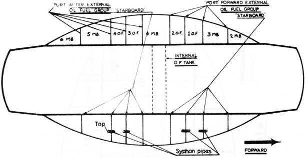
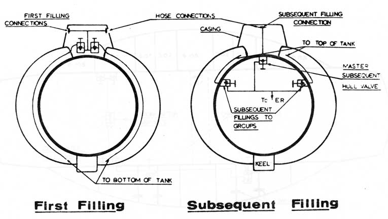
Before fuel is embarked, the storage tanks are completely filled with sea water to expel air. This operation is termed 'first filling'. (Fig 2 & 4)
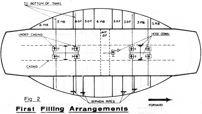
After the first filling is completed the tanks are filled with fuel which displaces the water. This operation is termed 'subsequent filling'.(Fig 3 & 4)
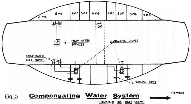
Fuel for the engines is normally displaced by sea water admitted through a compensating water system, thus assisting in maintaining the trim of the submarine. The compensating water is supplied at a pressure of 5-10 p.s.i. from the after services or the engine seawater cooling
system. (Fig 5)
De-fuelling is accomplished by admitting compensating water or reduced H.P. air into the groups and internal tank.
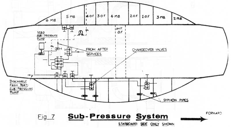
To prevent leakage of fuel into the sea, should an external tank develop a small leak, a sub-pressure system is provided, the function of which is to maintain pressure
within the tank at just below that of the sea. Thus, sea
water will enter a damaged tank instead of fuel flowing out (Fig 7)
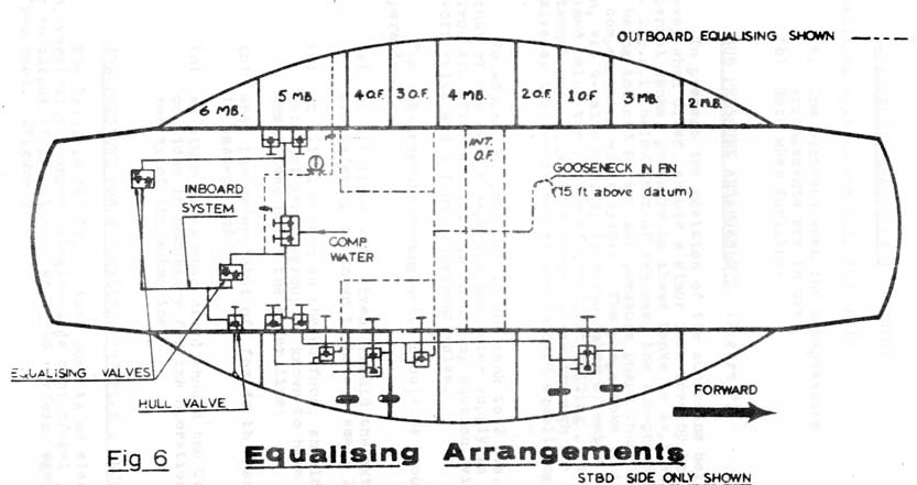
To safeguard the structure of the lightly built external tanks from damage, which could occur through excessive internal or external pressure created when the submarine changes depth, tank equalising arrangements are provided. (Fig 6)
7-3
Oil Fuel Tank Layout Fig 1
7.02 FUEL DISPLACEMENT (Fig 5)
Compensating water is delivered to the bottom of the foremost tanks of the forward groups and to the aftermost tanks of the after groups, and also to the internal tank, the fuel being displaced in the case of the external group through the syphon pipes until fuel in a particular group is expelled. From the last tank of the group the fuel passes to the engines via the common subsequent filling line, a Centrifuge or Lolos strainer and a gravity tank. The fuel in the internal tank is displaced direct to the common subsequent filling line. A 15 p.s.i. sea relief valve is fitted in the compensating water system, and a 35 p.s.i. relief valve in the compensating water line to the internal tank, To enable the supply of compensating water to Nos. 3 and 5 M.B. Tks. to be shut off without interfering with the supply to the remaining tanks of their associated group, two double-seated change-over valves are provided, one pair forward the other pair aft in the compensating water lines within the keel. The valves are worked from inboard. Stop valves are also fitted in the syphon pipes leading from Nos. 3 and 5 M.B. Tks, to the next tanks of their associated groups.
7-4
7-5
7-6
7-7
7-8
7.02 FUEL DISPLACEMENT (CONTD)
Note: When snorkelling using an external group, the fuel is displaced by compensating water admitted direct from sea through the equalising arrangements.
7.03 EQUALIZING ARRANGEMENTS (Fig 6)
For the adjustment of pressure differences
which occur between the inside and outside of the external tanks when the submarine changes depth two separate
equalising systems are provided. Both systems are connected to the compensating water system and are normally operated in conjunction with one another.
A. Outboard System
Consists of an open ended header pipe sited within the bridge fin and extending 15 ft. above the datum line, joined to an expansion pipe run along the top of the pressure hull, the expansion pipe being connected by shut-off valves to the compensating water lines of the four external groups. The shut-off valves are operable from inboard and are normally kept lashed open.
B. Inboard System
The function of this system is automatically to open the external groups to sea should the pressure within them fall outside a range of between 5 p.s.i. above and 3 p.s.i. below the sea pressure. The system comprises two equalising valve chests, one for the port and one for the starboard external groups, connected to the compensating water system, and, each via a stop valve, to a common hull valve.
Each valve chest houses two opposed spring-loaded non-return valves which are set to lift, one when the tank pressure exceeds that of the sea by 5 p.s.i., and other when the sea pressure exceeds that of the tank by 3 p.s.i. Thus the tanks are open to sea at all depths should the pressure within them fall outside this range.
7-9
Fig 6 Equalising Arrangements
7-10
7.03 EQUALISING ARRANGEMENTS (CONTD)
The equalising systems are only shut off:
(a) The outboard when sub-pressure arrangements are in use.
(b) Both when fueling.
7.04 SUB PRESSURE ARRANGEMENTS (Figure 7)
To prevent the position of the submarine being given away when dived, should a minor leak develop in the external tanks, pressure in these tanks is kept at approx. 2 p.s.i. below that of the sea, the sub-pressure effect being induced by two sub-pressure pumps connected to the compensating water system. The pumps take their suction, vis 4-valve chests, from the layer of water maintained below the bottom of the first filling pipes in the external groups, and discharge to see through the same hull valve as that which serves the inboard equalising system.
To adjust the pressure in the tank to 2 p.s.i. below that of the sea, a separate sea water supply is taken from the after services to each pump suction, vis a shut-off valve and a fine adjustment valve.
The sub-pressure arrangements should be brought into operation:
(a) at all times when dived, should the external groups/group be known to have a small leak;
(b) at all time when on the surface, should the external groups/group be known to have a small leak below the water line;
(c) when the order 'shut off for depth charging' is pressed; and
(d) at other times when dived should the Captain consider it necessary for the operational safety of the submarine.
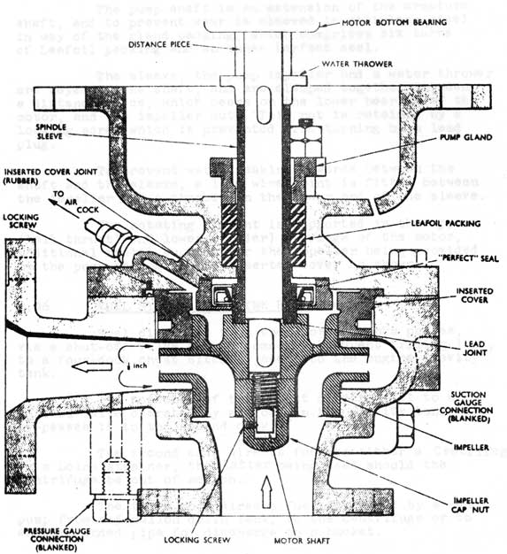
7.05 SUB-PRESSURE PRUMPS (DRYSDALE 'W' TYPE 2 INCH)
The Drysdale 'W' Type 2 inch pump is an electronically-driven, vertically mounted, single-stage centrifugal pump, having an output of 10 gal/min. at 1,340 rev/min. against a 10 foot head. (Figure 9)
7-11
Fig 7 Sub-Pressure System
7-12
Fig 8
SUB-PRESSURE PUMP
7-13
7.05 SUB-PRESSURE PUMPS (DRYSDALE 'W' TYPE 2 INCH) (CONTD)
The pump is bolted to the underside of the motor casing, the latter being resiliently mounted (4-75 lb. type 'L' mountings) on a bracket attached to the ship's structure.
The pump shaft is an extension of the armature shaft, and to prevent wear is sleeved in stainless steel in way of the gland packing, which comprises six turns of Leafoil packing and an inner Perfect seal.
The sleeve, the pump impeller and a water thrower are keyed to the shaft, and are clamped together between a distance piece, which bears on the lower bearing of the motor, and the impeller nut. This nut is retained by a looking screw which is prevented from turning by a lead plug.
To prevent water leaking upwards between the shaft and the sleeve, a lead wire joint is fitted between the impeller and a chamber on the lower end of the sleeve.
The rotating element is supported in the upper (ball thrust) and lower (roller) bearings of the motor, additional radial support for the impeller being provided by the pump casing and an inserted cover as shown.
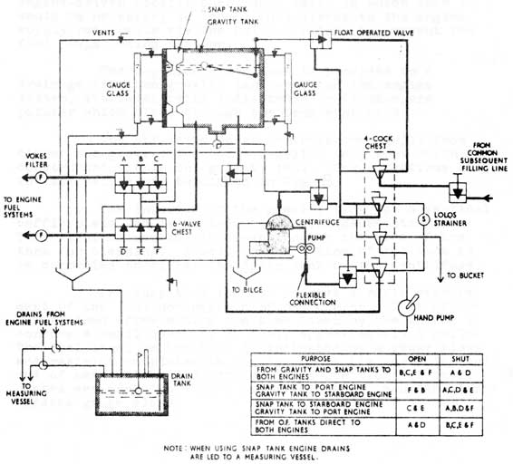
7.06 FUEL SYSTEM IN ENGINE ROOM (Fig 8)
Fuel displaced from the storage tanks passes, via a shut-off valve on the common subsequent filling line, to a four-cook chest sited adjacent to the engine gravity tank.
The top cock of this chest directs fuel to a control valve operated by a float in the gravity tank, or by-passes it to the second cock.
The second cock directs fuel to either a Centrifuge or a Lolos strainer, the latter being used should the Centrifuge be out of action.
The third cock directs fuel delivered by a hand pump from a 5-gallon drain tank, to the Centrifuge or to an open-ended pipe for discharge to a bucket.
7-14
Fig 8. FUEL SYSTEM IN ENGINE ROOM
7-15
7.06 FUEL SYSTEM IN ENGINE ROOM (CONTD)
The bottom cock directs the Centrifuge or Lolos strainer discharges to the gravity tank or a six-valve chest, the latter connection being only used should the engine-driven booster pump/pumps fail, in which case it would be necessary to 'comp' fuel direct to the engine supply rail/rails via the Lobos strainer to prevent the fuel pumps losing suction.
The 5-gallon drain tank is provided to collect drainage from the gravity tank vent end the engine drain system, its level being indicated by a float-operated pointer which rises through the tank vent pipe.
The six-valve chest controls the supply from either the gravity tank or a 2-gallon snap tank which is constructed within the gravity tank. The operations of the six valves are tabulated in Fig. 8.
The interior of the gravity tank has a vertical baffle plate and is fitted with a wire gauze strainer. This strainer can be withdrawn through the side of the tank for cleaning. A well on the bottom of the tank can be connected to either the drain tank or the Centrifuge.
The snap tank is used to give a rapid measurement of the fuel consumption of one engine. This can he ascertained after noting the time taken by the engine to consume a small quantity of fuel, approximately 1 gallon. The fuel level in the tank is indicated by a gauge glass and restriction plates in the tank mark the beginning and end of each calibrated section. The positions of these plates are marked of on a level indicator, mounted alongside the gauge glass.
7-16
Large Plate on Separate Page
Oil Fuel System Fig 17