C.F. 'O' Class Submarines - Electrical Systems, describes the electrical systems of the Oberon class submarines.
In this online version of the manual we have attempted to keep the flavor of the original layout while taking advantage of the Web's universal accessibility. Different browsers and fonts will cause the text to move, but the text will remain roughly where it is in the original manual. In addition to errors we have attempted to preserve from the original, this text was captured by a combination of optical character recognition and human typist. Each method creates errors that are compounded while encoding for the Web. Please report any typos, or particularly annoying layout issues with the Mail Feedback Form for correction.
To supply power whilst not generating for ships various systems. To have the ability to absorb (charging), store and deliver (discharging) electrical power.
11.01 BATTERY COMPARTMENTS
The battery compartments are used as containers for the batteries. There are two compartments: #1 - situated under accommodation space and #2 - situated under Control Room (forward).
The steel deck, bulkheads and deckheads are lined with rubber to protect them against the corrosive effect of spilled acid and acid spray. To protect battery maintainers from
electric shock, all fixtures within compartment are either made of an insulated material or coated with an insulating material.
The wooden gratings, which make up the deck and the side barriers of a battery compartment are made of teak and are resiliently mounted to give the battery protection against mechanical shock and vibration. The gratings are impregnated with paraffin wax to reduce the damaging effect of battery acid.
To prevent movement of cells in rough seas and radical underwater maneuvers, wooden wedges are driven vertically between certain cells so all cells are solidly wedged against one another and the compartment bulkheads. These wedges are usually placed in two rows athwartships and two rows fore-and-aft.
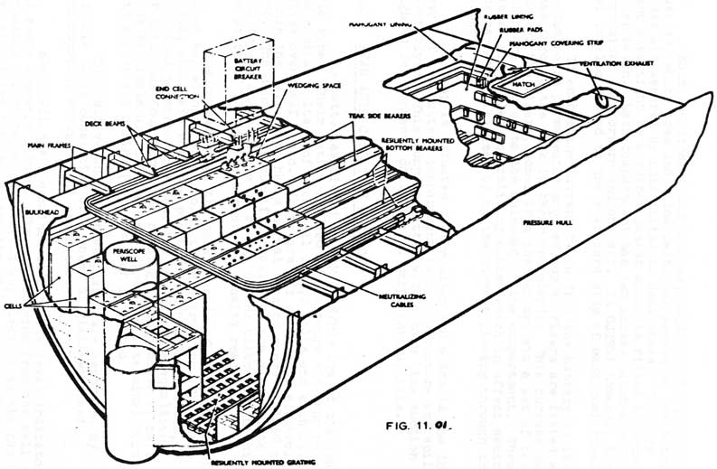
The arrangement of a typical battery compartment shows cells installed at various levels. The cells elevated are the outboard row on either side in "P" & "O" class submarines, not the two outboard rows as shown. This arrangement provides increased space between the cell top and the deckhead above the centre cells. Wooden platforms, called crawling boards, running fore and aft and inter-connected by an athwartship platform enable personnel to inspect and service the cells. These
crawling boards are supported by struts bolted to deckhead and are placed over cells which are not elevated.
11-2
Battery compartment - typical arrangement.
11-3
Each compartment has hatches, called battery access hatches, which open and allow personnel access to the battery. These are secured by nuts fitted to deck studs. They are kept watertight by a rubber gasket which is fitted to deck under hatch. Each compartment has two access hatches on its port side; one forward and one aft. In OJIBWA however, another set is also fitted to the starboard side of each compartment.
To enable the current to go from the battery to it's switch board permanently mounted copper risers are fitted which pass through the deck in their own glands. This current passing through the risers, comes from the battery via a set of cables which are secured to the bulkhead of the compartment. These cables are called neutralizing cables which in effect neutralize the magnetic field set up by the current flowing through the battery.
A sump is situated at the after end which is the lowest level of the battery compartment to catch moisture and spilled electrolyte. This sump is fitted with a main line suction and is sighted for contents daily i.a.w. ships instructions.
11.02 LEAD ACID CELL TYPE D 7420
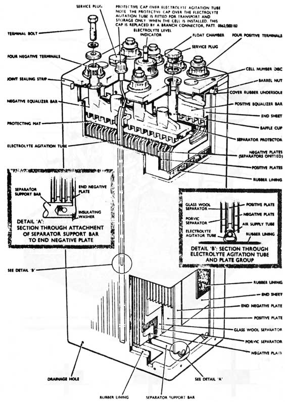
The batteries fitted in H.M.C. S/M's are of the lead acid type. Their rating is 74.20 ampere-hours @ 5 hour rate. The nominal voltage of each cell is 2.2 volts and each cell weighs over half a ton. There are 18 1/2 gallons of electrolyte within the cell which has a normal density range of 1080 to 1280. The density or specific gravity of the electrolyte will depend on the state of charge of the battery. The higher the state of charge the higher the density reading.
The container of the cell is made of fibre glass with a rubber bag within, which holds the electrolyte. The lead plates, which are both the positive and negative plates, are joined together on a positive and negative equalizing bar which has four terminals passing through cover of cell. These terminals are drilled and tapped and a terminal bolt with a flat and spring (lock) washer is fitted.
The positive and negative plates are separated by a double layer consisting of a sheet of glass wool and a microporous Porvic (PVC) separator.
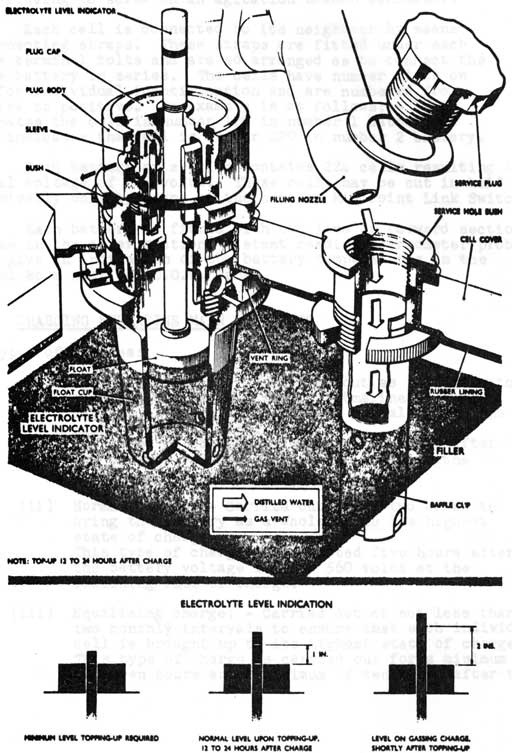
Each cell has a combined electrolyte level indicator and spray arrestor fitted. The gas escaping from the cell passes through a labyrinth which collects any electrolyte the gas may have and drains this back into the cell.
11-4
Cut-away view of cell, of Chloride manufacture, with electrolyte agitation.
Fig. 11.02
11-5
Details of electrolyte level indicator in plug and float chamber, and service hole bush.
Fig. 11.03
11-6
Each cell has an electrolyte agitator fitting which consists of a small tube which runs to the bottom of the cell and a fitting to screw on an agitation branch connector.
Each cell is connected to its neighbour by means of connecting straps. These straps are fitted under each of the terminal bolts and are so arranged as to connect the entire battery in series. The cells have number discs on them for individual identification and are numbered from negative to positive. An example is as follows: - 1/120 designates the cell is number 120 in number 1 battery as 2/220 indicates the cell is number 220 in number 2 battery.
Each battery or section contains 224 cells resulting in a nominal voltage of 440 volts. These cells may be cut in half electrically only by means of the battery Mid Point Link Switch.
Each battery is fitted with two (one in forward section and one in the after section) distant reading thermometer probes. These give an indication of the battery temperatures in the Control Room near the O.O.W. Panel.
11.03 CHARGING SUBMARINE MAIN BATTERIES
A. Types of Charges:
(i) Operational charge: -Carried out as necessary to recharge the battery so the submarine will be capable of operational duties; normally done the night before sailing.
This type of charge is completed one hour after the battery voltage reaches 560 volts at the finishing rate of charge.
(ii) Normal charge: - Carried out every two weeks to bring the battery as a whole up to its highest state of charge.
This type of charge is completed five hours after the battery voltage reaches 560 volts at the finishing rate of charge.
(iii) Equalizing charge: - Carried out at not less than two monthly intervals to ensure that each individual cell is brought up to its highest state of charge. This type of charge is carried out for a minimum of seven hours and a maximum of ten hours after the
11-7
battery voltage has reached 560 volts at the final rate of charge. However the charge may be broken at any time between these specified times if:
a. Nine half hourly readings of the overall battery voltage corrected to 80 degrees F do not vary.
b. Three half hourly density dips have not varied by more than two points.
B. Rates of Charges:
Initial charging rate with the battery density below 1180 is 1650 Amps Each Battery.
Initial charging rate with the battery density above 1180 is 1250 Amps Each Battery.
The finishing rate of charge is 280 Amps Each Battery.
C. Voltage During Charges:
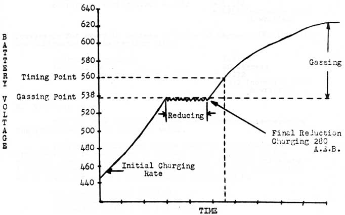
The initial rate of charge will depend on the battery density on starting the charge. As the battery is charged, the battery voltage will rise. When the battery voltage reaches the Gassing Voltage (538 V), the charging rate will be reduced slightly as necessary to maintain the voltage constant at 538V (or slightly below). This is called Reducing Finishing rate and is continued until the charging rate is reduced to the Finishing Rate (280 A.E.B.). The OOW is to be informed by the electrician on watch when he begins Reducing. The battery shall never be charged below 280 A.E.B.
When the charging rate has been reduced to 280 A.E.B., the battery voltage will begin to rise once more. As 538V is the Gassing Voltage, the battery will now begin to gas, (give off hydrogen) as the charge continues. Whenever the battery is gassing and for one hour after completing a charge during which tie the battery has been gassing, there shall be "no smoking". This is due to the danger of an explosive mixture of hydrogen and oxygen possibly being present during the gassing period.
The method of charging described is called Constant Voltage Reduction. This is the most efficient method of
charging and is the type carried out in CAF "O" class submarines.
11-8
Graph showing resulting voltage during a
Constant Voltage Reduction method of charging
In emergencies, the C.O. may order higher charging rates, but he alone may order this rate. It could be as high as 2000A/battery or the maximum he can get from the generators at the time.
11.04 TEMPERATURE CORRECTIONS
A Density:
The hydrometer used in the submarine is corrected to the standard temperature of 60 degrees F. When a dip is taken at this temperature the reading is true. However at any other density it would not read true and the reading must be corrected for temperature.
11-9
This is done by: - for every 10 degrees F. above 60 degrees F. .004 (4 points) are added to the reading taken e.g.
hydrometer reading
1.24.0
temperature
90 degrees
corrected reading 1.240 + .012
= 1.252
= 1252 (normally read & written)
Conversely for every 10 degrees F. below 60 degrees .004 (4 points) are subtracted to the reading taken
hydrometer reading
1.210
temperature
40 degrees
corrected reading 1.240 - .008
= 1.232
= 1232 (normally read & written)
B. Voltage:
For the same state of charge the higher the temperature the lower the voltage and vice versa.
During an equalizing charge when the constant voltages are needed it is necessary to correct these readings to the standard temperature of 80 degrees F. (add .68 volts for every 1 degree above 80 degrees F.). However for easier computation add 2 volts for every 3 degrees above 80 degrees F.
Voltage indicated
590 Volts
Temperature
92 degrees F.
Corrected voltage
590 + 8 = 598 volts
Conversely:
Subtracting from the voltmeter .68 volts for every 1 degree below 80 degrees F. or 2 volts for every 3 degrees below 80 degrees F.
Voltage indicated
590 Volts
Temperature
65 degrees F.
Corrected voltage
590 - 10 = 580 volts
11.05 QUARTERLY DISCHARGE
The main batteries are seldom completely discharged under ordinary conditions but unless this is carried out at regular intervals the effective capacity may be temporarily reduced.
At intervals not greater than four months after first being given a normal charge the battery must be given a discharge at the five hour rate until the final specified minimum voltage is reached. When the density of the battery falls to 165
points below the level reached at the end of the last equalizing
charge, the conditioning discharge may be postponed for one month, but should be carried out at the first available opportunity.
11-10
The five hour rate is 7420 Ampere/hours (the rating of the battery divided by 5 hr. rate) 7420/5 = 1485 Amps Each Battery
Upon completion of the discharge the battery must be given an equalizing charge or harmful effects to the battery will occur if it is allowed to lay in a discharged state.
The battery density must never be allowed to fall below 1080 or harmful effects will occur.
11.06 BATTERY VENTILATION
Battery ventilation is needed to ventilate the
battery compartments of gasses (hydrogen, in a 4% mixture is considered an explosive mixture) which are given off by the cells at all times. The amount will vary due to the amount of current flowing, temperature, age and voltage. It is also used to help in keeping battery cool if needed.
A. Battery ventilation is to be running for the following:
When floating the load
Charging the batteries
Snorkelling
Quarterly Discharge
Battery temperature above 115 degrees F
Maintainers in the battery compartments
Daily in harbour during morning and evening usually to tie in with battery dips and rounds @ 0800 and 2000
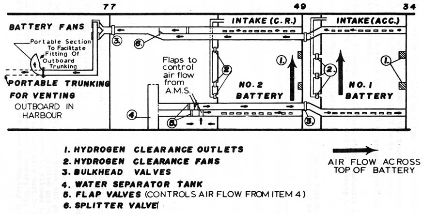
B. System Components (SS73 & 74)
Two battery ventilation fans with control "ON" "OFF" switches on Auxiliary Power Panel in Motor Room. Fans located in snake pit. Six hydrogen clearance fans, 3 in Cox'ns stores -3 in AMS, with control switches on the O.O.W. panel.
Two main intake flaps in AMS for battery fans. One intake and two exhaust flaps for the hydrogen clearance fans above each battery compartment.
Re-circ flaps for battery fans to enable air to come from 'S' tank instead of A.M.S. when passing through a fallout area snorkelling.
Bulkhead sluice valves. Two on 49 bulkhead for number one battery and one on 77 bulkhead for the main trunking.
11-11
BATTERY VENTILATION
S.S. 73 & S.S. 74
FIG. 11.04
11-12
These valves may be controlled on either side of the bulkhead.
A flap valve in the AMS on the trunking enables the outgoing air from number two battery to be shut off.
A splitter valve in the AMS to ensure equal air flow from both battery systems.
Portable trunking fitted where system exhausts in the engine room to be fitted whilst charging and gassing in harbour.
C. Opening up Battery Ventilation (SS73 & 74)
The battery ventilation system is run so that either the main ventilation fans or the hydrogen clearance fans are running at all times.
The normal situation is, unless charging, to have the hydrogen clearance fans running. To start the main battery fans:-
The hydrogen clearance fans (6) are switched off at the O.O.W. panel.
The one intake and two exhaust flaps for the hydrogen clearance fans of each battery are shut.
The three bulkhead sluice valves and the intake flaps in the A.M.S. are checked open.
The battery fans are started in motor room.
The air flow is checked with a piece of paper at the intakes in the A.M.S.
This step must be done in order to check both batteries are getting air flow across them.
To revert to normal state after finishing charge:
the battery fans are stopped.
the hydrogen clearance intake and exhaust flaps are opened.
the hydrogen clearance fans are then switched on.
Battery ventilation is run for one hour after a charge has been completed to make certain the battery compartment has been completely cleared of gasses.
Salt water entering a battery compartment and going into a cell will mix with electrolyte and chlorine gas will be given off. Therefore salt water must never be allowed to enter the battery compartment. Particular care must be taken when securing the battery access hatches to ensure they are watertight (i.e. all bolts tightened down and holding properly.).
11-13
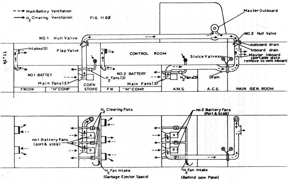
D. System Components (SS 72)
Four battery ventilation fans - two in cox'ns stores, two in AMS - with control switches for two fans fitted to each battery controlled on auxiliary control panel. Each switch electrically connects two fans in series to start which is the slow speed or "group down" and when the fans are running their switches are changed over to "parallel" which is full speed or "group up". They are run group up at all times during charges.
Six hydrogen clearance fans, 3 in cox'ns stores - 3 in AMS, controlled by switches on O.O.W. panel.
Two hydrogen clearance intakes - one situated above each battery compartment. The exhaust ports for this system are the intakes for the battery fans.
Two intake ports and flaps in accommodation space for number one battery and three intake ports and flaps in Control Room for number two battery.
No hull and two flap valves with an inboard and outboard drain fitted to each pair.
Master inboard flap valve open when master outboard is shut and ventilation is running inboard. The ventilation system is always opened inboard at sea.
Master outboard valve open when the master inboard is shut so ventilation can run outboard whilst charging alongside.
One bulkhead sluice valve on the engine room bulkhead. This valve may be controlled from either side of the bulkhead.
E. Opening up Battery Ventilation (SS 72)
The normal state of the battery ventilation whilst not charging is the hull valves shut, flap valves shut, ether master inboard open and master outboard shut or vice versa, the natural intakes open (they are only shut in emergency or fire in the battery) the hydrogen clearance intakes open, the bulkhead sluice valve open and the hydrogen clearance fans running. To open up the main vent fans the following is
carried out:-
Going to number two battery hull valve (in the engine
room) first (if any water in external trunking it won't go into battery) and open the outboard drain.
If and when no water flows, open the inboard drain. If clear,
Crack open the hull valve. If and when no water flows,
11-14
Main battery and hydrogen clearing ventilation
11-15
Fully open the hull valve.
When sure trunking is dry open the flap valve and shut the inboard and outboard drains.
Switch off hydrogen clearance fans whilst passing through control room and shut their intake flaps.
Go to number one battery hull valve and do the same routine as done for number two battery hull valve.
When opened up switch battery fans to series position. When indicator lights come on for all four fans switch over to parallel position and then check air flow at natural intakes for each battery.
To revert to the normal state with the hydrogen clearance fans running:-
Stop all battery fans and shut the hull and flap valves for both batteries.
Open the intake flaps for the hydrogen clearance fans. Switch on the hydrogen clearance fans.
Battery ventilation must be opened up and running before a charge may be put on. Thus no charging may be carried out with battery ventilation not running. If whilst charging the battery fan indication lights go out the charge must be broken and the defect rectified before the charge may be started anew.
F. Hydrogen Eliminators
While the hydrogen clearing fans are clearing the
battery compartment they are causing a buildup of hydrogen in the vessel. To combat this hydrogen eliminators are placed near the deckheads in each compartment. Compartments above battery compartments have four eliminators while other compartments have only one fitted.
The principle of the eliminator is it combines the hydrogen with oxygen in the air on the surface of a catalyst, which forms water. The water in turn is heated by a heater within and is given off as a vapor.
11-16
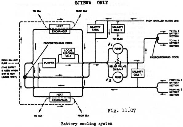
11.07 BATTERY COOLING
Battery cooling is needed to take the excess heat from the batteries caused by charging and discharging. It is designed to take the heat away from each cell and keep it within the workable limits of 80 degrees F to 110 degrees F. The temperature a battery must never exceed is 125 degrees F in home waters or 140 degrees F in tropics, or for short periods during discharge. Any temperature above these limits for any length of time, other than stated, are highly detrimental to the cell causing deterioration of the separators. This reduces the life of the battery and accelerates self discharge rates.
A. Running the System
Battery cooling is run to keep the temperature of the batteries within the working range.
Battery cooling is run when battery temperature reaches 110 degrees F.
It also should be run one hour every other day to keep the conductivity level of the distilled water within acceptable limits.
The battery cooling system normally operates in a pressure range of 12 - 15 p.s.i.
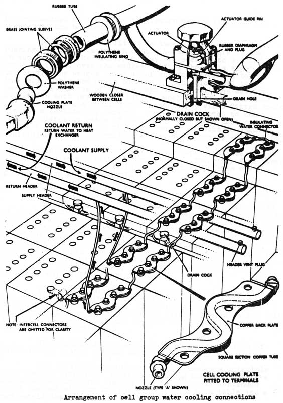
B. Components in Battery
Header pipes are the main carriers of cooling water in battery compartment which take the water from pressure side of the pump to the suction side of the pump.
Cell cooling plates (copper) are fitted to each side of the cells and are secured by the four terminal bolts
situated there. The heat is conducted from the cell to the terminals and the cooling plate, which has a tube fixed on its under side, is shaped to fit between adjacent terminal posts. It has the cooling water passing through the tube. This manner effects the best method of cooling each cell. (heat transfer)
The cooling plates are linked together and with the supply and return header pipes by lengths of rubber hose. They have a washer and jointing sleeve fitted at each connection. An insulating ring is also fitted over the hose to prevent surface leakage current which might result from condensation on the hose. The hose completes the water circuit from the pressure header through approximately nine cooling plates
11-17
Fig. 11.06
11-18
interconnected in series to the return header for each sub circuit in the batteries.
Drain cocks are fitted in two fore and aft rows
running the complete length of the battery. There is one
on each side of the battery. They are secured to a board
which is fitted over the wedges holding the cells tightly
together. The wedges being about one foot from the top of
the cell enable the drain cock to be set below cell top
level. The purpose of these cocks is to drain the battery
cooling in each particular battery when needed. A secondary
use is to vent the cooling system where the vents fitted couldn't
get out a certain air pocket. They are connected to the
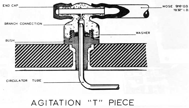
cooling plates by means of two rubber "T" piece hose connections
fitted to both sides of the interconnected cells to enable
draining both paths through the same drain cocks. (Fig. 11.06)
Vents are fitted to the header pipes and extended to the space above the battery compartment. There are five vents in the Control Room for #2 Battery and six vents in the Accommodation space for #1 Battery.
C. Components in A.M.S.
The gravity tank, or header tank, which is installed at the highest point of the system, is used to take up changes in volume of water in the rubber hoses due to pressure variations. When the system is started up, the hydraulic pressure causes the hoses to swell and water flows out of the tank. On shutting down the hoses contract and water is returned to the tank. The water in the tank, which enters the cooling system on the suction side of the pump, also will flow into the system when water is lost due to venting, leaks, etc. The gravity tank is filled from the main distilled water line.
Four water purifier tubes are connected in parallel to the cooling return line. These keep the level of purity and conductivity to safe limits. As there may be a potential difference between adjacent cooling plates as high as 100 volts, the water in the system must be pure and therefore a non conductor of electricity.
The purifiers have about 0.5% of the total flow of water in the system passing through them.
The purifiers operate on the ion exchange principle with the bed within the purifier removing both the positive and negative ions from the water. This process continues until the output from the purifiers is not acceptable and a new set is inserted.
11-19
In SS73 & 74 only one pump is fitted. The #2 pump has been removed.
11-20
There are two proportioning cocks; one of which is used to ensure the same amount of water flows through the system for each battery and the other to determine the amount of water in the return line will flow to the heat exchangers and return directly to the suction side of the pump.
There are three salinometer cells fitted.
(a) Local cell and salinometer measures the conductivity of the water leaving the purifiers. They are fitted fwd in the A.M.S. The scale of the meter on the salinometer is 0-5 units. When the conductivity of the water reaches 4 units the alarm light comes on and the meter falls back to zero. This protects the meter movement and the alarm light indicates the reading is greater than 4 units.
(b) The second cell in the A.M.S. measures the conductivity of the water leaving the pump or the water actually flowing in the system. The salinometer for this cell is in the main passage way in the Control Room.
(c) The third cell in the A.M.S. measures the
conductivity of the water in the main distilled water line. This is used to check the water before topping up the gravity tank. The salinometer for this cell is the one used for the cell which checks the conductivity of the water flowing through the system.
The remote reading salinometer (scale 0-50 units) for the two cells has a changeover switch so each cell may be connected to the meter individually. This is to enable checking of each part of the system separately. This meter, when its reading reaches 20 units, is so connected to the battery cooling pump motor starter, that the motor will stop and an alarm light comes on. When the meter reaches 40 units the meter will fall back to zero and the alarm light will remain lighted.
located in #4 M.B.T. port and starboard is a heat exchanger for the battery cooling water. With the submarine going through the water, sea water flows through the tubes of the cooler and cools the battery cooling water circulating through it.
When the submarine is alongside no sea water is flowing through the heat exchangers. However this is overcome by:-
In SS73 & 74 sea water from the overboard discharge of the after services system is put to the heat exchangers by opening the proper valve under the after casing.
In SS72 sea water is pumped by the ballast pump through the battery cooling main line valves and hull valves.
11-21
In SS73 & 74 Arctic Flaps are fitted to both heat exchangers which shut off the flow of sea water to the heat exchangers. These would be employed in cold waters.
There is one battery cooling pump fitted with a
28 p.s.i. relief to limit the pressure in the system in SS73 & 74.
In SS72 as in Fig. 11.07 there are two battery cooling pumps fitted with a 28 p.s.i. relief fitted to limit the
pressure in the system. One pump only is needed to keep the proper amount of water flowing in the system. The other pump is used as a standby. In normal practice the pumps are run up alternately to give equal running time to each.
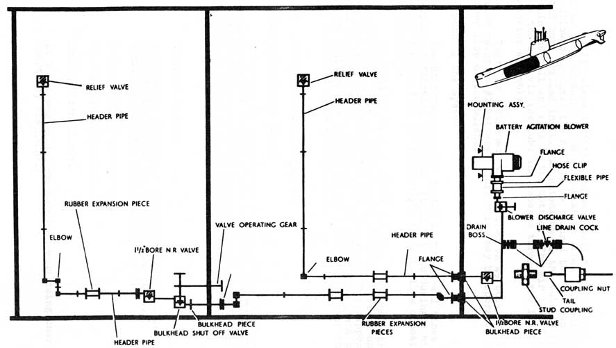
11.08 BATTERY AGITATION
The battery agitation system is one of low pressure air (1 1/2 p.s.i.) which is fed to each cell in the submariners main batteries. This air goes to the bottom of each cell through a tube fitted inside each cell and comes out in the form of
small bubbles. These bubbles rise and tend to get the electrolyte within the cell moving. This rising motion of the electrolyte keeps it all mixed within the cell.
The system is used to prevent stratification (prevent different density layers forming inside cell).
It also prevents high temperatures in local spots within cells and reduces all charging times by one hour.
A. Components in A.M.S.
Motor driven rotary blower which has filters over air intakes and a drain fitted on its discharge side to check for condensation or electrolyte before starting blower and air flow after blower is started.
There is a discharge valve fitted to the blower and after the line splits to go to #1 and #2 batteries there is a non return valve on the line to #2 battery.
B. Components in Battery Compartments
Header pipes carry the air within the battery compartments. These are fitted with e relief valve at the end which is normally shut. It will open when the pressure in the battery compartment becomes greater than that inside the header pipe thus preventing he electrolyte from coming up the tube within the cell and
blocking the 'T' piece.
Air is led to the cells from the header pipes by soft rubber tubing. This connects to a cell and each cell there after in series until the last in line fore and aft has a bung inserted to prevent the air escaping.
11-22
MAIN BATTERY ELECTROLYTE AGITATION SYSTEM Fig. 11.08
11-23
A 'T' piece is fitted to each cell to allow most of the air to pass through to the cell next in line. A small portion is allowed to enter the cell it is secured to, by means of a small hole drilled in it. An extension of the tube is fitted within the cell and runs to the bottom. The air then flows into the cell via the tube and escapes through the float indicator assembly.
There is a bulkhead valve fitted on 49 bulkhead in the system going to #1 Battery. This valve may be operated on either side of the bulkhead.
C. Running the System
The Battery agitation system is run at all times whilst charging or floating the load. It is not run during a high current discharge as the electrolyte tends to flow opposite to the agitation.
It shall be running whilst breaking a vacuum within the submarine. This is to ensure no electrolyte rises up the tube in a cell and reaches the 'T' piece. If this happens it could go into the line and damage the rubber tubing and short out the cells or one crystal of dried electrolyte over the hole in the 'T' piece will block it.
11.09 BATTERY ROUTINE MAINTENANCE
A. Battery headings (Dips)
A density and temperature reading of the pilot cell (a cell chosen for ease of access in each battery which is used to give an indication of the temperature and density of the battery as a whole) is taken and entered on the "Battery State Board" in the Control Room and in the Battery Log in the Motor Room.
A Dip is taken:-
Twice daily in harbour (usually before 0800 and at 2000 or when rounds are carried out. Battery ventilation is run up at the same time.)
Before putting on a charge.
Before Harbour Stations.
Once a watch at sea.
At the times laid down during an equalizing charge & quarterly discharge.
11-24
B. All Round Readings:-
Once a month and within 12 to 24 hours upon completing an equalizing charge the temperature and density of every cell in each battery must be taken. This is carried out to check each cell to ensure all cells are approximately reading the same and any which are low will have the proper action taken to find the reason.
C. Topping up:-
The normal discharge of gasses from a cell is hydrogen and oxygen. These gasses will be given off at all times and at a greater rate whilst gassing. They result from chemical reactions in the cell which causes the breakdown chemically of water (H2O) in the electrolyte.
After using the battery for a length of time the level of the electrolyte (indicated by the indicator float) will be found to be low and the battery will need topping up.
Topping up is carried out between 12 and 24 hours
after a charge. The reason for this is the level of electrolyte rises during a charge and whilst gassing it is at its largest volume. Between 12 and 24 hours after the charge the electrolyte is at its stable level and topping up then will ensure the cells are topped up the proper amount.
The usual way for this is to carry out an equalizing charge, carry out all round readings and then top up. An operational charge may be carried out upon completion of topping up to mix the electrolyte or battery agitation should be switched on for a few hours to mix the water with the electrolyte.
The water for topping up comes from the Distilled Water System to four topping up nozzles in each battery so placed as to give one nozzle with its hose for each corner of the battery. The water must be tested with silver nitrate before topping up is started.
D. Earth Leakage Test:-
Commonly called milliamp leak test carried out once a week on each battery. This is to ensure each battery is clear of earths and if one is found it can be traced to the cell and cleared.
E. Connection Tightness Check:-
Commonly called a torque test. The inter cell connecting straps have the terminal bolts securing them checked with a torque wrench set to slip between 95 to 100 lb/ft. This check is carried out once every six months to ensure no terminal bolts have worked loose which could cause a hot connection in the battery.
11-25
F. Milli Volt Drop Test:-
Carried out to test continuity resistance between terminal post and interconnecting strap.
It is done when battery is first put into submarine or has been disturbed. At least 1000 amps must be discharged and the tolerance is 1 millivolt per 100 amps flowing through each strap.
G. Periodic Wiping Down:-
This is done to remove any dirt, spilled electrolyte or water and corrosion from the cell tops and connecting straps. A clean battery is a trouble free battery.
11.10 SAFETY PRECAUTIONS TO BE TAKEN DURING BATTERY MAINTENANCE IN COMPARTMENT
No smoking in compartment or in compartment above battery.
Wear clothing which will cover body & limbs (sleeves rolled down)
No metallic objects to be worn or carried in pockets.
Tools used on battery are all insulated.
Battery off load.
Battery ventilation running.
Rubber mats should be used if work is ever carried out and a person has to lay on top of cells.
11.11 SICK CELL
A sick cell is one in which the voltage, density or
capacity is below the average of the remainder of cells in a battery.
A. A Sick Cell may be caused by:
Cell not topped up and tops of plates go dry.
Too much water put in during topping up and electrolyte spills over.
Separators break down and plates short out.
Crack in container and electrolyte spills into bilge.
Agitation system fails - blocked 'T' piece.
11-26
Impurities in electrolyte.
Sulphation - excessive lead sulphate crystals forming on plates.
A sick cell is usually found during All Round Readings and one whose density is 20 points below the average of the battery may be classed as a sick cell and must be checked to find reason for low reading.
B. Cutting; out Device:-
This equipment is used to cut out defective (sick) cells in each battery. The batteries are normally connected in parallel therefore equal numbers of cells must be cut out in each battery to maintain equal levels between the batteries. Four sets are carried onboard.
C. Cell Lifting Gear:-
Sick cells are removed from batteries (after wedging
has been removed and cells disconnected) by cell lifting
gear. This consists of a lifting top and leg irons. These
being secured to cell enables it to be lifted fro or lowered
into the submarine. Each submarine carries its own lifting gear.
11.12 Main Battery Log:-
This log is one in which all pertinent information concerning the battery on board is entered. It is commenced hen battery is first wetted down and is finished when battery is scrapped.
With this log the battery performance may be assessed at any time.
The log contains the following sheets:-
Dates of normal charges
Dates of equalizing charges
Dates of topping up
Dates of earth leakage tests
Dates of Tightness checks
Dates of All Round readings
Record of Sick Cells
Record of Battery Maintenance
Pilot Cell readings
Particulars of battery and history sheet
Signature sheet
Daily Cooling Water Salinity Readings
11.13 BATTERY FIRE:-
A fire in a main battery is an all hands evolution. A resultant explosion could cause serious damage to the submarine.
11-27
Action to be taken in the event of a battery fire:-
If charging - break the charge
Shut down battery ventilation - oxygen starvation
Take battery off load - open main and auxiliary power breakers. Open mid point link switch if able.
Shut ventilation flaps and stop agitation blower
Stop ships ventilation fans
Shut down bulkheads on either side of battery compartment affected
If cooling is running leave it running. This will help cool the battery compartment.
Consider cooling deck above battery and boundary bulkheads with distilled water.
Wait until bulkheads of battery compartment are cool at least 1/2 hour
One man (electrician) in a chemox is put into compartment above battery and hatch shut after him.
He will then feel deck above battery and if it is cool slowly open a battery hatch.
If fire is out the compartment may be opened up and ventilated.
Work may then be carried out to check and clean up damage.
Fire in a battery compartment would involve the same procedures as would a fire anywhere in the boat would involve. The charge shall be broken and both ventilation systems shut down.
The voltage range of the main batteries is 390 to 650 volts. These high voltages require constant caution and
qualified personnel only are to carry out work on equipment associated with the main battery.
11-28
PART II
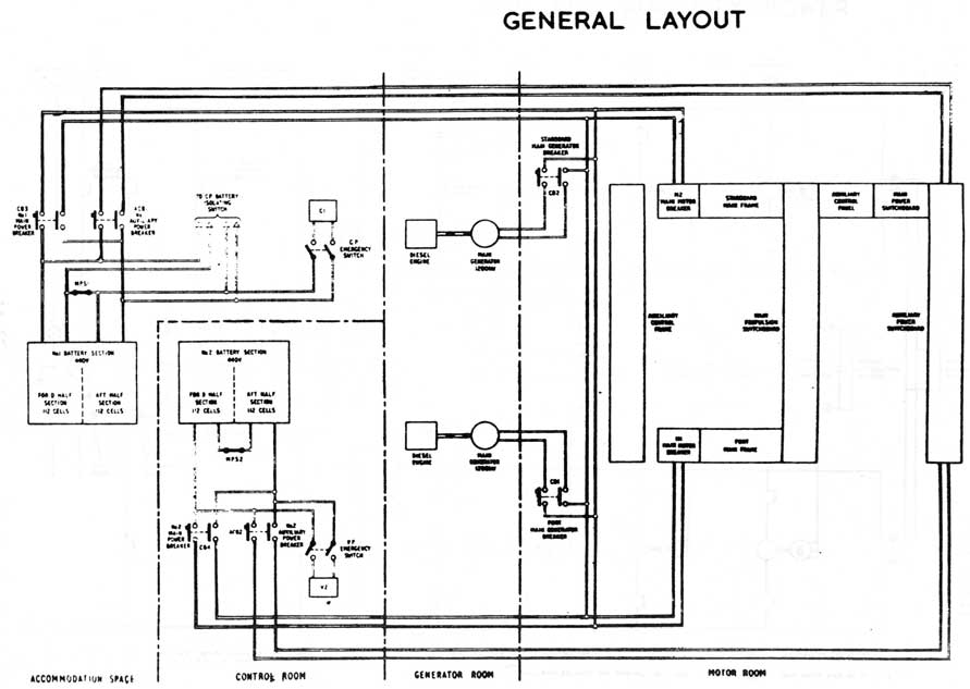
MAIN POWER SYSTEM
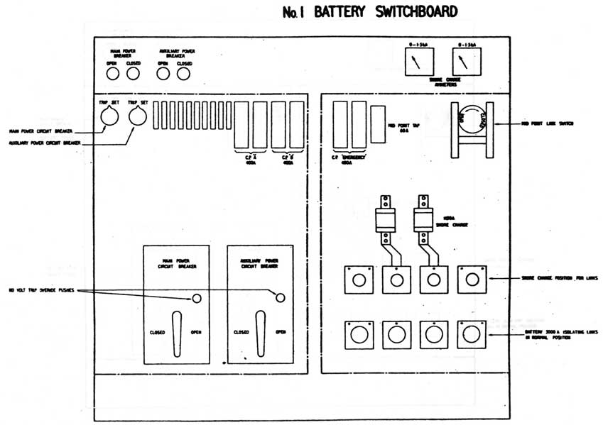
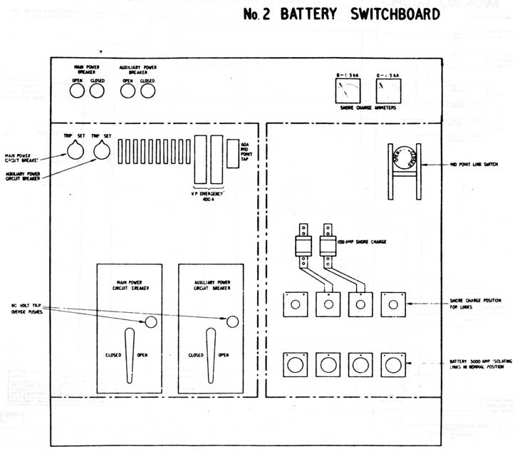
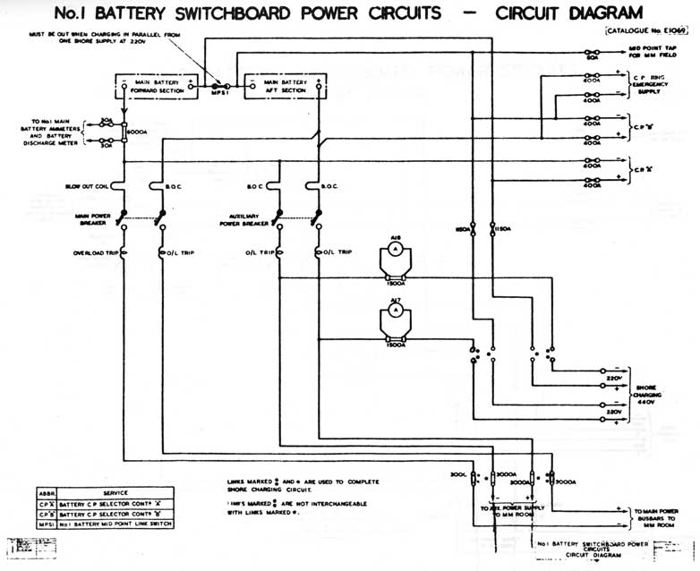
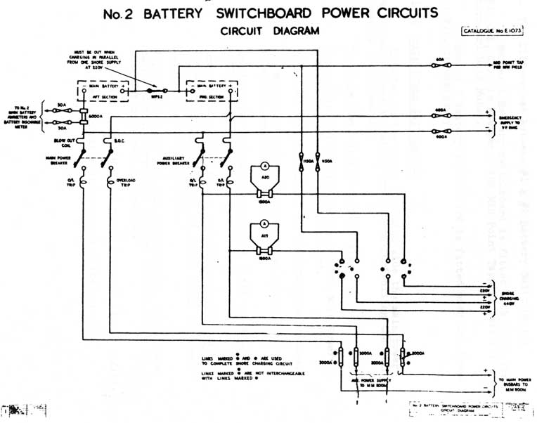
11.14 BATTERY SWITCHBOARDS
The battery switchboards are used to contain breakers and various other associated equipment to connect or disconnect the main batteries with the main and auxiliary Power buss systems.
Each battery has a switchboard. Number 1 Battery switch-board is located on the stbd side of the accommodation space and number 2 Battery switchboard is on the port forward side of the Control Room.
The cables leave the breakers and travel to the motor room on the side which the switchboard is located. They are protected by a shield which covers all the cables. Where the cables pass through the Control Room/Engine Room bulkhead, port and stbd, and the Control Room/Accommodation space bulkhead stbd side only; expansion boxes are fitted which allow for expansion and contraction.
A. The Battery Switchboards Contain:-
Main Power Breaker which connects the main battery to Main Propulsion Buss Bars. It is through the Main Power Breakers both main batteries are paralleled so they will discharge equally and densities fall equally.
Auxiliary Power Breaker which connects the battery to Auxiliary Power Buss Bars.
Mid Point Link switch which electrically splits the battery into two sections of 112 cells giving a nominal voltage of 220 volts.
Local "Set" "Trip" switches for each breaker. The breakers are also controlled remotely from the Motor Room and may be set by hand locally. When set by hand they must be tripped by hand.
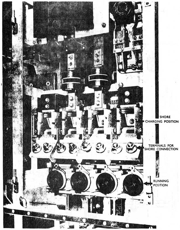
Shore charging connections when charging from a generator ashore or a submarine alongside.
Battery Isolating Links which connect battery to the shore charging position or Main & Auxiliary Buss Bars. These links "one starred" and "two starred" are not interchangeable.
Shore charging ammeters to indicate the amount the battery is being charged from ashore.
11-29
Fig. 11.09
11-30
Fig 11.10
11-31
Fig 11.11
11-32
Fig 11.12
11-33
Fuses for the ammeters indicator lights, breaker control circuits and etc. are also fitted.
B. The Differences Between #1 & #2 Battery Switchboards
Number 1 Battery switchboard is fitted with fuses for CPA, CPB, C.P. in Emergency and Mid Point Tapping fuse for the Starboard Main Motor.
Number 2 Battery switchboard is fitted with the fuses for V.P. in emergency.
11.15 MAIN POWER SWITCHBOARD
Situated in the Motor Room stbd side the main power switchboard gives a central location of controlling the Main Power in the submarine.
The Main Power Switchboard contains:-
The remote 'set' 'trip' switch for the Main Power Breaker in each battery switchboard.
The 'set' 'trip' switches for both Main Generators.
The Voltmeter selector switch which must be set to select on coming generator.
Ammeters for each main generators field and armature current.
Ammeters - two for each main battery which show the charge/discharge rate of the main batteries. One ammeter favours the discharge scale while the other favours the charging scale.
Voltmeters - one for each main battery, one for the main Propulsion Buss Bar voltage and one which is used for both main generators.
An engine speed (R.P.M.) meter for each diesel engine.
A diesel generator order receiver (telegraph).
11-34
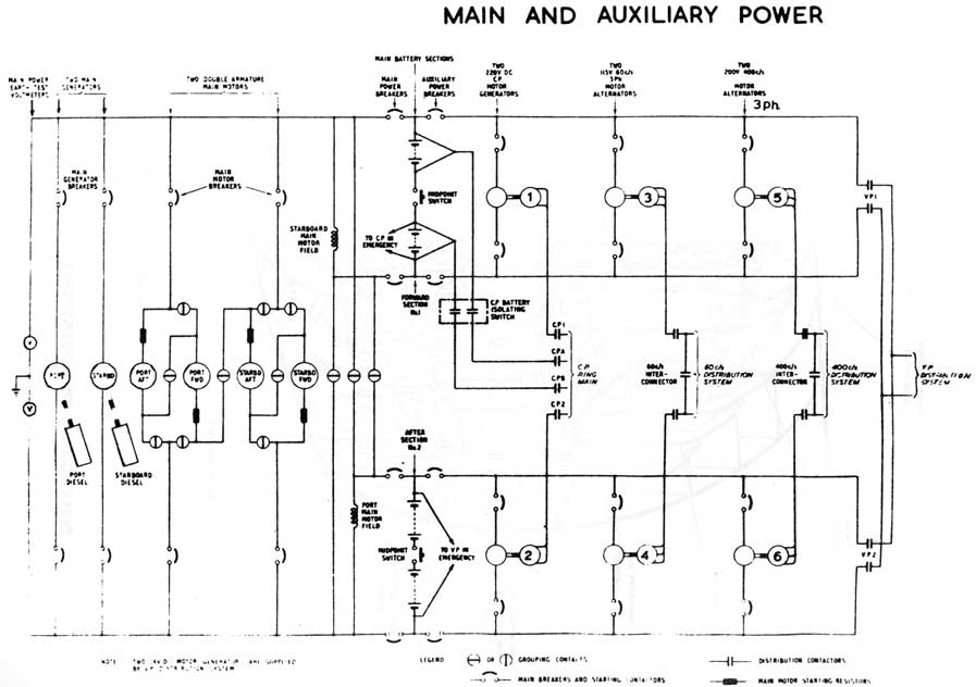
PART III
MAIN PROPULSION
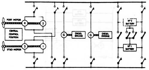
The propulsion in 'O' Class submarines is of the diesel-electric type. This system has the following advantages over the direct drive system:-
(i) Alignment between diesel engine and the propellor is not required therefore the generating plant may be situated anywhere and the whole generating plant (diesel engine and generator) may be resiliently mounted.
(ii) Engine speed is not dependant upon shaft speed and may be run at its best speed for the load.
(iii) No engine clutches fitted making battery propulsion faster and simpler.
(iv) Control of shaft speed is entirely electrical which makes it faster and simpler.
The power from the main batteries being supplied by the Main Power Breakers goes to the Main Propulsion Buss Bars.
The voltage being applied will vary from 390 to 880 volts due to the state of charge of the main batteries and electrical hookup of same.
The Main Propulsion buss is connected to the main batteries, main motors and main generators by their respective breakers. The arrangement is that all are connected in parallel to the Main Propulsion Buss Bars.
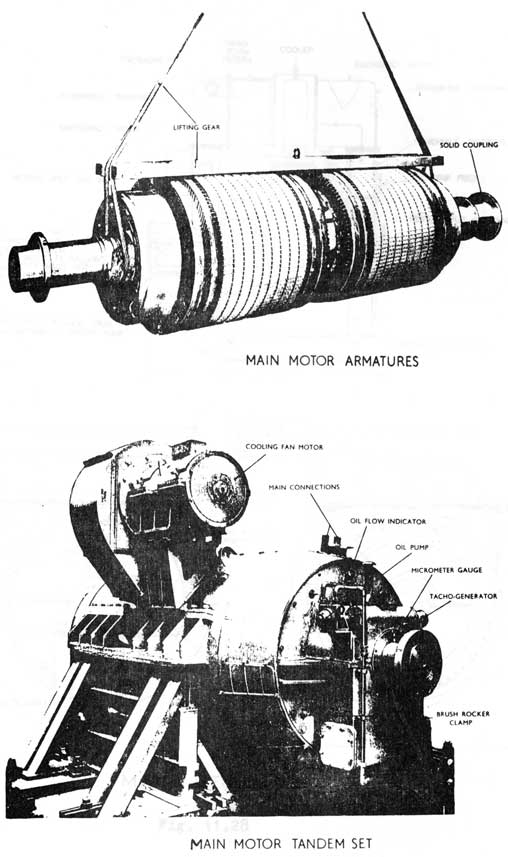
11.16 MAIN MOTORS
Two 3000 B.H.P. motors are fitted, connected directly to the ships shaft. The rotor of the motors has two armatures wound back to back on the same shaft and each armature has its separate shunt field. The power going to the armature circuit flows from the main propulsion buss to each main motors'
breaker and starting switches.
The bearings at each end are lubricated by a mechanically driven pump from a gear on the shaft.
This lubricating oil is in a 12 gallon sump and the pump lifts it up and discharges it over the bearing. The oil then falls back to the sump where it is cooled by a coil supplied with water from the After Services System.
11-35
Temperatures of the main bearings, air inlet and outlets are monitored on the Aux. Power Panel in the Motor Room.
The bearing temperatures of both main motors are recorded every hour.
The main motors are watertight up to the bottom of shaft level and splash proof above.
The main motors are fitted with heaters which are switched off prior to starting and on when motors are stopped. They are controlled by switches on the Aux. Power Swbd.
Each motor has a gear driven, from the shaft, tacho generator, which indicates the motor RPM on the main switchboard, OOW Panel & OMC.
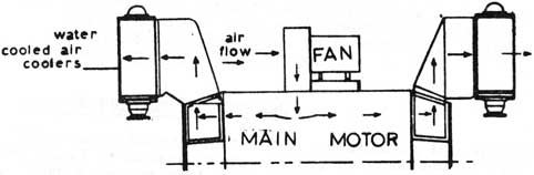
11.17 MAIN MOTOR BLOWER FAN
Each motor is fitted with a blower fan which cools the motor. This fan is mounted near the top on the outboard side of each main motor.
The fan cools the main motor by drawing air from the motor room into the main motor and it then goes out through the air coolers at each end of the main motor room. These coolers are supplied by the after services. This cools the ambient temperature of the motor room which is taken in to cool the main motors.
The air is forced from the motors through the heat exchangers in case of a leak in the cooler, water will not be drawn into the main motor.
Fig. 11.13
11.18 MAIN MOTOR CONTROLS
The speed of the main motors is regulated by the Grouper Handwheel and the Field Regulator.
11-36
A. The Grouper Handwheel:-
This handwheel through rod gearing controls a series of contacts. These contacts electrically connect the main motor to the main batteries giving different ranges of speed.
B. The Field Regulator:-
This will vary the speed of the main motors within a certain speed range as set by the Grouper.
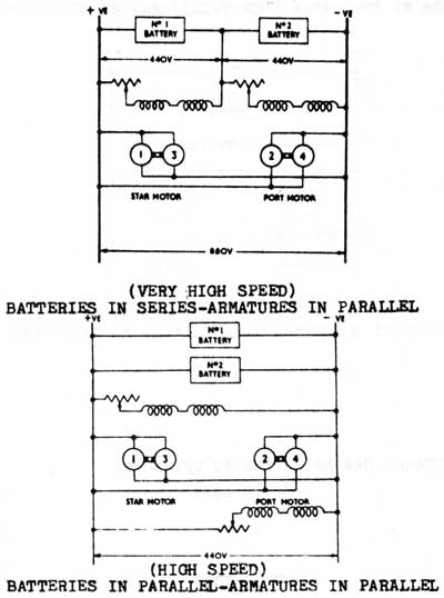
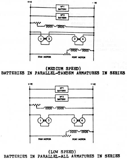
11.19 MAIN MOTOR GROUPING
The grouper has five positions or groups to connect the main batteries and motors electrically. Nominal Battery Voltage is 440 volts.
1. OFF - Armature volts zero
2. SHAFTS IN SERIES - Both main batteries in parallel giving 440 volts across all four armatures series or 110 volts per armature. This is the lowest
speed range.
3. GROUP DOWN - Both main batteries and motors in parallel with 440 volts across motors, whose armatures are in series giving 220 volts per armature. This is the medium speed range.
4. GROUP UP - Both main batteries and motors with each armature in parallel giving 440 volts across each armature. This is the fast speed range.
5. BATTERIES IN SERIES - With batteries in series and main motors with each armature in parallel giving 880 volts across each armature. This is the very high speed range.
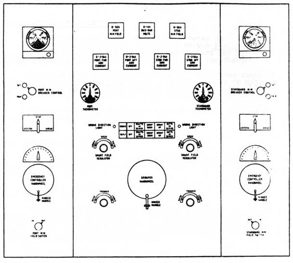
11.20 MAIN PROPULSION SWITCHBOARD
This switchboard is used for controlling the speed of the submarine ahead or astern only. It may be regarded as two
halves. Port side for port main motor and stbd side for
stbd main motor. The contents of one side of the switchboard are:-
A. Grouper Handwheel - controlling group of main motors and
batteries. Has its telegraph and reply with control fitted above it.
11-37
ELECTRICAL PROPULSION SYSTEM
Fig. 11.14
Fig. 11.15
11-38
FIG. 11.15
11-39
B. Field Regulators - used to vary current through main motor field which varies the speed.
C. Field Trimmers - used in Group Up or batteries in series
when the armatures of the motors are connected
in parallel to ensure equal current is
flowing through each armature circuit of
each motor.
D. Telegraphs and Replies - these are connected with the O.O.W. panel in the Control Room. The replies being located (Gongs) in the tower.
E. Trigger Switches - this switch has three positions, "Ahead", "Stop" and "Astern". When the trigger switch is moved to either position the field current of the motor must be full (35 amps.). Upon moving trigger switch contacts in behind control the camshaft motor which operates and turning a camshaft, in either direction, operate the starting switches in their proper sequence.
F. Emergency Handwheels - this is for use if the Camshaft Motor fails. Turning this handwheel turns the starting switches camshaft. It is fitted with an indicator to show position of camshaft i.e. How far in or out the camshaft is.
G. Field Switches - this switch supplies power to the main motor's shunt field which controls the speed of the motor by way of the Field Regulator.
H. Main Motor Breaker "Set" "Trip" switches - this switch controls the Main Motor Breaker.
J. Ammeters - one ammeter for each half of a motor connected in its armature circuit and one ammeter for the main motor field (6 ammeters in all).
K. Voltmeter - a voltmeter hooked across the main propulsion buss bars to give indication of applied voltage.
11.21 SINGLE ARMATURE RUNNING
If the Starboard main motor only becomes damaged in either the armature or circuit may be run on one armature. The damaged armature or field circuit is isolated from the operating motor armature and field circuits.
11-40
MAIN PROPULSION SWITCHBOARD LAYOUT
Fig. 11.16
11-41
To carry out this operation, various Change Over Switches must be operated and links must be removed. When in use the good half of the motor gets its field supply from the Mid Point Topping Fuse in #1 Battery Switchboard.
Single armature running is only carried out in the Group Up position i.e. when both armatures are connected in parallel.
11.22 AUXILIARY PROPULSION
If the Main Propulsion Switchboard becomes damaged and main motors are needed Auxiliary Propulsion on the Port Fwd Main Motor Armature may be carried out. The switchboard may be isolated from batteries to enable work to commence on the damage.
The Auxiliary Propulsion Panel in the motor room controls the port fwd armature by power which is supplied by #2 CP M/G. Ships supply for CP is then #1 CP M/G. Maximum revolutions are 120.
Various links and changeover switches must be changed to enable carrying out this operation.
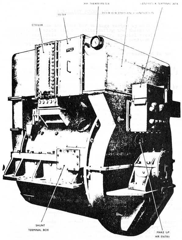
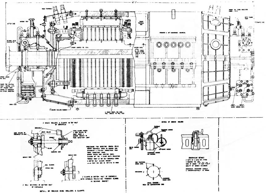
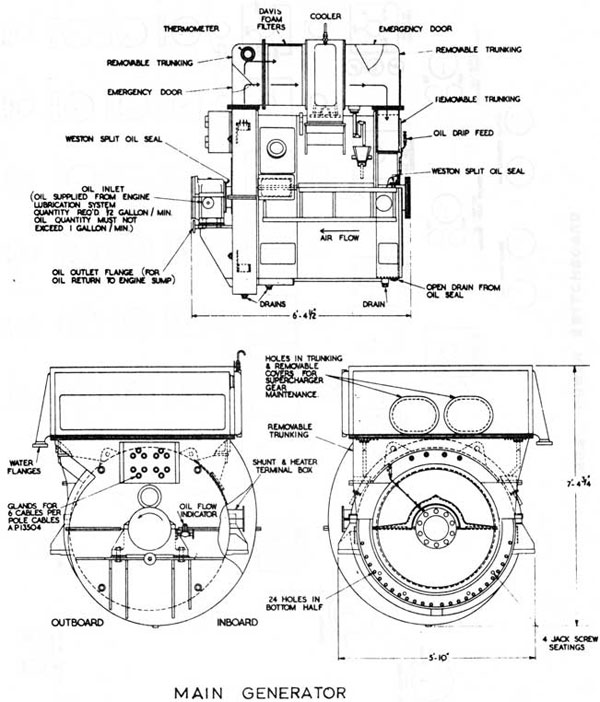
11.23 MAIN GENERATORS
To supply current for charging the main batteries or propelling the submarine diesel-electrically, two 1280 K.W. generators arc fitted.
The Main Generators are directly connected to the Main Diesel Engines (ASR1 16VMS) in the Engine Room.
The Generator outputs are connected to the Main Propulsion Buss Bars by breakers. These breakers are the only ones fitted with reverse trips for the protection of the generator. The breakers are operated electrically from the Power Switchboard and locally by hand.
The Generators are cooled by means of an impeller mounted on the shaft which circulates air through a filter (consisting of 16 plastic foam filters in each generator) and a water cooler which is supplied by the after services. The same air is circulated within the machine and make up air enters through a wire gauze covered opening below the terminal box.
The Generator has one bearing (pedestal bearing) which is lubricated from its diesel engine lube oil supply rail.
Each Main Generator has heaters fitted to keep the machine dry. These are switched on when machine is stopped and off just prior to being run up to be put on load. The switches for the control of the heaters are located on the Aux. Power Swbd.
11-42
MAIN GENERATOR
Fig. 11.17
11-43
PART IV
AUXILIARY POWER AND ELECTRICS
Because the Buss Bar voltage varies approximately between 390 volts and 650 volts during the charging and discharging cycle of the main battery, special provisions must be made for generating the direct current, constant voltage and alternating current.
The Auxiliary Power Buss is to be considered in two sections.
One section which is supplied from #1 Battery by its Aux. Power Breaker will feed power to the motors of nos. 1, 3 & 5 M/G sets and VP1 contactor.
A second section which is supplied from #2 Battery by its Aux. Power Breaker will feed power to the motors of nos. 2, 4. & 6 M/G sets and VP2 contactor.
This means both supplies from the main batteries are not paralleled through the Aux. Power Buss Bars. If damage occurs in a battery compartment the M/G sets running off that battery may be shut down and the corresponding M/G set fed from the other battery may be run up. This will affect no loss in any power system due to a battery fire, flood or any other circumstance.
The Auxiliary Power System is divided into five separate electrical systems which are:-
(i) Variable Pressure (V.P.) Ring Main System
(ii) Constant Pressure (C.P.) Ring Main System
(iii) 205V 400 C/S System
(iv) 115 V 60 C/S System
(v) 24.V DC System
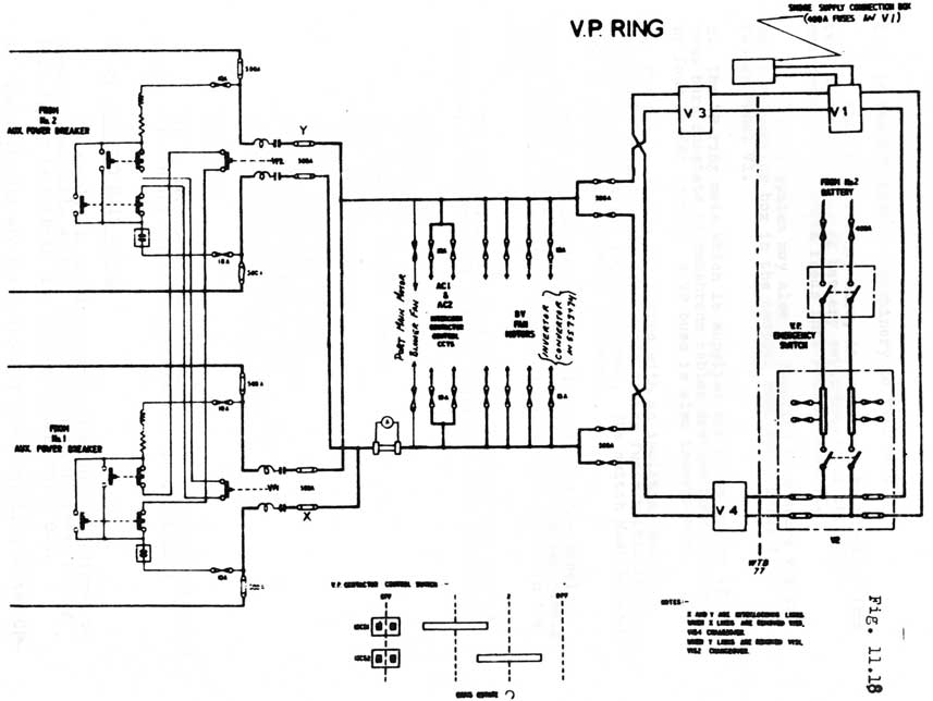
11.24. V.P. MAIN SYSTEM
Designed to supply power to machinery and equipment designed to operate in a voltage range of 390 to 650 volts. The voltage of the system is dependant upon the voltage of the battery from whence it is supplied.
A. The VP system is normally supplied from #1 and #2 battery sections via the auxiliary power breaker and auxiliary power buss bars and a pair of double pole contactors (VP1 & VP2) which are interlocked to prevent both being made together. This is done to prevent paralleling both main batteries through the small contactors which could cause serious damage if the batteries were out of step. However the changeover
11-44
V.P. Ring
Fig 11.18
11-45
time is insufficient for machinery to fall off.
The VP system may also, in emergency, be supplied from two fuses located in #2 battery switchboard via the VP in emergency switch which feeds into Feeder Panel V2.
The VP system may also be supplied from shore via the shore connection box in the control room which feeds into Feeder Panel V1.
B. The VP ring main which is supplied via fuses on the VP buss bars consists of neoprene cables divided into sections by four feeder panels. A VP buss is also incorporated.
C. The Feeder Panels are fitted with an isolating switch
which when opened kills the supply to the fuses within it for various equipment fed from the panel. The switch must be opened before opening the doors on the panel.
There are isolating links fitted inside the panel
which enable sections of the cable run and other feeder panels to be isolated in event of damage at the proper places in the ring.
The following is a list of equipment fed from the VP Ring Main System and a VP failure would make them inoperable.
Ballast Pump
Trim Pump
After Services Pumps
Low Power Motor/Generators
L.P. Blower
H.P. Air Compressors
Hydraulic Pumps
Battery Ventilation Fans
A.C. Interconnect Contactors
Port Main Motor Blower Fan
Air Conditioning Plant Compressors
Inverter-Convertor (SS73 & 74)
CAUTION:
VP is very dangerous therefore only qualified personnel are to work on any affiliated equipment. IT CAN KILL !!
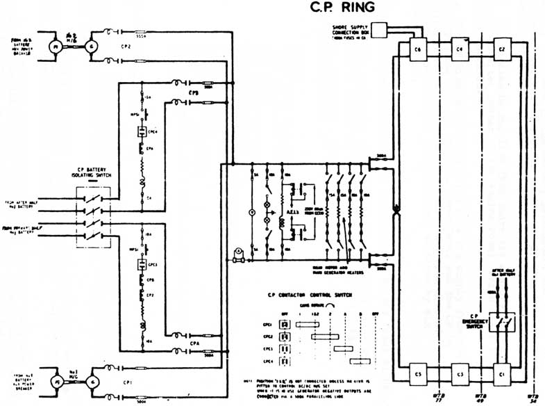
11.25 CP RING MAIN SYSTEM
To supply all machinery and equipment not designed to work on a variable voltage range the Constant Pressure Ring Main System is fitted. Its voltage is 220 Volts D.C.
A. The following are the sources of power supplied to the CP Ring Main System:-
11-46
(i) #1 100 KW M/G (CP1)
(ii) #2 100 KW M/G (CP2)
(iii) Forward half of #1 Battery (CPA)
(iv) After half of #1 Battery (CPB)
(v) After half of #1 Battery (CP in emergency)
(vi) Shore Supply
The four normal supplies to the CP system are selected by the CP selector switch on the Aux. Power Swbd.
B. The 100 KW Motor/Generators supply the CP Ring via their individual contactors (CP1 & CP2) from the generator.
The motor for each M/G set gets its power from the Aux. Power Buss Bars which are supplied from each battery by its Aux. Power Breaker.
The Motor/Generators are situated in the forward lower Motor Room and they have an air cooler supplied from the after services system.
The speed of the motor is kept constant by an Automatic Frequency Regulator (AFR) which is the Motor Room passageway.
The voltage output of the generator is kept constant under various loads by an Automatic Voltage Regulator (AVR) which is situated in the Motor Room passageway.
The generators may be paralleled during changeovers of machines so as to have no interruption of power supply. With one machine on load the oncoming machine is put on load (parallel operation) by closing its contactor. The CP selector is used in conjunction with the "set" buttons for CP1 & CP2 contactors.
The normal way of supplying the C.P. system is by either of the M/G sets.
C. CPA & CPB are considered an alternative means of supplying the CP System.
The source of CPA & CPB is the forward and after halves of #1 battery via fuses in the Battery switchboard and the CP isolating switch (situated in the Motor Room passage) and each respective CP contactor.
CPA and CPB contactors are controlled by the CP selector switch and do not (as each M/G set contactor does) have a contactor "set" button.
Number 1 Main Battery must be split electrically (mid point link switch open) before CP is supplied from either half of the battery thus giving a nominal voltage of 220 volts.
11-47
Fig 11.19
11-48
D. CP in emergency is supplied from the after half of #1 Battery via fuses in the Battery Switchboard and the CP in Emergency Switch. The power enters the CP Ring Main through Feeder Panel C1.
E. CP may also be supplied from shore via a shore connection box (port after corner of the engine room) which feeds into Feeder Panel C6.
F. The CP Ring Main System which gets its supply from the four CP contactors in the Aux. Power Swbd. and the CP in Emergency switch consists of a buss and a ring made of neophrene cables which is broken into sections by six Feeder Panels.
G. The Feeder Panels are fitted with an isolating switch which when opened isolates all equipment fed by the fuses within.
The panels are also fitted with isolating links which may be removed to isolate damage else where in the ring.
H. The following is a list of some equipment onboard fed from the CP system:-
Galley
Ships vent fans and Heaters
Main Motor and generator heaters
AEL Relay
CO2 Absorption Units
Oxygen Generators
Lube oil heaters and Separator
Fuel oil separator
D.O.T. Heaters
Battery cooling pump
Oily bilge pump
Combined fresh water & lube oil priming pump
Klaxon
11.26 AEL RELAY
The master AEL relay is fitted behind the Aux. Power Swbd and is normally supplied with 220 volts DC from the CP Buss. This in turn supplies the relays in each AEL throughout the boat.
With a CP failure the master relay de-energizes and its contacts change over to a supply of 230 volts 60 C/S which is then applied to each AEL throughout the boat.
When both the CP and the 60 C/S supplies fail, the
relays in the AEL's become de-energized and make a contact which puts its battery (a single wet cell inside) across the light of the lantern. As pointed out a failure of either the CP
(220 volts DC) or 60 C/S (230 volts AC) supply will not operate the AEL's (Automatic Electrical Lantern).
11-49
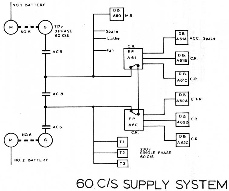
11.27 60 CYCLE SUPPLY SYSTEM
To supply all machinery and systems which operate on 115/230 volts 60 C/S two 15 KVA 60 C/S 3 PHASE Motor/Alternators are fitted.
A. The Supply System
Output from the alternators supply the 60 C/S system ring main via individual contactors AC5 and AC6.
Another contactor AC8 interconnects the port and starboard halves of the system to enable one machine to supply the entire system. This is needed as there is no paralleling equipment fitted and there is a break in power supply during changeover of machines.
B. Distribution
Each machine feeds one main Feeder Panel via its individual contactor. The system then branches into distribution boxes for various systems.
A Feeder Panel marking of A62 indicates
A6 - Alternating Current of 60 C/S system
2 - Box is fed from #6 machine.
C. Feeder Panels
If a VP failure occurs (which would result in
contactor AC8 becoming de-energized and half of the 60 C/S
system becoming dead) a three position "Normal" "OFF" & "Emergency"
switch may be operated on the dead Feeder Panel which will
then get its supply from the other Feeder Panel which is
alive. This also could be done if the contactor AC8 became
unserviceable or if the other Motor/Alternator set could
not be run up.
D. The motor speed is controlled by an Automatic Frequency Regulator (AFRO which will keep frequency output steady at 60 C/S.
The generator output voltage is controlled by an Automatic Voltage Regulator (AVR) which will keep voltage constant at 115 V in the system.
E. Some equipment and the supply to test sockets is 230 volts. This is achieved by three transformers in the motor room.
F. Some of the equipment using 115/230 volts 60 C/S are:
Fluorescent lighting & domestics
1 HP vent fan
Hydrogen clearance fans
Intercoms and Main Broadcast
AEL Relay
11-50
Fig 11.20
11-51
W/T Sets
Radar sets
Sonar sets
Lathe
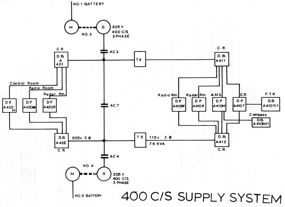
11.28 400 CYCLE SUPPLY SYSTEM
To supply all machinery and systems which operate on 205/115 volts 400 C/S two 15KVA 400 C/S 3 Phase Motor/Alternators are fitted.
A. The Supply System
Output from the alternators supply the 400 C/S system via individual contactors AC3 & AC4.
Another contactor AC7 interconnects the port and
starboard halves of the system to enable one machine to supply the entire system. This is needed as there is no paralleling equipment fitted and there is a break in power during changeover of machines.
B. Distribution
In SS72 the distribution system is the same as for the 60 C/S system.
In SS73 & 74 each machine feeds one main Distribution Box via its individual contactor. The system then branches into Distribution Panels for various systems.
C. Distribution Boxes (SS73 & 74)
These boxes, which are fed from the machine contactors are situated in the Control Room.
These boxes do not have a changeover switch and only supply power to various Distribution Panels.
The Distribution Panels have a three position "1", "OFF" and "2î switch which is changed over to the live position during a power failure. This means that every distribution panel
which is not in the live position, i.e. position "2", if
#4 M/A set is running, and the interconnect fails, will become dead and the Distribution panel C.O.S. will have to be switched from the "1" position to the "2" position.
A Distribution Box marking of
(i) A421 indicates
A42 - Alternating Current of 400 C/S system @ 205 volts 1 - Box is fed from #3 M/A set.
11-52
Fig 11.21
11-53
(ii) A411 indicates
A41 - alternating current of 400 C/S system @ 115 volts 1 - Box fed from #3 M/A set.
D. Feeder Panels (SS72)
These panels are connected and are similar to that of the 60 C/S system. This entails the same changeover for emergency supply as for the 60 cycle system.
E. Frequency & Voltage Regulations
The speed of the motor is controlled by an Automatic Frequency (AFR), which will keep frequency output steady at 400 C/S.
The voltage output of the alternator is kept constant and correct (205 volts) by an Automatic Voltage Regulator (AVR).
In order to supply equipment and systems which operate on a steady voltage of 24 volts DC the Lower Power system is fitted.
A. System Components
1. Two 4K.W. Motor/Generators are fitted and the normal situation is one machine running and the other used as standby.
2. One 24 volt battery is fitted of the lead acid type.
(i) In SS72 the Low Power battery consists of two 12 volt batteries in series. One cell however is cut out to give a nominal voltage of 24 volts. (11 x 2.2 = 24.2 v) Battery rating is 125 Ampere/Hours.
(ii) In SS73 & 74 the Low Power battery consists of four 6 volt batteries in series. One cell is cut out to give a nominal voltage of 24 volts. This battery has a much higher rating (350 Ampere/Hours) than that fitted in SS72.
11-54
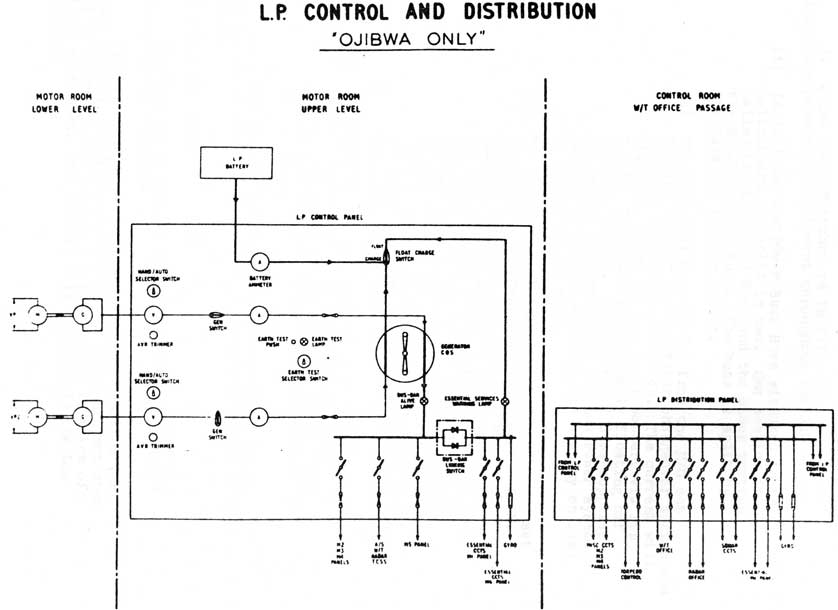
L.P. Control and Distribution
"Objiwa Only"
Fig. 11.22
11-55
3. A Low Power Switchboard is fitted to supply the various fuse panels and equipment throughout the submarine.
(i) In SS72 the Low Power Buss Bars situated in the switchboard are split in two. One section is called the Essential Buss and the other section the Non-Essential Buss. The buss is split by the Buss Bar Linking Switch.
(a) The Essential Buss is fed from the M/G set running through the generator changeover switch and the Buss Bar Isolating Switch. The current will also pass on to the Low Power battery via its C.O.S. The battery is normally floating off the running M/G. The Essential Buss supplies all essential services on the Low Power system. Failure of the M/G will put the battery on load to the Essential Buss.
(b) The Non-Essential Buss is fed from the M/G set running via the generator changeover switch. The non Essential Buss feed all non vital services of the Low Power System. Failure of the M/G will put the battery on load and the Essential Buss will be energized but as the current passes through the Buss Bar Linking Switch it operates a reverse current mechanism and the switch opens. This gives supply to the Essential Buss but the non Essential Buss will receive no supply.
(ii) In SS73 & 74 the Low Power Buss is not split in two and there is no essential or non essential buss. Failure of an M/G will put the battery across the buss and everything fed from the buss is supplied.
4. Each M/G set has a hand and automatic voltage regulator to adjust voltage output of the generator and keep it constant.
B. Battery Charging
The battery during its use will require occasional discharging and charging.
With the system in its normal running position (one M/G set on load, the battery floating and other M/G set shut down) to discharge the battery the running M/G is taken off load and shut down. The battery will then supply the Low Power Buss.
11-56
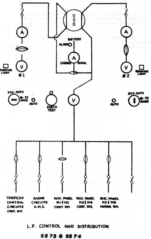
Fig. 11.23
11-57
When the density of the battery is lowered to its desired reading an M/G set is run up and put on load to supply the L.P. Buss and the battery switched from float to charge.
The other M/G set is run up and in "hand" put on load to charge the battery. The battery charging rate is adjusted by the hand voltage regulator until the charge is complete.
C. Voltage Regulation
Each M/G set is fitted with a Hand Voltage Regulator which adjusts the voltage output of the generator manually.
Each M/G set is also fitted with an Automatic Voltage Regulator (AVR) which automatically keeps voltage at Value set.
D. Equipment Supplied by the Low Power System
Essential
(Main Vent and Kingston Panel (O.M.C. (Overspeed trips on M/G's (6) (Gyro
Non Essential
(Indicating system (Sonar circuits (Radar circuits (Torpedo control (Telegraphs and replies (W/T circuits
11.30 FREQUENCY AND VOLTABE REGULATORS
The frequency and voltage regulators fitted to numbers 1, 2, 3, 4, 5 & 6 M/G sets are of the magnetic amplifier type.
The voltage regulators fitted to the Low Power M/G's are of the carbon pile type.
11-58
Fig 11.24
11-59
MAIN BATTERY SWITCHBOARD SHOWING LAYING OFF LINKS
Fig 11.25
11-60
Fig. 11.26
11-61
Fig. 11.27
11-62
Fig 11.28
11-63
Fig. 11.29
11-64
Fig. 11.30
11-65
Fig 11.31
11-66
Large Plate on Separate Page
Propulsion Control Equipment Fig 11.32
11-67
Large Plate on Separate Page
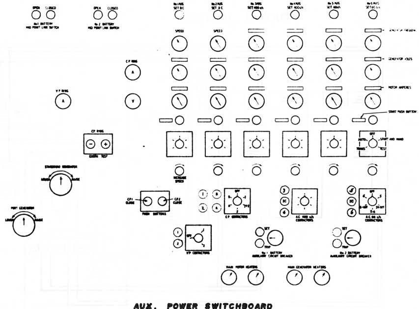
Auxiliary Control Equipment Fig 11.33