C.F. 'O' Class Submarines - Propellers and Shafting, describes the propellers, shaft seal and shafting of the Oberon class submarines.
In this online version of the manual we have attempted to keep the flavor of the original layout while taking advantage of the Web's universal accessibility. Different browsers and fonts will cause the text to move, but the text will remain roughly where it is in the original manual. In addition to errors we have attempted to preserve from the original, this text was captured by a combination of optical character recognition and human typist. Each method creates errors that are compounded while encoding for the Web. Please report any typos, or particularly annoying layout issues with the Mail Feedback Form for correction.
Propulsion fo the submarine is achieved by twin screws, driven through port and starboard shafting, directly coupled to two main propelling motors sited between frames 94-103, one on either side of the centre line of the ship.
Each motor has its own switchboard fed direct from either of two main battery sections, connected in parallel, and sited low down in the vessel immediately forward of the Control Room. Alternatively, each motor may be fed direct from one of two diesel-driven generator sets installed in the main Generator Room. The generator sets are provided primarily for charging the main batteries.
15.02 SHAFTING (SEE PLATE 1)
Each run of propeller shafting is arranged in three lengths, a thrust shaft, intermediate and a tail shaft coupled together by flanges and fitted bolts and nuts. The dimensions and weight of each shaft are as follows:
Shaft
Diameter (in.)
Length (ft. - in.)
Weight
Thrust
7.25
5-10
17 cwt.
Intermediate
7
2-11
6.5 cwt
Tail
7 (nominal)
32-9.25
2.6 ton.
The overall length of shafting is supported by:
a. A Michell type thrust block.
b. A stern tube bearing (through which the shafting extends from inboard to outboard).
15-2
Large Plate on Separate Page
Main Propulsion Machinery & Shafting Plate 1
15-3
c. An "A" bracket bearing, provided to take the weight of the propeller and to steady the shafting where it extends aft, outboard from the hull.
The shafting is arranged with a horizontal rake of 0.5918 in. per foot run, the centre line of each length being maintained at 11 ft. 9 in. below a horizontal plane through which the datum line may be assumed to pass. Thus, the distance between the two propellers is 11 ft. 6 in., whilst the distance between the forward ends of the main motor armature shafts is 6 ft.
To save weight each section of shafting is bored to form a hollow shaft, the ends of which are closed by screwed plugs locked with countersunk screws.
All couplings, tapers and keyways on the shafting are made, drilled and fitted to jigs and gauges. The mating faces of each coupling are marked to ensure correct assembly and the heads of all coupling bolts are drilled and tapped 3/4 in. BSF for the attachment of an extractor.
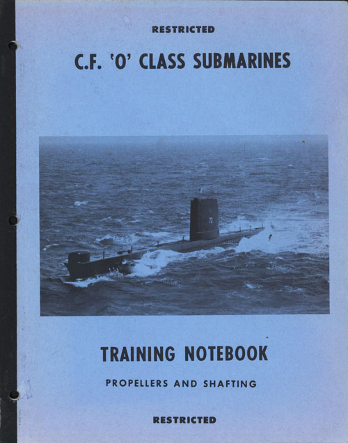
For shipment, or for the purpose of subsequent withdrawal, the inboard end of the tail shaft is provided with a loose coupling (Fig. 1).
15-4
Fig 1 LOOSE COUPLING
15-5
The tail shaft and its associated loose coupling are paired units, each coupling being keyed (three Sled keys) to the shaft and drilled to take eight 1.25 in. coupling bolts. This end of the shaft together with the coupling carries 3 wormwheel, the wheel forming part of the shaft turning gear. The outboard end of the shaft is tapered and machined to form a right hand thread to take a propeller nut.
Two keys, fitted diametrically opposite keyways in the shaft locate the propeller, whilst over that part of the shaft which passes through the 'A' bracket bush, a gunmetal bush is shrunk. The length of the shaft outboard, between the 'A' bracket and stern tube bearing bush, is wrapped in bandages impregnated with Araldite. To prevent ingress of sand to the stern tube bearing bush, a sand
excluder is provided. This consists of a split rubber sleeve clamped around the tail shaft and positioned so that its flanged forward end is just clear of the flange of the stern tube bush when the shaft is hard forward on the ahead thrust pads.
The intermediate shaft is arranged between the thrust shaft and the tail shaft. The forward coupling flange of the intermediate shaft is drilled to take eight 2 3/8 in. dia. coupling bolts. The after coupling flange of this shaft is counterbored to accommodate the loose coupling retaining ring which is made in halves and held in a groove of the tail shaft by binding wire. Between the forward coupling flange of the intermediate shaft and the after flange of the thrust shaft is bolted a drum forming part of a shaft brake assembly.
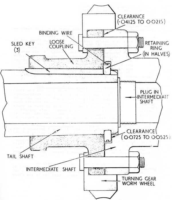
The thrust shaft, is provided with a thrust collar and a coupling flange at each end. The forward flange is secured to the propelling motor armature shaft coupling by nine 1 3/4 in. dia. coupling bolts and nuts. The after coupling flange is connected to the intermediate shaft by eight 2 3/8 in. dia. coupling bolts and nuts. The thrust shaft, where it extends forward from the shaft space into the motor room, passes through a conventional type bulkhead gland (Fig. 2).
So that the horse power transmitted by each line of shafting can be measured during tests or trials, a mounting for a torsionmeter is provided beneath each intermediate
shaft aft of the shaft brake.
15-6
Fig. 2. BULKHEAD GLAND
15-7
15.03 THRUST BLOCKS (See Plate 2)
Each thrust shaft is supported in a pair of horizontally split journal bearings both of which are whitemetal lined, housed within a Michell type thrust block sited in the shaft space.
The casing of the thrust block is split horizontally in a plane level with the centre line of the shaft, the two sections being bolted and dowelled together. The lower half of the casing is stiffened and is secured to Beatings by eight holding down bolts. Where the shafting extends through each end of the casing, a split oil seal is provided. This seal is retained in a split housing which is bolted to the casing by an end plate in halves bolted to the housing.
The propeller thrust is transmitted through the agency of two sets of thrust pads housed within the thrust block casing. Each set consists of eight pads held in contact with the bearing surfaces of the thrust collar, the forward set taking ahead thrust and the after set the astern thrust.
The thrust pads are supported within the block by half retaining rings located by webs within the block casing. An adjusting liner is placed behind each half retaining wing to maintain the axial position of the shaft. The retaining rings are held in position and prevented from turning by stops. Similar stops are employed to prevent the thrust pads from turning out of their recesses and half retaining rings.
Each thrust pad is faced with whitemetal and has a step formed on its back. The step allows the pad to rock slightly and establishes the formation of a wedge of oil between each pad and the thrust collar face when the shaft rotates. Axial movement of the thrust shaft is thus limited to the total clearance between its collar and the two sets of pads.
The interior of the thrust block casing contains two compartments, an inner containing the thrust collar, the thrust pads, the retaining rings and the adjusting liners and an outer which is common to the journal bearings, the outer surroundings cavities end the gland seals. The outer compartment functions as an oil reservoir and is closed at the lower end by a sump bolted to the bottom half of the thrust block casing.
The two compartments communicate with one another via four suction pipes which lead from the bottom of the inner compartment down into the sump as illustrated. Within the sump a strainer and a drain plug are provided. The top half of the block casing is provided with two inspection doors and a filling pipe fitted with a screwed cap. The pipe extends downwards through the outer compartment of the block into the sump.
provision is made for a dip rod, engraved to indicate the maximum and minimum permissible standing oil levels also an appropriate running level. At maximum standing oil level the bottom of the journal bearing surfaces are just covered with oil. The end of each bearing is lipped to ensure the retention of a sufficient quantity of oil in the bearing should the oil level fall dangerously low. The journal bearings are fed with oil from the inner compartment of the block by means of a viscosity pump incorporated in the thrust block cooling arrangement.
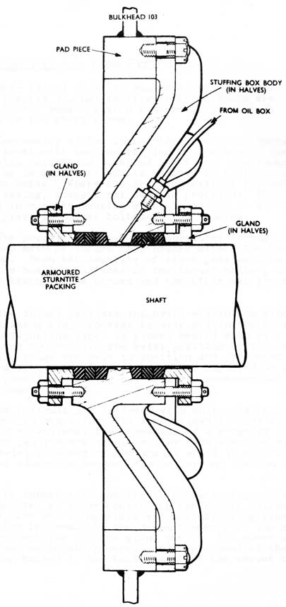
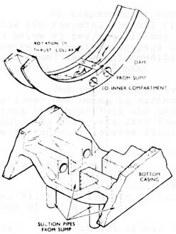
The pump (see also Fig 3) consists of a whitemetal lined ring in halves, dowelled and bolted together around the rim of the thrust collar. The rings runs in a groove machined on the inner surface of the upper and lower halves of the thrust block casing. When the shaft starts revolving the viscosity of the oil causes the thrust collar to carry the ring around with it until the movement of the ring is arrested by either one of two projections on the ring coming into contact with a dexine faced internal stop, mounted one on each of the inspection doors on the upper half casing. The arc of movement of the ring is about 110. When either of the stops holds the ring stationary one of two pairs of ports drilled through the bottom of the ring registers with one of two pairs of ports drilled in the bottom of the lower half of the casing. Each pair of casing ports communicate with an associated pair of suction pipes leading into the oil sump. The bottom part of the ring is shaped on the inside to form two oil wells and midway between these is fitted a whitemetal faced dam or baffle plate the face of which skims over a thrust collar. The dam also serves to interrupt communication between each pair of ports in the lower half of the block casing. in this manner the pump ports on the leading side of the dam, when the ring projections reach one of the stops, establishes communication directly into the inner compartment while the ports on the trailing side coincide with the ports leading to two of the four suction pipes. Most of the oil carried round by the thrust collar is scraped off by the dam and flows into the bottom of the inner compartment. On the trailing side of the dam the
15-10
VISCOSITY PUMP PORTS.
thrust collar tends to draw oil from the sump into the space between the thrust collar and the inside of the pump ring. As the action continues the whole of the inner compartment fills with oil while the level in the outer compartment falls approximately 3 1/2 to 4 in. Oil then starts to overflow from the top of the block through an outlet pipe to a sea water circulated cooler mounted adjacent to the thrust block. From the cooler the oil returns to the bottom of the thrust block sump. A restriction plug, fitted in the outlet pipe, maintains a slight oil pressure in the thrust block casing.
A sight glass is provided in the top half of the casing through which oil flowing from the block on its way to the cooler can be observed. Oil should be visible in the glass under all conditions of running, in the form of a thin jet from a nozzle fitted within the sight glass body, indicating that the casing is filled with oil and that the viscosity pump if working.
With the oil in the thrust block at its normal standing level, the oil flow, which is dependent on the temperature of the oil, should appear at approximately the undermentioned times after the shaft has commenced rotating.
Oil Temperature
Rev /min
Time (in secs.)
100 F.
400
30
230
50
140
85
30
435
145 F.
60
362
45
596
30
3028
15-11
At temperatures above 100°F and shaft revolutions below 100 rev/min. the oil flow will not be visible at first and below 45 rev/min. it may not be visible for some time. However the bottom two pads on each side of the thrust collar are drowned under all conditions and these will carry easily the thrust at 45 rev/min.
Two thermometers are fitted in the thrust block, the lower one being in contact with the oil only when the casing is almost full and under running conditions reads about 5 to 8 degrees less than the actual oil temperature. The thermometer pockets should be kept full of oil.
The cooler is circulated with sea water supplied from the after services.
The thrust block is designed to work satisfactorily when tilted 35 degrees in any direction and to withstand a shock of 225 g.
Note: The thrust blocks can be adapted for the fitting
of thrust meters so that the lead (in ton/sq in.) can be measured. This entails the fitting of special thrust meter rings and pads in lieu of the half retaining rings.
15.04 MAIN MOTOR BEARINGS AND ASSOCIATED OIL PUMPS
(Plate 3 & Fig 4)
The armature journals of each propelling motor are supported in two whitemetal lined bearings of similar construction, one forward and one aft, the latter only is illustrated in Plate 3.
The bearings are force lubricated and contained within fabricated steel casings which are split on the horizontal plane, each half being secured by fourteen bolts to the motor end plates.
To measure the weardown of the bearing a poker type micrometer gauge is fitted, housed in the top of the outer oil seal housing of each motor bearing. The initial reading of each bearing is stamped on a brass plate attached to the casing.
15-12
Large Plate on Separate Page
Aft Main Motor Bearing Plate 3
15-13
ROTOPLUNGE PUMP
(TYPE T/GM/AR SPECIAL REVERSING)
Fig 4
15-14
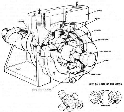
Each bearing has its own self-contained lubrication system which includes a gear driven oil pump (Roto Plunge Type T/GM/AR Special) mounted on the top half casing of the bearing. The pump, which is capable of delivering. 400 gal/ hour at a motor speed of 400 rev/min., takes a suction from the sump and discharges via an oil flow indicator (Arkon Type LFH.3) to the bearing stand pipe.
The Roto Plunge pump is illustrated in Fig 4. it consists basically of a pump casing containing a rotor in which two double-acting plungers, arranged at 90 degrees to one another, are operated by a square block carried on a stationary eccentric pin.
The pump is reversible, i.e. the pumping direction is constant irrespective of the direction of rotation of the pump. This is effected by means of a device, which, when the pump is reversed, automatically holds the eccentric pin stationary after friction has caused it to turn with the rotor for the first half revolution of the pump.
The pump casing, of aluminum bronze, is cast with suction and delivery ports at the top and with an open free end for closing with an end cover, it is machined to receive the combined rotor and drive shaft and an inner cover, also to provide suction and delivery channels, a bearing for the drive shaft and a pump stuffing box.
The plungers are housed at 90 degrees to one
another in the rotor and are slotted at the centre as illustrated to engage the square block. The latter is mounted over the eccentric pin and held in a recess on the inner end of the rotor, by a bearing plate dowelled and bolted to this end of the rotor. The bearing plate is supported on a journal, which, together with the eccentric pin, forms an integral part of the inner cover.
The inner cover is shaped to fit inside the casing cover and is free to turn on the protruding end of a pin which is pressed into a hole through the casing cover and made oiltight by means of an "O" ring.
When the pump starts revolving the inner cover is carried round through friction until a lug formed on its outer end comes into contact with one of two stops formed on the inside of the casing cover. Similarly, when the pump is reversed the inner cover is carried round until the lug comes into contact with the other stop on the casing cover. As the arc of movement between the stops is 180 degrees it therefore follows that a constant pumping direction is maintained irrespective of the direction of rotation of the pump.
15-15
All internal parts of the pump are lubricated by leakage oil from the pressure spaces and all are made of various grades of cast iron with the exception of the cover pin which is of steel.
Drive for the oil pump is taken from a gear wheel bolted to a collar on the armature shaft. The wheel is made in halves and located by fitted bolts and bushes to give correct alignment. The gear wheel drives a pinion housed within the bearing top casing, the gears being lubricated by oil fed from a small pipe attached to the bearing stand pipe.
The pinion drive, of flexible design, is keyed to an athwartships skew gear shaft, axially located by two ball bearings. The bearings are fitted in removable housings, each housing being provided with a Tecalemit grease nipple. To enable the skew gear drive to be inspected, a small door is provided in the top of the casing.
The outboard end of the skew gear drive shaft of the after motor bearing is connected by a flexible coupling to the oil pump whilst the inboard end of this shaft is connected by a second flexible coupling to a GEC TachoGenerator. In a similar manner the outboard end of the skew gear drive shaft of the forward motor bearing is connected to a Harding and Rhodes revolution counter and inboard end to the oil pump.
15.05 SHAFT BRAKES (Fig 5)
A shaft brake is provided on each run of propelling shafting at the junction of the after coupling of the thrust shaft and the forward coupling of the intermediate shaft. Each brake is designed to halt a trailing shaft and prevent it from turning when the other shaft is turning at speeds up to a maximum of 400 rev/min.
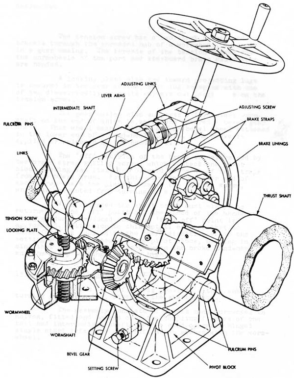
The brake assembly consists of two ferodo lined hinged straps of forged steel which embrace a 20 in. diameter brake drum fitted over the rim of the connected coupling.
The lower end of each strap is located by one of two fulcrum pins incorporated in a pivot block casting bolted to the deck immediately beneath the brake drum. The upper ends of the brake straps are coupled together by an adjusting screw complete with links and pins. The outboard link is also connected to an athwartships lever arm, the outboard end of which is connected by a short link to a tension screw as illustrated.
15-16
Fig 5 SHAFT BRAKE
15-17
The tension screw has a two start thread and travels through the threaded hub of a wormwheel, supported in a gear casing. The threads of the tension screws and the wormwheels of the port and starboard brake assemblies are handed.
A locking plate with two inward projecting lugs is secured to the gear casing, each lug engaging with one of two diametrically opposite keyways cut lengthwise on the tension screw.
The gear casing also supports a five start worm-shaft on the end of which is keyed and secured a bevel gear wheel. This wheel meshes with a second bevel wheel attached to the lower end of a handwheel spindle. The brake is applied or released by the handwheel.
The 'off' position of the brake is determined by two brake strap setting screws which contact the pivot block casting and limit the outward movement of the straps from the brake drum. For this purpose the lower end of each strap has a toe piece to carry the setting screw, which is prevented from turning by a lock nut.
When released the shaft brake must always be returned to the 'off' position, the speed of the handwheel being gradually reduced when the 'full off' point is approached. Attention to this detail ensures that no undue force is applied in the 'off' direction after the setting screws have touched the pivot block, bearing in mind that the velocity ratio between the brake handwheel and the strap setting, is very high.
15.06 SHAFT TURNING (Fig 6)
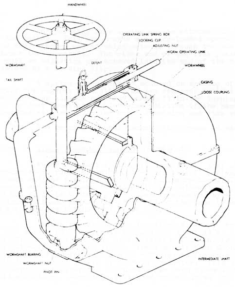
Each run of shafting is provided with a shaft turning gear assembly, sited in the shaft space.
The assembly consists of a left hand wormwheel in halves, fitted and bolted over the coupling flanges of the tail and intermediate shafts, and a hand operated hinged single start left hand wormshaft which meshes with the worm-wheel.
15-18
FIG 6. SHAFT TURNING GEAR
The gearing is housed in a casing made in halves, the top and bottom halves being secured together by six bolts and nuts, four of which are fitted.
The wormshaft is supported at its bottom end by a wormshaft bearing, through which passes a pivot pin, carried in bosses cast integral with the lower half of the casing. The upper end of the wormshaft protrudes through a slot cut in the top of the casing to carry a handwheel.
15-19
An operating link spring box is attached to the top of the casing. This box houses a spring-loaded operating link the outboard end of which extends through the box to embrace the wormshaft. The other end of the link passes through an adjusting nut screwed into the end of the box and retained by a locking clip.
A spring-loaded detent mounted on the top of the spring box engages with either of two recesses drilled in the operating link to hold the wormshaft in the turning gear
'in' or 'out position. Clockwise rotation of the handwheel turns the main shaft in the ahead direction and vice versa.
The gearing is well packed with grease on assembly.
15.07 STERN TUBES AND GLANDS (Plate 4)
Where the tail shafts extend outboard they pass through stern tubes of welded steel construction, flanged at each end and forming part of the hull structure. The forward end of the tube is welded to the bulkhead at frame 107 and supports a stern gland assembly attached by a ring of 1 1/4 in. studs and nuts. The after end of the tube is welded to a transverse bulkhead at frame 109.
Within the stern tube is welded a liner, the bore of the after end of which is stepped and machined to a nominal bore of 13.625 in. over a length of 10 in. from the outboard end of the liner. The liner is then machined slightly tapered for a length of 4.75 in. to finish along a 10 in. parallel length of 13.5 in. diameter. This machining is carried out after the stern tube has been assembled in the hull structure. Each tube is tested to 400 lb/sq in.
A stern tube bush, made in halves, is fitted in the liner. The bush is whitemetal lined, bonding of the lining being assisted by a number of tapped holes staggered along the length of each half bush. The horns of the two half bushes are arranged to butt on a slanting joint designed to enable the top half to be withdrawn first. The bottom half is then removed after the weight of the shaft has been eased.
15-20
Large Plate on Separate Page
TAIL SHAFT BEARINGS, STERN GLAND AND PROPELLER Plate 4
15-21
The bush is bored out about a centre concentric with the centre line of the shafting. The whitemetal lining of the bush is then bored 0.0066 in. above the centre line of the shafting so that the shaft is concentric with the bush when the shaft is lying on the bottom lining.
The bush is flanged and bolted to make a face to face joint with the after end flange of the stern tube by twelve 3/4 in. BSF square neck studs and nuts. Initial breaking out of the half bushes is achieved by four 1 in. BSF starting bolts which screw into holes in each half bush flange. Two tapped holes are provided in each half bush for lifting eye bolts.
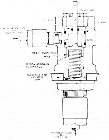
The bearing bushes are lubricated with grease supplied from a grease gun which consists of a container fitted with a screw operated plunger and handlever. Grease from the gun passes, via a common pressure gauge and a measuring valve for each bush, to a stop valve screwed into the top of each stern tube above the bush. From the stop valve the grease passes to the bearing surfaces via an annular groove machined around the outside of the bush, and two radial holes drilled through the bottom of the bush. The measuring valves (Fig. 7) ensure that each bush receives an equal and measured amount of grease on each occasion of working the grease gun. When in dock initial charging and proving of grease to the stern tube bearing is carried out with the internal parts removed from the measuring valve body and the valve cover replaced by the blank cover provided.
The weight of one stern tube bush is 11 cwt 14 lb.
The stern gland assembly consists of a gunmetal bulkhead casting to which is secured a gland stuffing box containing seven turns bf Sterntite square section packing. A gunmetal lantern ring is inserted between the third and fourth turns of gland packing.
The glands are lubricated with grease supplied from Tecalemit spring feed reservoir lubricators one mounted as near as possible to each stern gland. The lantern ring is located by a locking plug, the bottom half of the ring being drilled to register with a test plug screwed into the bottom of the stuffing box.
The gland packing is compressed by a flanged gland ring tightened by four hexagon headed pinion nuts screwed on to four gland studs as illustrated.
15-22
FIG 7. GREASE MEASURING VALVE
With the exception of the bulkhead casting and the stuffing box all of the main components of the stern gland assembly are made in halves to enable the assembly to be dismantled with the shaft in place. The halves of the gland ring are secured together by 3/4 in. BSF fitted bolts and nuts.
The gland can be cooled by sea water supplied from the after services via a SDNR valve, the water passing to an inlet connection on the top of the bulkhead casting. A drain cock is provided on the bottom of the casting. Weights: - Bulkhead casting - 4 cwt; stuffing box - 3 cwt; Gland - 2 cwt, 2 qr. 4 lb.
15-23
15.08 "A" BRACKETS AND BEARINGS
The weight of the propeller and the after end of the tail shaft are supported by an outboard bearing sited beneath No. 7 main ballast tank.
The hearing is held in position by an "A" bracket assembly the forged steel shell of which houses a bearing bush. The bracket arms, an upper and a lower of stream line section, branch from the shell and are welded to the hull structure.
The "A" bracket shell is machined to a nominal bore of 14 in. and is stepped, the bore slightly increasing in diameter from aft to forward to accommodate the flanged bearing bush.
The bush is split to form a top half and a bottom half, the horns of which butt when assembled to make a slanting joint so designed to facilitate the withdrawal or replacement. of the bush. Initial breaking out of the two half bushes is achieved by four 1 in. BSF starting screws, two tapped holes provided in the flange of each half bush.
Six grooves of dovetail section are cut lengthwise on the inside of each half bearing bush for the reception of bearing strips, each strip comprising five 9 in. lengths of Mintex. The strips are located axially by two gunmetal retaining rings in halves, fitted in circular recesses machined in the bush, one towards the after end of the bush and the other towards the forward end. Each retaining ring is prevented from turning by two locking pins screwed into the back of the bush and entering holes drilled in each half ring. After assembly in the bush the Mintex is bored to give a running clearance with the shaft of 0.0185 in. plus a swelling
clearance of 0.0241 in.
Each "A" bracket shell is provided with a plugged hole through which a poker type micrometer gauge is inserted for taking the 'wear down' of the bearing lining when the vessel is water borne.
Each "A" bracket bearing bush weighs 1 ton - 1 cwt -
4 lb.
15-24
15.09 PROPELLERS (Plate 5)
The propellers, which are three bladed and made of aluminum bronze, are manufactured by Messrs J. Stone and Co. (Charlton) Ltd. The port propeller is left handed, the starboard right handed.
The propeller nut is conical and for lightness the part aft of the internal thread is made hollow being strengthened by four internal webs. The thread is right handed on both shafts. The nut has six flats machined on its forward end to fit a propeller spanner. The flats are covered with six stop plates machined on their outside to maintain the conical shape of the nut and so form a continuous fair surface with the propeller boss. Lech stop plate is secured to the nut by two countersunk screws. Two of the plates have small end lugs which enter suitable recesses on the propeller boss and so lock the nut in position. To assist in the removal of the stop plate securing screws, each screw has an axial hold drilled through it to receive an 'Easy - out'. The hole is normally filled with wax.
A groove is cut around the propeller nut just abaft the stop plate so that a strop can be passed to take the weight of the nut when it is being removed. The nut is also drilled and taped to receive an end cap. This cap serves as an air vent and can be replaced by an adaptor when testing the nut to its water pressure test of 400 lb/sq.in. Both propeller nuts are conspicuously marked 'Right Hand Thread'.
Two keys, fitted in diametrically opposite keyways, locate the propeller on the tapered end of the tail shaft. Each key is secured to the shaft by two cheese headed countersunk screws and is drilled and tapped to take two starting screws.
The forward end of the propeller boss is counter-bored to form the stuffing box of a gland which is packed with a dexine ring held in position by a gland ring. The latter is secured by eight square neck studs, nuts and split pins. The after face of the propeller boss has two diametrically opposite holes drilled and tapped into it for taking a pair of withdrawing bolts. Another hole is drilled and tapped into the boss near a point vertically
above the centre of gravity of the propeller to take a
lifting eye bolt. The hole is normally plugged with a slot headed bolt.
Propellers can be removed with the vessel afloat.
15-25
PROPELLER WITHDRAWING GEAR
PLATE 5
15-26
Propeller details:
Weight
21.5 cwt.
Diameter
7 ft.
Pitch
6 ft. 2. 1/2 in. (max)
Developed area to boss (3 blades)
20.86 sq ft.
Blade area ratio
0.542
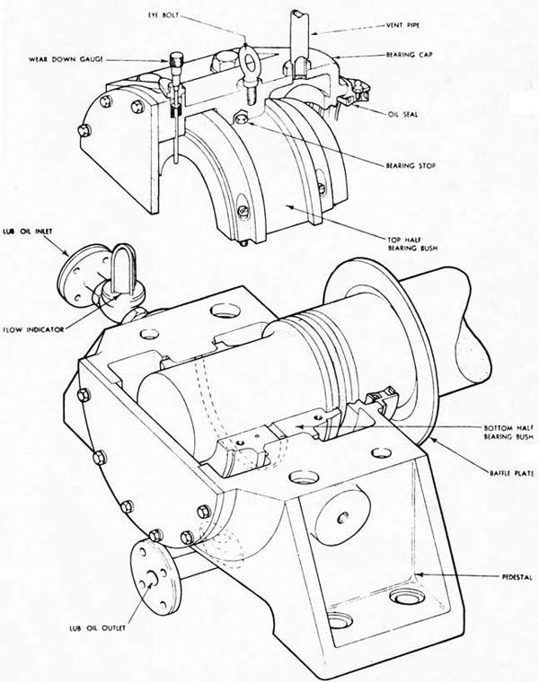
15.10 DIESEL-DRIVEN GENERATOR BEARING (Fig. 8)
A pedestal bearing is fitted to the after end of each diesel-driven generator, the forward end of the armature shaft being directly coupled to the stub shaft on the after end of the diesel crankshaft. The bearing is supplied with oil from the engine forced lubrication system via a regulating valve, a pressure gauge and flow indicator. Oil from the bearing flows by gravity to the engine drain oil tank via a thermometer and a stop valve.
The bearing bush, of gunmetal, is made in halves and whitemetal lined to a thickness of 0.010 - 0.015 in. over an arc of 120 degrees in each half. It is bored to give a diametral clearance of 0.010 - 0.015 in. with the armature shaft.
A flange type Weston split oil seal is provided on the forward end of the bearing, the seal housing secured by countersunk screws to the bearing cap and pedestal. This seal bears on the armature shaft and prevents seepage of oil along the shaft from the bearing to the interior of the generator.
To prevent oil mist penetrating the interior of the generator a baffle plate is fitted around the armature shaft and bolted to the after end plate of the generator casing.
To prevent damage to the bearings by currents flowing along the shaft from the generator the following items are electrically insulated: the base of the pedestal and its holding down bolts and the flanges and securing bolts of the oil inlet and outlet connections. In addition the distant reading thermometer is provided with an insulated capillary and an insulated flexible length of tubing is inserted in the vent pipe between the bearing and the first clip on the ship's structure.