C.F. 'O' Class Submarines - Miscellaneous Systems and Equipment, describes ten of the systems aboard Oberon class submarines.
In this online version of the manual we have attempted to keep the flavor of the original layout while taking advantage of the Web's universal accessibility. Different browsers and fonts will cause the text to move, but the text will remain roughly where it is in the original manual. In addition to errors we have attempted to preserve from the original, this text was captured by a combination of optical character recognition and human typist. Each method creates errors that are compounded while encoding for the Web. Please report any typos, or particularly annoying layout issues with the Mail Feedback Form for correction.
Fresh water for domestic purposes is stored in six tanks, the capacity and location of each tank being as follows:
Tank No.
Capacity (gal)
Location (frame Nos.)
Tank No.
Capacity (gal)
Location (frame Nos.)
1
2040
34 - 42 (P)
4
1058
49 - 53 (p)
2
1200
42 - 47 (P)
5
1058
49 - 53 (s)
3
1245
42 - 47 (S)
6
2775
87 - 97 (S)
Nos. 1, 2 and 3 tanks are common through two 2 in. bore syphon pipes, one of which runs from the bottom of No. 3 to the top of No. 1. Nos. 4 and 5 tanks ore also common through a similar syphon pipe which runs from the bottom of No. 5 to the top of No. 4. A strum box is fitted at the lower end of each syphon pipe.
Fresh water is embarked at two filling stations each comprising a hose connection fitted flush with the casing, an inboard hull filling valve and a valve chest. A 15 p.s.i. relief valve and a pressure gauge are fitted in each filling line between the hull valve and the valve chest. From the forward of these two filling lines a branch pipe provides, through a SDNR valve, a cross-connection between the fresh and distilled water systems. This cross-connection enables the fresh water tanks to be topped up from the distilled water system but not vice versa.
From the forward valve chest two filling pipes are led, one to No. 1 tank and the other to No. 4 tank. From the after valve chest a filling pipe is led to No. 6 tank. The filling pipes terminate in strum boxes near the bottom of the tanks, and also serve to supply the freshwater main via the valve chests. Pressure in the freshwater main is maintained by putting a slight air pressure into the tanks/tank in use.
9-2
Large Plate on Separate Page
Fresh and Distilled Water System Fig 17
9-3
9.11 FRESH WATER SYSTEM (CONTD)
A shut off valve, operated by rod gearing from either the main store or the forward end of the control room, is fitted in the filling pipe to No. 4 tank.
From the valve chests the fresh water main is led overhead to the FTPL and ATR, a strainer and a flowmeter being fitted between each valve chest and the main.
In the FTR a tapping off the main, supplies a three gallon ready use tank fitted with a 15 lb/sq. in. relief valve and where the main terminates in this compartment, a stop valve and a connection for a hose incorporating a jet and spray nozzle is provided for fire fighting purposes.
A branch from the main in the diesel - generator room is led to a fresh/distilled water distribution valve chest and another tapping off the main in this compartment is used for topping up the sealing water reservoir of the ballast pump air pump.
Where the main passes through a major bulkhead a shut off valve is fitted on either side. Each valve is tested to
135 lb/sq.in. but is designed to withstand a pressure 350 lb/sq.in. without appreciable leakage. Other items supplied from the main are illustrated in Figure 1.
In living spaces the main is lagged with 1/2 in. thick fibre glass flexible mat covered with light canvas to prevent condensation.
After installation the main is tested to 70 lb/sq.in. All tanks are tested to 15 lb/sq.in. and are coated with a bitumastic compound.
All freshwater tanks are fitted with a dip rod and Nos. 3, 5 and 6 with combined vent and blow cocks. Reduced air for blowing the forward two groups of tanks is taken from No. 2 HP air ring main cross-connection via two reducers arranged in series to give a final pressure of 10 lb/sq.in. A 0-200 lb/sq.in. pressure gauge is fitted between the reducers and a 0-50 lb/sq.in. pressure gauge and a 15 lb/sq.in. relief valve on the outlet side of the final reducer. The blowing arrangements for No. 6 tank are similar to those for the other tanks, the supply of air being taken from No. 6 HP air ring main cross-connection. Nos. 1, 2 and 4 tanks are provided with inboard vent cocks only.
To supplement the amount of fresh water carried on board a Caird and Rayner vapour compression type distilling plant is installed in the diesel generator room.
9-4
9.12 DISTILLED WATER SYSTEM (Fig. 1)
Distilled water for topping-up the battery cells, cooling the diesel generating engines and filling the battery cooling system is stored in three tanks, namely, a main distilled water tank (1,925 gallons) sited beneath No. 1 battery (frames 34-42S), an engine-cooling distilled water tank (471 gallons) sited on the starboard side of the main generator room, and a distiller-made water tank (154 gallons) sited immediately abaft the engine cooling tank. The latter tank receives pure water produced by the distiller.
The main distilled water tank is connected through a shut-off Valve to a distilled water main which extends fore-and-aft from the accommodation space to the main generator room terminating in the distilled/fresh water distribution chest. The foremost end of the main is fitted with a hose connection, pressure gauge, shut-off valve and a 15 lb/sq.in. relief valve for shore filling purposes.
The distribution chest houses three SD NR valves and one S.D. valve, is also connected to the fresh water main, the distiller-made tank and the engine coiling tank. The arrangement of the chest enables the following transfers of water to be carried out:
(a) From the fresh water main to the engine cooling tank.
(b) From the distiller-made tank to the engine cooling tank.
(c) From the distiller-made tank to the main distilled water tank.
(d) From the distiller-made tank to the fresh water tanks via the distilled/fresh water cross-connection.
(e) From the distiller-made tank to the fresh water main direct.
Two athwartships branch pipes are led from the main and supply water for "topping up" the lain battery cells. From each branch supply pipes (P and S) fitted with shut-off valves are led forward into each battery section. Two flexible leads connected to each supply pipe distribute water to the cells, each being provided with an insulated nozzle. The after branch pipe also supplies the battery cooling system through shut-off valves, and is fitted with a Salinometer.
9-5
9.12 DISTILLED WATER SYSTEM (CONTD)
Where the main passes through a watertight bulkhead, a shut-off valve is fitted on either side. Each valve is tested to 135 lb/sq.in., but is designed to withstand 350 lb/sq.in. without appreciable leakage.
All metallic pipes, valves and fittings in the distilled water circuits are of copper, tinned internally.
All tanks are tested to 15 lb/sq.in. After installation, the piping of the system is tested to 70 lb/sq.in. Where the main passes through living spaces it is lagged with 1/2-in. fibre glass flexible mat, covered with light canvas to prevent condensation.
The main distilled water tank is fitted with a combined vent and blow cock, and is blown from the same station as Nos. 1 - 5 fresh water tanks.
The distiller-made tank is fitted with a combined vent and blow cock, and is blown from the same blowing station as No. 6 freshwater tank.
The engine-cooling tank is provided with an inboard vent only.
9-6
C.F. 'O' CLASS SUBMARINES
MISCELLANEOUS SYSTEMS AND EQUIPMENT
PART 2 - SANITARY SYSTEM
9.21 INTRODUCTION
Four slop drain tanks are fitted in various positions in the submarine to collect drainage from washhand basins, sinks, showers and bathroom decks, this then remains in the tanks until operational circumstances permit it to be discharged overboard.
One sewage tank is fitted to collect sewage from the heads, this also remains in the tank until it can be discharged overboard.
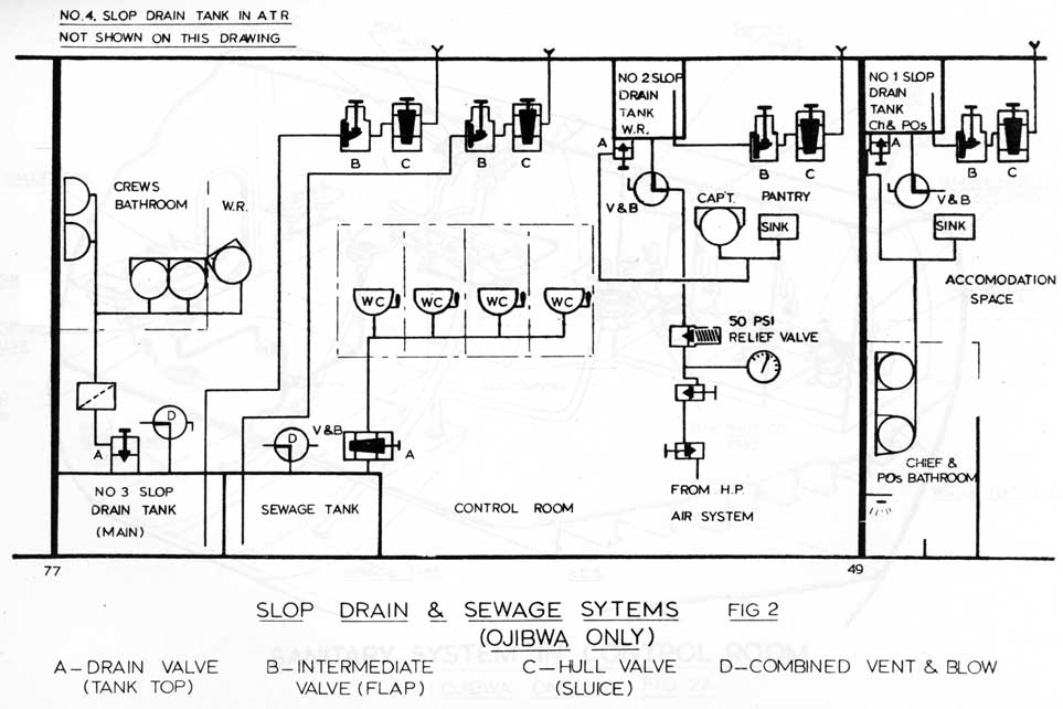
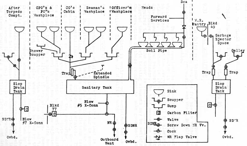
9.22 GENERAL (Fig. 2)
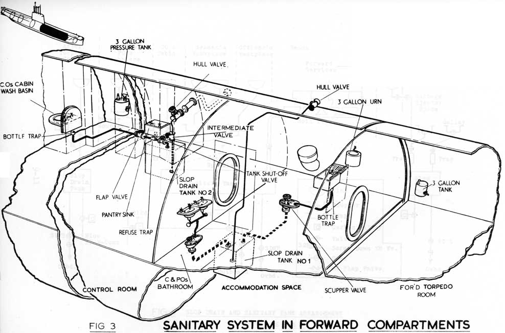
A. No. 1 Slop Drain tank is located in the Coxswain's store and collects the drainage of the Chief and P.O.'s bathroom, pantry, shower and garbage ejector vent.
B. No. 2 Slop Drain tank is located below the W.R. pantry, and collects the drainage of W.R. pantry sink and CO's wash basin.
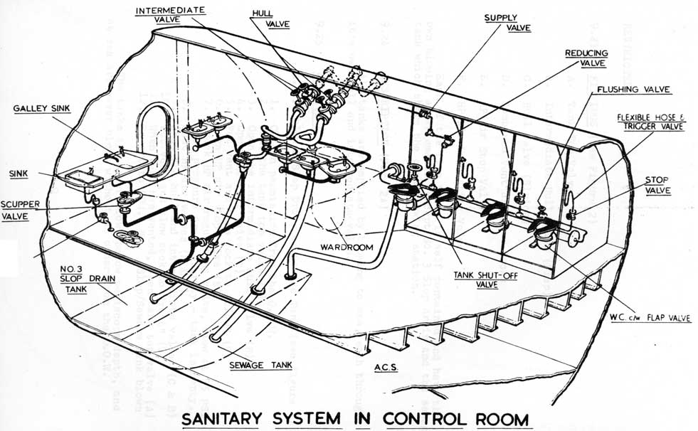
C. No. 3 Slop Drain tank, this is the main tank and is situated under the deck of the ACS immediately forward of the E.R. bulkhead, collects drainage from W.R.
and crews bathrooms and galley.
D. No. 4 Slop Drain tank is fitted in the Engineers Store and takes the drainage from the After Mess pantry.
E. Sewage tank, located immediately forward of slop drain tank number 3.
In "ONONDAGA" and "OKANAGAN", slop drain tank number 3 and the sewage tank have been combined to form one tank, called the sanitary tank. (Fig. 4)
9-7
9-8
(OJIBWA ONLY)
FIG 2A
9-9
9.23 FITTINGS (See Figure 2)
A. Tank Top Valve
B. Intermediate Hull Valve (Flap)
C. Hull Valve (Sluice)
D. Combined Vent and Blow Cocks
E. HP Air Stop Valve
F. HP Air Regulating Valve
Each of the five tanks is self contained and have their own blowing arrangements, except No. 3 Slop drain and the sewage tank which share the same blowing station.
9.24 DESCRIPTION (Fig. 2A)
All tanks are emptied by blowing to sea, each through it's own hull and intermediate valve.
9.25 OPERATION
A. To blow a Slop Drain or Sewage Tank (see figure 2)
1. Obtain permission from the O.O.W.
2. Shut the tank top valve (A)
3. Open the intermediate hull valve (B)
4. Open the hull valve (C)
5. Put vent and blow cock to "blow" (D)
6. Open HP air stop valve (E)
7. Crack HP air regulating valve, blow at 35 PSI (F)
When pressure drops sharply - tank is empty.
8. Shut HP air valves (E & F)
9. Shut the hull and intermediate valves (C & B)
10. Put vent and blow cock to "vent" (D)
11. When tank has vented, open tank top valve (A)
12. Report to OOW. No. Slop/Sewage tank blown
The tanks are never blown below periscope depth, and at sea are never blown without an order from the O.O.W.
9-10
9-11
FIG 4
SLOP DRAIN AND SANITARY TANK ARRANGEMENT
SS 73 & 74
9-12
C .F . 'O' CLASS SUBMARINE
MISCELLANEOUS SYSTEMS & EQUIPMENT
PART 3 - THE DISTILLING PLANT (TYPE D)
9.31 GENERAL DESCRIPTION
The Caird and Raynor Type 'D' vapour compression distilling plant has been designed for use in vessels where steam is not generated for propulsion and where no alternative supply of steam is available.
The heat required to evaporate the sea water, from which the distilled water is produced, is applied initially to the sea water in the evaporator shell by electrical heating elements. A compressor is incorporated in the plant to withdraw vapour from the evaporator shell and to discharge it at a pressure to the condenser. By this means the amount of heat required to boil the water is reduced. Once the plant has been started the electric heating elements may be switched off, with the exception of those required to make good heat losses from condensation and radiation.
The plant is entirely self contained and is specified to deliver 22 gallons of distilled water per hour.
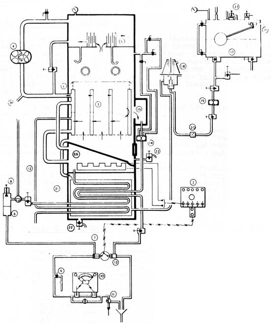
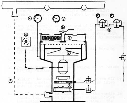
9.32 OPERATION (Fig. 5)
Production of distillate from this plant is the result of a process of heat exchanging. Feed water is supplied to the Feed Stabiliser from a header tank. This tank can be pressurised while snorkelling to simulate surface conditions inside the tank. The feed stabiliser valve is diaphragm operated. The diaphragm is balanced between an upper and lower spring, the upper side being subject to ambient air inside the submarine, and the lower to conditions inside the distiller shell. Rate of flow through the stabiliser is consistent with the output of distillate and brine discharge. Level in the shell can be adjusted by altering the spring tension on the diaphragm, but, having been set by the maker should require little if any alteration. Feed water from the stabiliser enters the bottom of the shell and is led into the brine and distillate cooler where it is heated by the brine and distillate. It is then led via a duct to the space around the fresh water chamber, where it is further heated by the heaters in this chamber. It then passes upwards through the heating unit, (inside the condenser tubes) further heat being imparted by the steam being condensed, and finally flashes into steam under a vacuum (2 - 5 in.) created by the vapour compressor. The steam separator is a multiple flow type, and drain pipes are fitted to the baffle and baffle platform.
9-13
FIG 5
TYPE 'D' DISTILLING PLANT
9-14
9.32 OPERATION (CONTD)
The snorkelling effect on the diaphragm of the feed stabiliser is to cause it to lift, and therefore admit slightly more feed water into the shell. The input of extra water prevents the plant from surging due to added vacuum effect. The heating chamber is also subject to the ambient air conditions in the S/M via the vent pipe which is led to bilge. The chamber is portable in earlier plants and is cast integral with the shell in the later plants.
A weir prevents the possibility of the brine pump removing too much water from the shell.
Should the vapour compressor discharge temperature reach 285 degrees F. or, the freshwater chamber reach 245 degrees F. the motor for the combined pumps and vapour compressor, and the heaters, will automatically cut-out.
Note: Feed water supply to the feed stabiliser is opened u: when filling the shell prior to starting, but is then shut dawn until the plant is put into production. The freshwater cooler and chamber must he primed with distilled (or fresh water) but NOT SALT WATER prior to starting the plant.
9.33 MAKERS TRIAL DATA
Evaporator shell pressure
3 to 5 in. Hg.
Compressor discharge pressure
2 to 4 P.S.I.
Compressor discharge temperature
260 to 280 Deg. F.
Distilled water output
18 to 22 g.p.h.
Distilled water temperature
36 to 44 g.p.h.
Brine discharge
130 deg. F.
Feed water temperature
60 deg. F.
Salinometer reading
0.03 to 0.3 gr.p.g,
Motor speed
2750 r.p.m.
Compressor speed
2900 r.p.m.
Pump speed
1500 r.p.m. (equal to 90 working strokes per min.)
9-15
C.F. 'O' CLASS SUBMARINES
MISCELLANEOUS SYSTEMS AND EQUIPMENT
PART 4. - AIR CONDITIONING, VENTILATION AND REFRIGERATION
9.41 INTRODUCTION
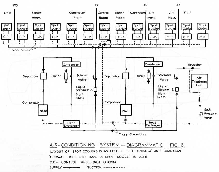
Air conditioning machinery is fitted to regulate the temperature and humidity of the air in the submarine. Cool dry air is distributed throughout the ship to create comfortable living conditions and to provide the best operating conditions for certain electronic equipment.
A. Description
1. Supply
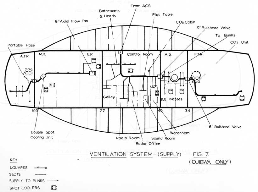
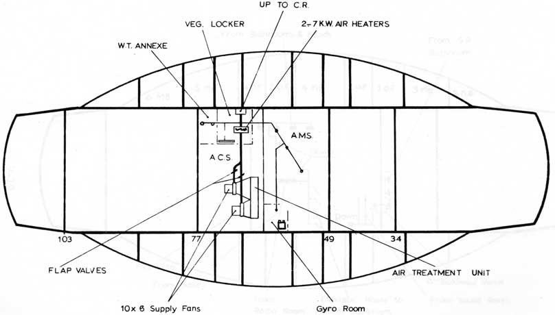
Two air conditioning plants are fitted, both in the ACS. The forward plant supplies refrigerant to a Main Air Treatment Unit, and the after plant supplies refrigerant, through a FREON MAIN, to 13 air treatment units (SPOT COOLERS) situated in selected positions throughout the ship. A steel ventilation trunking runs from the main air treatment unit, up into the CR flat and forward into the F.T.R. Two 10" x 6" fans take a suction over the Main Air Treatment unit where the air is cooled and dried, and discharge into the trunking. Branches from this trunking run into messes, bunk spaces, machinery compartments, stores etc., and it can be shut off where it passes through bulkheads. For heating purposes, two 7KW electric heaters are fitted on the discharge side of the 10" x 6" fans. (Fig. 8)
Another fan, a 9" axial flow, takes a suction from the vicinity of the ER door and discharges into another trunking, over a double spot cooler installed in the trunking and into the A.T.R. (Fig. 7)
The remainder of the spot coolers have their own fans and cool in their own immediate vicinity. They are also fitted with electric heaters. (Fig. 6)
9-16
9-17
9-18
Ventilation System (Supply)
Layout in ACS and AMS
Fig 8 (Ojibwa Only)
9-19
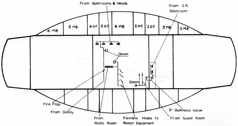
Ventilation System-(Exhaust)
Fig 9
(Ojibwa Only)
9-20
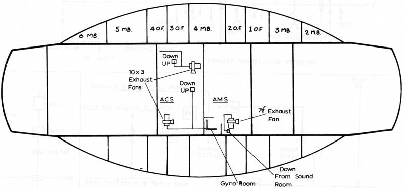
VENTILATION SYSTEM (EXHAUST)
FIG 10
Layout in AMS/ACS
(Ojibwa Only)
9-21
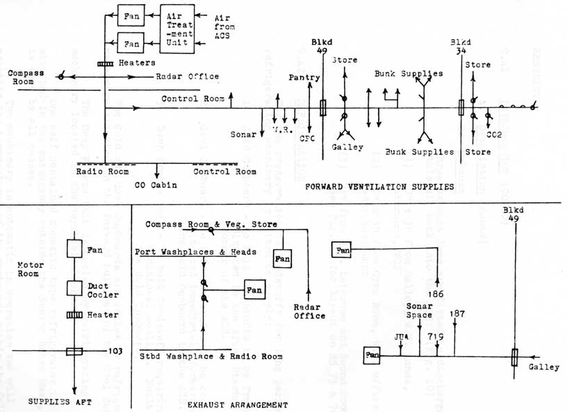
VENTILATION - SUPPLY AND EXHAUST - SS 73 & 74
FIG 11
9-22
9.41 INTRODUCTION (CONTD)
A. Description (Contd)
2. Exhaust
Three exhaust fans are fitted to discharge stale air back into the ACS: (Fig. 10)
(1) 10" x 3" from Galley, W.T. Annex, Bathrooms, WCS
(2) 10" x 3" from Gyro Room, W.T. office, Radar Equipment
(3) 7 1/2" from S. R. bathroom and Sound Room. (See Fig. II for layout on SS 73 & 74)
9.42 REFRIGERATION
For the preservation of foodstuffs for long periods, refrigerating machinery is fitted to supply:
1. Cold Cupboard - to hold foodstuffs to be frozen. Situated in the After Starboard corner of the ACS.
2. Cool Cupboard - to hold foodstuffs to be cooled. Situated immediately forward of the Cold Cupboard in the ACS.
3. Deep Freeze Unit - to hold foodstuff requiring additional cooling. Built into the Cold Cupboard.
The Cold and Cool Cupboards are cooled by refrigerating machinery situated on the forward bulkhead of the Cool Cupboard.
The Deep Freeze Unit is cooled by refrigerating machinery located in the vegetable locker.
One self contained domestic type refrigerator is situated in the passageway outside the Senior Rates Mess, it is used by all messes.
The machinery is automatic in operation and will
maintain the temperatures of the cupboards within the following limits:
9-23
FIG 12 BULKHEAD VALVE
9-24
9.42 REFRIGERATION (CONTD)
a. Cold Cupboard 8°F - 14°F
b. Cool Cupboard 36°F - 44°F
c. Deep Freeze -10°F - 0°F
Temperature Gauges for the Cold Cupboard, Cool Cupboard and Deep Freeze Unit are situated in the ACS and are to be checked every hour.
In harbour these readings are to be recorded on the "below decks check off list" and at sea they are recorded in the Engine Room Register.
Cooling water from the refrigerating and air conditioning machinery is supplied from the After Services System, via the forward services using a power operated supply valve.
9-25
C.F. 'O' CLASS SUBMARINES
MISCELLANEOUS SYSTEMS AND EQUIPMENT
PART 5 - AIR PURIFICATION IN SUBMARINES
9.51 INTRODUCTION
A. When a submarine is submerged a gradual deterioration in the internal atmosphere conditions takes place which is brought about by the respiration of the Ship's Company.
Oxygen is consumed whilst Carbon Dioxide and
water vapour are given off and accumulate in the atmosphere. At the same time, heat is evolved by the bodies of the men in the submarine, and causes a rise in temperature. These effects, if not carefully controlled, will in time produce unpleasant working and living conditions and a gradual falling off in mental and physical efficiency.
The regulation of the temperature and humidity is known as AIR CONDITIONING and entails the use of apparatus which cools and removes moisture from the air.
The removal of carbon dioxide produced by the ship's company and the replacement of the oxygen consumed is called AIR PURIFICATION.
B. Physiology of Breathing
The human body is like a small engine. In order to perform work it must combine fuel (food) with oxygen, and in the process it produces a waste product, carbon dioxide. The more work to be performed the more oxygen must be breathed in and the greater the
amount of carbon dioxide which is produced. It is the increased amount of CO2 which must be breathed out which is the chief cause of an increased rate of respiration when performing heavy work.
C. Composition of the Atmosphere
Under normal conditions air is a mixture of approximately 79% nitrogen, and 21% oxygen, with a trace of carbon dioxide. At normal pressures nitrogen is inert and plays no part in the breathing process.
9-26
9.51 INTRODUCTION (CONTD)
C. Composition of the Atmosphere (contd)
If a group of men are enclosed in a space to which no outside air can gain access the percentage of oxygen in the space will gradually decrease and the percentage of carbon dioxide will gradually increase. The effects of this on personnel are shown below.
1. Percentage of Oxygen
Effect
18%
impairment of night vision; judgement begins to be impaired.
15%
judgement very seriously impaired.
11%
unconsciousness
2. Percentage of CO2
Effect
3%
1. increase in depth of respiration 2. power of exertion limited
4%
1. noticeable increase in depth of respiration even at rest 2. flushing and palpitations
6%
1. hard work virtually impossible
8% to 10%
1. unconsciousness
It should be noted that an increase of CO2 produces recognizable physical symptoms, while a lack of 02 is not readily apparent from observation of affected personnel.
D. Limit of Alertness
The figures of 18% oxygen and 3% carbon dioxide are defined as the limit of alertness. If this limit is reached for either gas, air purification must be started. In practice, graphs are available which indicate the time when air purification should be started for a given number of men on board. It is started in accordance with the graphs, or if the percentage of CO2 rises to 3%, whichever occurs first.
9-27
9.51 INTRODUCTION (CONTD)
E. Effect of Pressure Changes
The effects of Oxygen and carbon dioxide depend on the number of molecules of the gas breathed in. If the pressure of air containing a given percentage of CO2 is increased the actual amount of CO2 taken in at each breath will correspondingly increase, even though the percentage has not changed. Similarly, if the pressure of air containing a given percentage as oxygen is decreased, the actual amount of oxygen taken in at each breath will decrease although its percentage remains the same. Thus the adverse effects of CO2 in the air increase with an increase in pressure, while the adverse effects of a lack of oxygen increase with a decrease in pressure. Therefore, when determining the amount of CO2 in the submarine it is always necessary to relate the percentage of CO2 to the existing pressure, and it may sometimes be necessary to bleed air into the submarine to break a partial vacuum and ensure that the effective amount of oxygen in the air is sufficient.
F. Other Effects
1. Nitrogen Narcosis: As stated above nitrogen does not normally play any part in the breathing process. However, if air is breathed at high pressures some of the nitrogen is absorbed in the lungs, producing the effect known as nitrogen narcosis. Symptoms include a feeling of light headedness, and the voice becomes squeaky and high pitched. The condition is not serious and the symptoms disappear when the pressure is reduced.
2. Bends: If nitrogen is breathed at high pressure it tends to form bubbles in the blood stream, spinal cord and brain when the pressure is reduced, causing intense pain and possibly convulsions. This condition is known as "the bends" and must be corrected by re-compressing the victim and reducing the pressure gradually.
9-28
9.51 INTRODUCTION (CONTD)
G. Measurement of Atmospheric Deterioration
Atmospheric deterioration is measured by two methods:
1. INSTRUMENTS which measure oxygen and carbon dioxide content of the atmosphere.
2. CALCULATIONS, based upon certain assumptions as to the average human oxygen consumption and CO2 production.
H. Instruments
All submarines are supplied with carbon dioxide indicators to show the percentage of CO2 in the atmosphere, no satisfactory oxygen meters have yet been developed, however, oxygen depletion usually proceeds parallel with the increase of CO2, so a close estimate of the 02 percentage can be made.
In submarine escape when the air in the escape compartment is compressed by flooding, the reading of the CO2 indicator must be corrected for pressure and a special gauge (BUDENGERG GAUGE) is provided for this purpose.
J. Calculations
The percentage of 02 and CO2 for any time after diving can be calculated assuming that the initial percentages (on diving) are:
Oxygen - 20.8% Carbon Dioxide - 0.2%
and that:
each man uses 0.85 cu. ft. of 02 and evolves 0.72 cu. f.t. of CO2 per hour and the volume of breathable air is 32,000 cu. ft.
In an 'O' class submarine:
Oxygen generation should start after 15 hours dived, and CO2 absorption after 18 hours dived, assuming that snorkelling has not taken place during that time and the men are performing their normal duties.
9-29
9.51 INTRODUCTION (CONTD)
J. Calculations (contd)
If however a large pro portion of the ship's company is engaged in heavy work, the limits will be reached earlier. Therefore air purification should be started
(a) when the calculated time has elapsed or
(b) when the CO2 indicator shows 3%
WHICHEVER IS EARLIER.
K. Air Purification Equipment
Equipment consists of two CO2 absorption units
and through canisters, four per unit, each containing 15 lb. of soda lime.
Generation of oxygen takes place by burning candles of sodium chlorate and iron filings in a generator. They evolve almost pure oxygen (55 cu. ft.) with no toxic gases being given off.
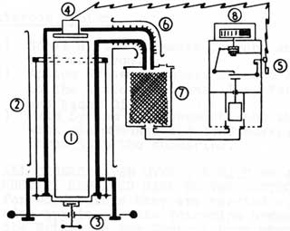
9.52 DESCRIPTION
A. CO2 Absorption Unit (Fig. 13)
1. CO2 Canisters - to hold soda lime (protestor). Canisters are sealed. When required for use the tops and bottoms are opened by special tin cutter. Canisters sit on rubber seats and are held in position by spring clips. Partly used canisters can be temporarily sealed by fitting a special blank which clips on to the rim of the canister.
2. Fan - to draw air through the CO2 canisters. Electrically driven and designed for silent running.
3. Flexible Hose - to connect the unit to ships ventilation system.
4. Vacuum Gauge - to indicate that the fan is drawing air through the canister at the correct rate. Gauge is connected to space beneath the canisters and will register the reduction in pressure (vacuum). The dial has a small green section where the needle must point for correct air flow.
9-30
9.52 DESCRIPTION (CONTD)
A. CO2 Absorbtion Unit (Fig. 13)
5. Fan Regulator - to adjust speed of fan.
6. Rotating Head - to ensure that each canister is used and replaced in rotation.
7. Air Motor and Turbine - to rotate the fan should electric power fail. Air motor (eccentric vane type) gives sufficient power. If air motor is at dead centre turbine is used for initial start and then shut off.
FIG 13 CO2 ABSORBTION UNIT
9-31
9.52 DESCRIPTION (CONTD)
A. CO2 Absorption Unit (Contd)
8. Reducing Valves - to reduce H.P. air fed direct from bottle ups (4000 lbs./sq.in.) Reduced in two stages (.000 - 500 PSI and 500 - 70 PSI)
9. CO2 Gauge - to indicate the pressure of air in the sub urine and the maximum allowable proportion (%) of CO2 content. CO2 content is measured on the Ringrose CO2 Indicator.
B. Oxygen Generator (Fig. 14)
1. Oxygen Candle - produces oxygen by self burning action. Kept in air tight container until required for use.
2. Burning Chamber - to contain candle whilst burning. Air cooling assisted by air space formed by outer cylinder.
13. Dropping Cover - to close end of burning chamber and provide convenient platform for loading candle when in lowered position. Cover, with copper asbestos joint, secured tight by screwed handle.
4. Heater Element (Electric) - to start burning action on candle. Glows red hot.
5. Switch - to switch on heater.
6. Cooling Fins - to cool hot oxygen as it leaves the burning chamber.
7. Filter - to extract traces of salt given off by burning candle. Safety disc fitted on inlet side in case of blockage.
8. Flow Indicator - to indicate that the candle is generating. \forked by plunger which rotates the indicator to show a green portion. The green portion will not show until plunger has moved enough to allow escape of oxygen into
the submarine (after about 5 min.). Movement of the plunger also switches off the heater.
9-32
9.52 DESCRIPTION (CONTD)
B. Oxygen Generator (Fig. 14)
Should the candle not ignite, the indicator will remain at white and after checking that the electric circuit is correct, the candle should be substituted, with a new one. After one candle has burnt, before another one can be ignited the cut-out must be re-set by a switch at the side. A candle burns for l hours and gloves should be worn when removing the spent candle. As the candle shrinks during burning it does not jam. The filter will accommodate 10 candles before being removed for washing in water, drying and replacing. Candle is made of Sodium Chlorate and iron filings. Should the indicator show half white and half green it means that the oxygen is leaking, either from the copper joint on the breech or the safety disc has perforated or a damp candle, thereby not creating enough pressure to turn the indicator completely to green.
Note: It is essential that the candle is perfectly clean when inserted in the generator. Therefore white cotton gloves are stowed in a locker near the generator, these should be worn when handling the candle. On removing the candle from its case the O.O.W. is to inspect it carefully for any flaws or dirt.
Any dirt on a candle will cause an explosion.
FIG 14 OXYGEN GENERATOR
9-33
C.F. 'O' CLASS SUBMARINES
MISCELLANEOUS SYSTEMS AND EQUIPMENT
PART 6 MISCELLANEOUS FITTINGS
9.61 A. Telegraphs
To transmit orders from the Control Room. Normal telegraph orders are used; STOP/SLOW/HALF/ FULL, AHEAD AND ASTERN. Diesel Generators have a separate order instrument, and a revolution telegraph is fitted. A grouper telegraph is fitted to order main motor groups.
B. Klaxon
A hooter used to indicate to the whole boat that the submarine is diving. The second blast of the klaxon is the executive order, due to the possibility of the Klaxon being operated accidentally. Three klaxon pushes are fitted, the tower push and lights have an isolating switch.
C. Night Alarm
A buzzer for alerting the ship's company for any emergency or Attack State. It has no EXECUTIVE meaning in itself, so is always followed by an order over the intercom.
D. Intercom System
(1) Sonar System connects Command and Control to Sound Room.
(2) Action System connects Command and Control to the Action Stations, i.e. Tubes, W/T and Radar Office.
(3) Main System interconnects the whole ship, with microphones and loudspeakers placed throughout the submarine.
N.B. ALL ORDERS GIVEN OVER THE MAIN OR ACTION SYSTEMS MUST BE REPEATED BACK TO THE CONTROL ROOM word for word before they are carried out. (This also applies to the Voicepipe orders given from the Bridge to the Control Room when surfaced).
9-34
9.61 MISCELLANEOUS FININGS (CONTD)
E. Echo Sounder
To measure the depth of water beneath the keel. The transmitter sends a sound wave downwards, and the reflected wave is picked up by the Receiver. The time taken is used by an electrical recorder to indicate the depth. It must never be operated at sea without the Captain's permission.
F. Depth Gauges
Necessary to enable the pilot to keep an ordered depth in feet. Operated by sea pressure. Also fitted in areas where knowledge of depth is required - e.g. engine room, W/T office, wardroom, C.O.'s cabin.
G. Search Periscope
A large binocular periscope which incorporates:
(1) High/low power magnification (6 and 1 1/2 times respectively)
(2) Sky search
(3) Split image type range finder
(4) A radar aerial
(5) Power training (roundabout)
H. Attack Periscope
A monocular periscope which is used in the closing stages of an attack. It incorporates:
(1) High/low power magnification (6 and 1 1/2 times)
(2) Sky search
(3) Split image type range finder
(4) Sextant
Both periscopes are fitted with coloured filters which can be used to eliminate glare from the sun. The search periscope has an adaptor to take a camera for photographic reconnaissance.
9-35
C.F. 'O' CLASS SUBMARINES
MISCELLANEOUS SYSTEMS AND EQUIPMENT
PART 7 VALVES AND HANDWHEELS
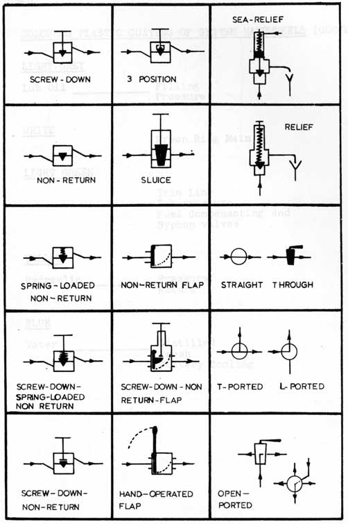
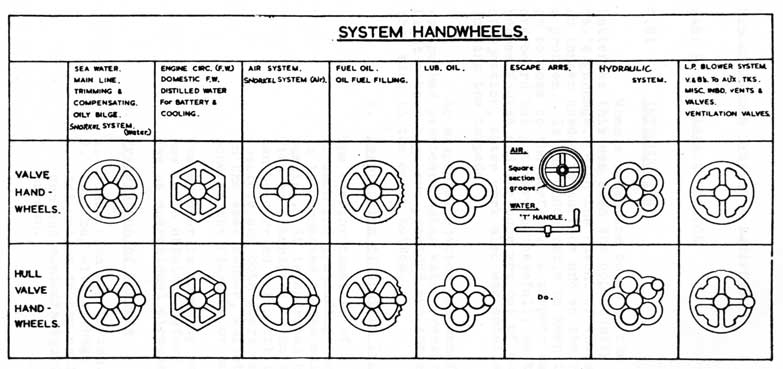
9.71 GENERAL
Fig.15 shows the types of valves and cocks used in 'O' class submarines.
Fig.16 shows the shapes of the handwheels used on the valves, each system having a different shape to make recognition easy.
Hull valve handwheels have a ball moulded on the
rim.
The handwheels are also coated with coloured plastic, once again each system having its own colour.
9.72 COLOURED PLASTIC COATING OF SYSTEM HAND WHEELS
RED
Air
H.P.
L.P.
Engine Start
Battery Ventilation
All Vents
BLACK
B.I.B.S.
Air Aided Escape
METALLIC GREY
Fuel
Subsequent
Supply from Snap Tank to A.S.R.I.'s
DARK GREEN
For'd Services
After Services
Fuel first filling
Main line and main line battery cooling
Oily bilge
Snort induction drain and floods
All torpedo tube drains
H.P. Air compressor cooling water
9-36
FIG 15
TYPES OF VALVES & COCKS
9-37
9.72 COLOURED PLASTIC COATING OF SYSTEM HANDWHEELS (CONTD)
LIGHT GREY
Lub Oil
Filling Pressure
WHITE
Freon Ring Main
LIGHT GREEN
Trim Line
Sub-pressure
Fuel Compensating and Syphon valves
YELLOW
Hydraulic
Pressure Return
BLUE
Water
Distilled
Fresh
Battery Cooling
9-38
FIG 16
VALVE HANDWHEEL SHAPES
9-39
C. P. 'O' CLASS SUBMARINES
MISCELLANEOUS SYSTEMS & EQUIPMENT
PART 8 - GARBAGE EJECTOR
9.81 INTRODUCTION
When a submarine came to the surface to charge its batteries this was also the opportunity of getting rid of the day's garbage. With the advent of the snorkel, the submarine no longer needed to surface and so the removal of garbage became a problem. It was undesirable to keep it for long periods, or to come to the surface. A torpedo tube was used to fire it overboard but not very successfully as torpedo tube mechanisms became fouled and the tube was out of action during the period of ejection, extra work also was entailed in withdrawing and loading the torpedo.
So a special ejector was manufactured and garbage was pushed overboard using water pressure from the Main Line. Light cotton bags are provided and these are weighted so that they sink to the ocean bottom.
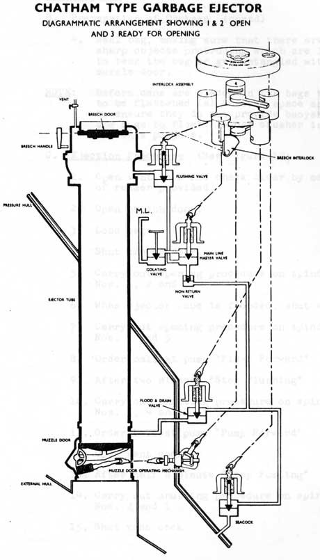
A. Description of Chatham Type Garbage Ejector
The ejector consists of a steel tube with a door at each end protruding through the pressure hull. It is connected to the main line for flushing and pumping. It is operated by a ratchet handle which fits on interlocks so no step in the procedure can be carried out until the previous step is complete and both doors cannot be opened together. In the same manner, whilst the breech door is open none of the flushing or hull valves can be opened.
The ejector is normally kept locked and permission has to be obtained before using, usually once per day as operational circumstances permit.
B. Preparation of Garbage
1. Place open bag in can.
2. Load bag with garbage
3. Add weight to bag until total weight of can and contents equals weight marked on can.
9-40
FIG 17
9-41
9.81 INTRODUCTION (CONTD)
B. Preparation of Garbage (contd)
4. Seal bag, making sure that there are no sharp objects protruding which are liable to tear the bag or get entangled with the muzzle door.
NOTE: Before cans are placed in the bags they are
to be flattened (a) to save space and (b) to ensure they do not provide buoyancy causing the bags to float. A can crusher is provided for this purpose.
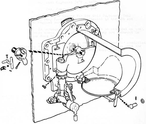
C. Ejection Procedure (See Figure 17)
1. Open vent cock end check clear by means of reamer provided.
2. Open breech door.
3. Load bags.
4. Shut breech door.
5. Carry out opening procedure on spindles Nos. 1, 2 and 3
6. When ejector cube is flooded, shut vent cock.
7. Carry out opening procedure on spindles Nos. 4 and 5
8. Order ballast pump "Flush Forward"
9. After two minutes "Stop Flushing"
10. Carry out shutting procedure on spindles Nos. 5, 4 and 3
11. Order ballast pump "Pump Forward"
12. Open vent cock
13. After half a minute "Stop Pumping"
14. Carry out shutting procedure on spindles Nos. 2 and 1
15. Shut vent cock
9-42
FIG 18
9-43
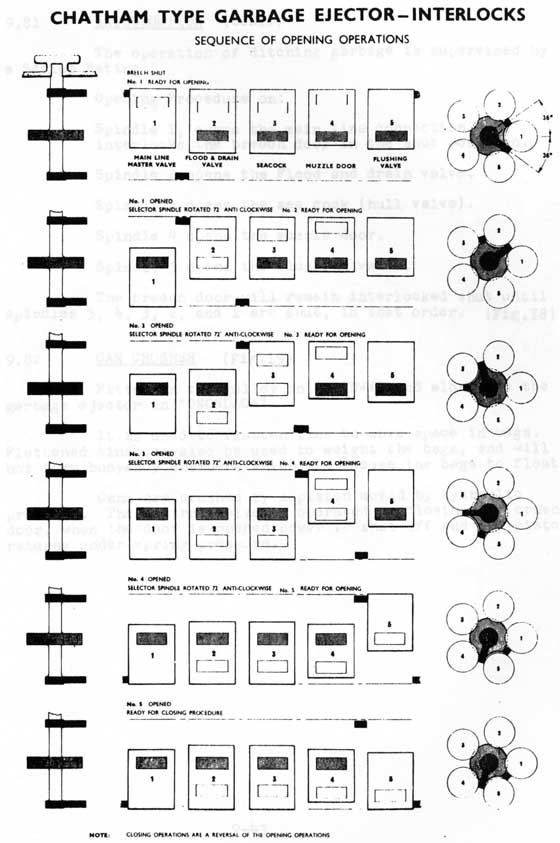
9.81 INTRODUCTION (CONTD)
The operation of ditching garbage is supervised by a Senior Rating.
Opening Procedure on:
Spindle 1, opens the main line connection, and interlocks the breech door in the shut position.
Spindle 2 opens the Flood and drain valve.
Spindle 3 opens the sea cock (hull valve). Spindle 4 opens the muzzle door.
Spindle 5 opens the flushing valve.
The breech door will remain interlocked shut until spindles 5, 4, 3, 2, and 1 are shut, in that order. (Fig.18)
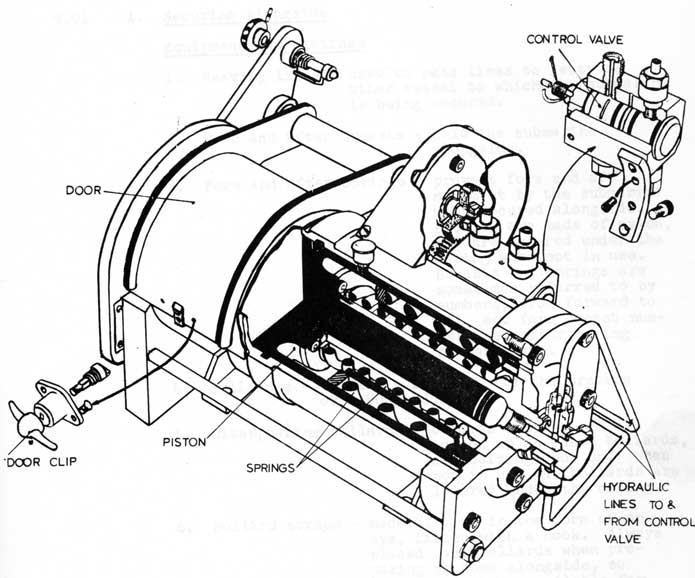
9.82 CAN CRUSHER (Fig.19)
Fitted in the galley on "OJIBWA" and alongside the garbage ejector in "ONONDAGA".
It is used to flatten tins to save space in bags. Flattened tins can also be used to weight the bags, and will not form buoyancy chambers which will cause the bags to float.
Cans are crushed by a piston moved by hydraulic pressure. The control valve is operated by closing the crusher door, when the door is opened power is shut off and the piston returns under spring pressure.
9-44
FIG 19 CAN CRUSHER (HYDRAULIC)
9-45
C.F. 'O' CLASS SUBMARINES
MISCELLANEOUS SYSTEMS AND EQUIPMENT
PART 9 - UPPER DECK GEAR
9.91 A. Securing Alongside Equipment and Fittings
1. Heaving lines - used to pass lines to jetty or other vessel to which the submarine is being secured.
2. Fore and after breasts - hold the submarine alongside.
3. Fore and after springs - prevent fore and aft movement by the submarine when secured alongside. Breasts are made of nylon, and are secured under the casing when not in use. Breasts and springs are sometimes referred to by numbers, from forward to aft, eg. fore breast number one, after spring number three.
4. Bullrings - provide a fairlead for the breasts over bow and stern.
5. Disappearing bollards - breasts and springs are turned up on these bollards, and seizings put on. When not in use the bollards are lowered under the casing.
6. Bollard straps - made of wire in the form of an eye, fitted with a hook. Always placed over bollards when preparing to come alongside, so that the hook is available for holding the lines of other submarines which may subsequently come alongside.
9-46
9.91 A. Securing Alongside Equipment and Fittings (contd)
7. Composite or hurricane hawser - made of 4 1/2" manilla with lengths of 3n wire at each end. Provides both strength and resiliency for use in heavy weather.
8. Gang plank- for access ashore. Made of aluminum, and must be fitted with guard rails when in position. It is securely clamped to the casing when proceeding to sea.
9. Capstan - a hydraulically operated warping barrel used for heaving in the fore breast when coming alongside.
Procedure - The bow of the submarine is brought close enough to the jetty to pass a heaving line. The fore 'breast is then passed and secured ashore, and brought to the warping barrel. Using the twisting effect of the screws the stern of the submarine is brought in to the jetty. Springs and after breast are passed, care being taken to keep lines clear of the water so as not to foul the screws. All lines are hauled taut and secured to bollards, and doubled up.
B. Anchor and Cable Work Equipment and Fittings
1. Anchor - 'Byres' stockless type, weight 16 cut. Fitted with flukes to grip the sea-bed.
2. Cable - connects anchor to the submarine. Length of cable is measured in shackles of 15 fathoms (90 feet) each. Normally five shackles are carried.
3. Cable Locker - a free flood compartment in No. 1 M.B.T. to hold the cable. The inboard end of the cable is secured to a cable link which is attached to the submarine.
9-47
9.91 B. Anchor and Cable Work Equipment and Fittings (contd)
4. Anchor Door - provided for streamlining purposes. It is always shut unless the anchor is ready for letting go. Held shut by a pin. Both the in and the opening and shutting of the door itself are controlled from the casing by rod gearing.
5. Bottle screw slip - fitted to hold the anchor right home when it is stowed.
6. Blake slip - provides a quick method of letting go the anchor.
7. Windlass or cable holder - a drum to take the links of the cable. It is operated by a hydraulic motor, and heaves in or veers cable as required. It is fitted with a clutch to disengage it from the motor and with a brake. The clutch and brake, and the motor controls, are operated from the casing by rod gearing.
8. Compressor - operated like a guillotine to grip and secure the cable.
ANCHOR & CABLE EQUIPMENT
9-48
9.91 B. Anchor and Cable Work Equipment and Fittings (contd)
9. Pushing up rope - a wire or nylon rope fitted with a spring hook at one end and an eye at the other. Used when coming to a buoy.
10. Ship-to-buoy shackle - a special shackle which can be secured to the cable and to the ring of a buoy.
Procedures
1. Anchoring - The pin is withdrawn from the anchor door, and the door opened. The windlass is clutched to the motor, and the bottle screw slip knocked off. The anchor is then veered a short distance under power until its weight is taken by the Blake slip; when the windlass is unclutched. The anchor is thus held by the Blake slip alone. At the order "slip" the Blake slip is knocked off, and the anchor and cable run out under their own weight. The brake is used to control the laying out of the cable along the bottom. The submarine rides with the weight shared between the brake and the compressor, with the Blake slip on slack as a preventer.
2. Weighting - The windlass is clutched to the motor and the compressor, brake and Blake slip taken off. The motor drives the windlass, thus heaving in the cable. When the anchor is close home the bottle screw slip is put on and screwed up tight. The compressor, brake and Blake slip are put on, the slips being lashed to prevent rattles, and the anchor door shut and pinned.
3. Coming to a buoy - The cable is broken just inboard of the bottle screw slip, which is left holding the anchor and a short length of cable. The free end of the cable is led out through a hole in the side of the casing, ship-to-buoy shackle secured to the end of the cable. At the same time the picking-up rope is flaked out ready on the casing. The buoy jumper fully inflates his life belt, and a line is secured to his waist. The bows of the submarine are placed close alongside the buoy, and the buoy jumper leaps onto the buoy, the line around his waist
9-49
9.91 B. Anchor and Cable Work Procedures (contd)
3. (contd)
being tended on the casing. The spring hook end of the picking up rope is passed down, the buoy jumper hooks it to the ring of the buoy and climbs back aboard. The picking up rope is brought to the capstan, and heaved in until the buoy is securely held alongside the submarine. The buoy jumper then jumps back onto the buoy and secures the cable to the ring of the buoy by means of the ship-to-buoy shackle. The picking up rope is rigged as a slip rope, to enable the submarine to slip from the buoy when desired.
C. Towing
Arrangements are made to enable a submarine to be taken in tow if necessary, the fittings being so designed that personnel do not have to go on the casing in order to pass the tow.
1. Main Towing
The anchor is 'catted' and its cable disconnected, the latter being passed over roller fair leads through the forward mooring pipes (port or starboard), and adaptor piece being fitted to the outboard end of the cable.
2. Emergency Towing
The towing pennant is made of 3 1/2ì wire, with a length of chain fitted at the inboard end. The inboard end is secured to the submarine by a towing slip which can be released from the F.T.R. The chain is stowed in a recess on top of the fore casing. The recess being packed with a bitumastic composition to prevent rattles. The wire is led from forward to aft along the side of the casing, held in place by metal clips, and then up the side of the fin to the bridge.
3. Eyes and Sheaves
A system of fixed eyes and removable sheaves is provided so that a line may be led vertically downward from the bridge to the control room and thence aft to the generator room.
9-50
9.91 C. Towing
Procedure - A light line is passed from the towing ship, and using the sheaves is led down into the control room and aft. This line is manned, and successively heavier lines hauled across from the towing ship until the eye of the towing wire comes to hand on the bridge. The towing wire is shackled to the free end of the submarine's towing pennant. As the towing ship takes the strain the towing pennant is pulled away from the fin and casing.
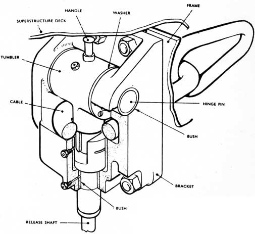
The towing slip fitted in the forward
casing is of conventional tumbler and horseshoe type and is hand-operated from inside the FT R. It is tested to a direct pull of 60 tons. A handle accessible from the top of the casing, is fitted for turning the tumbler clear of the horseshoe when connecting the towing cable. Release shafting passes through a hull gland, its various lengths being joined by universal couplings.
Towing Slip
9-51
9.91 C. Towing
4. Local Towing
A suitable length of towing lead is stowed in the superstructure for local towing. A soft eye at the outboard end is passed along the top of the superstructure to a fair lead and down through the hinge cover opening above the windlass and then led underneath the superstructure by means of roller fairleads and out through the mooring pipe on the port or starboard sides. The soft eye at the outboard end of the towing pendant is attached to the towing vessel, whilst the inboard end is attached to the forward disappearing bollards.
9-52
C.F. 'O' CLASS SUBMARINES
MISCELLANEOUS SYSTEMS AND EQUIPMENT
PART 10 - NOISE REDUCTION
9.101 REASONS FOR NOISE REDUCTION
Before the Second World War (1939-1945) the sound made by submarines was used to detect them by listening (hydrophones) and by echo devices such as Asdic. Self made noise also interferes with the operation of the submarine sonar sets.
The use by the enemy of acoustic underwater weapons called for effective countermeasures so that the silencing of submarines both when lying on the bottom and when moving at slow speed was taken in hand.
Airborne noise is not so important operationally as waterborne noise, but nevertheless it is receiving attention.
9.102 SOURCES OF NOISE
Systematic noise surveys of a number of ships showed that noises originate from five main sources:
(a) Man made - hammering, slamming of doors, etc.
(b) Water - casing holes and projections, hull valve openings
(c) Propeller - cavitation, 'singing', vibration
(d) Rattles - casing flaps, pipes, loose gear
(e) Machinery
The vibration of these radiate noise into the water, and provide a target for the enemy's detection apparatus and his acoustic weapons, and limits the range of our own ship's apparatus.
9-53
9.103 METHODS OF NOISE REDUCTION
The reduction of man made noise is of concern to
every member of the ship's company. Ship's Standing Orders
clearly lay down "Quiet States" and every man should be familiar with these and become noise conscious.
Water noises can be reduced by streamlining - bridge fin, fairing plates, bow shutters.
Propellors cavitation has been reduced by design, the onset of cavitation non occurring at higher speeds.
Fairing of the blade tips to reduce 'singing' and maintaining 'A' Bracket and stern tube bush clearances within the designed limits will reduce vibration.
Careful attention to securing pipes, loose gear and casing flaps and equipment before proceeding to sea ensures that rattles are not forthcoming when at sea.
All machinery is mounted on resilient mounts known as Vibration Mountings which isolate the machine from the structure to which it is attached.
9.104 MACHINERY MOUNTINGS
A. Shock Mountings are those which give shock protection to machinery and equipment against external forces such as depth charging. They are not intended to give vibration (noise) insulation. Types A, B, C, D, E, F, G and GX.
B. Vibration Mountings are those which reduce vibration transmitted to or from machinery and equipment over specified frequency ranges. They are not specifically designed to give protection against shock and are not generally used in submarines.
C. Shock/Vibration Mountings are those which give protection against shock and also noise insulation. Types L, M. MMK2, P, PD, S and W.
9.105 DEFINITION OF CHARACTERISTICS
A. The accelerating portion is that portion which resists the upward shock forces in surface ships and radially inward forces in submarines.
9-54
9.105 DEFINITION OF CHARACTERISTICS (CONTD)
B. The DECELERATING portion is that portion which resists the downward shock forces in surface ships and the radially outward forces in submarines.
C. The NOMINAL LOAD is the load for which the mounting is designed. The STATIC or NOMINAL DEFLECTION is the deflection under the nominal load.
D. The SHOCK DEFLECTION is the approximate instantaneous deflection of the mounting under a severe shock.
E. The NATURAL FREQUENCY is the frequency of vibration when under nominal load.
Mountings are designated by a type letter, eg. Type A, B, C, etc. A double letter is used to indicate an arrangement in which the decelerating unit is below the seating on which the unit stands.
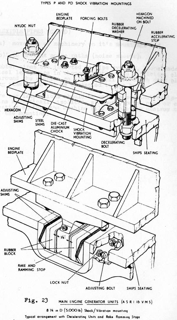
Some mountings are designed with separate accelerating and decelerating units and full shock protection is only maintained if these are fitted.
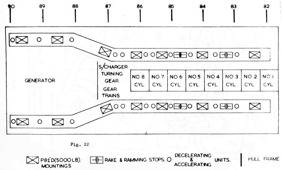
The diesel generating sets are mounted on 14 shock/ vibration mountings (Type P8 1/4 - D) , the 22 accelerating and decelerating units are separate and are positioned as shown in figure 20.
Four Rake and Ramming stops are fitted to restrict the fore and aft float of the set to 1/8". See Figure 21. More mounting details are given in BR 3011 and BR 3012. (Fig. 21)
Mountings should be kept clean and free from oil and grease, They are not to be painted but must be coated with NECOL Lacquer which is light blue in colour and must be maintained in good condition.
9.106 FLEXIBLE PIPES
To further isolate machinery from the ships structure, it is necessary to provide pipe systems, electrical lead, shafts etc, which join the machine to adjacent equipment or the hull with sufficient flexibility to accept:
9-55
ARRANGEMENT OF ASRI S&S MOUNTINGS & RAKE & RAMMING STOPS
9-56
9-57
9.106 FLEXIBLE PIPES (CONTD)
(a) movement of machinery on it's mountings and
(b) to prevent noise paths (noise shorts)
Rubber pipes are inserted in pipe systems, loops made in electrical lead, gaps in channel plates, and sufficient clearance all around the machine so that it will not touch deck plates or anything else which may be connected to the hull.
Pre sea inspections should be made to see that equipment remains acoustically isolated, spanners, paint cans or even buckets resting against the machine will completely destroy the purpose of the mounting.