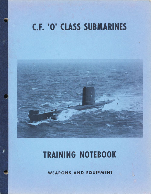
C.F. 'O' Class Submarines - Weapons and Equipment, describes the weapons and associated systems of the Oberon class submarines.
In this online version of the manual we have attempted to keep the flavor of the original layout while taking advantage of the Web's universal accessibility. Different browsers and fonts will cause the text to move, but the text will remain roughly where it is in the original manual. In addition to errors we have attempted to preserve from the original, this text was captured by a combination of optical character recognition and human typist. Each method creates errors that are compounded while encoding for the Web. Please report any typos, or particularly annoying layout issues with the Mail Feedback Form for correction.
The O class submarine is equipped with eight torpedo tubes by means of which a variety of weapons can be discharged. The six tubes mounted in the bow can be used to fire a wide range of offensive and defensive weapons while the two in the stern are designed primarily for countermeasure torpedoes.
The forward torpedo stowage compartment has been built to allow a generous number of reloads to be carried. For these to be handled as efficiently as possible in the space available hydraulic powered equipment has been provided to assist in loading and handling of the weapons.
Two methods of discharge are fitted: air impulse or electric start, and these can be initiated locally or remotely as required.
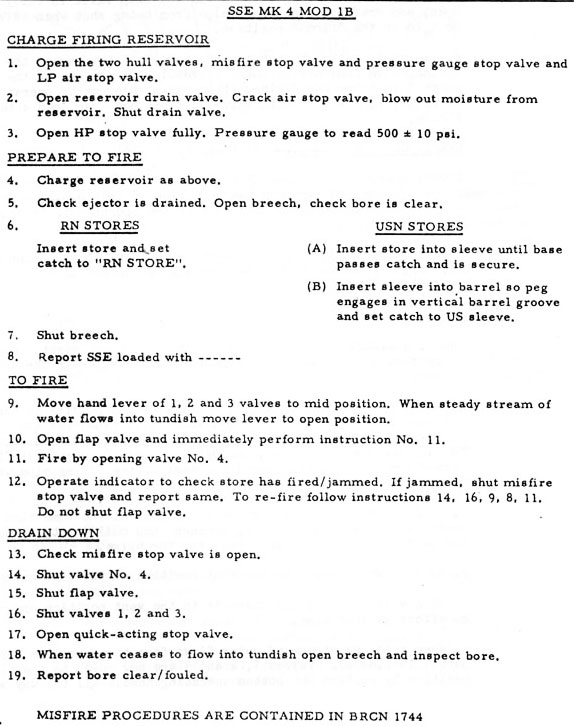
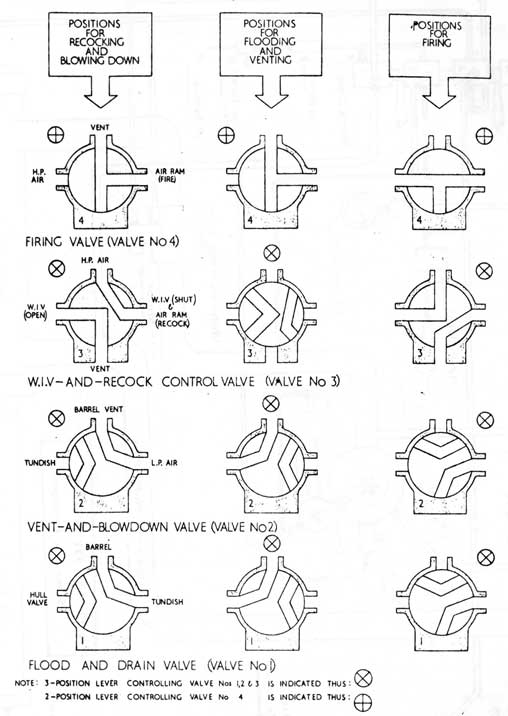
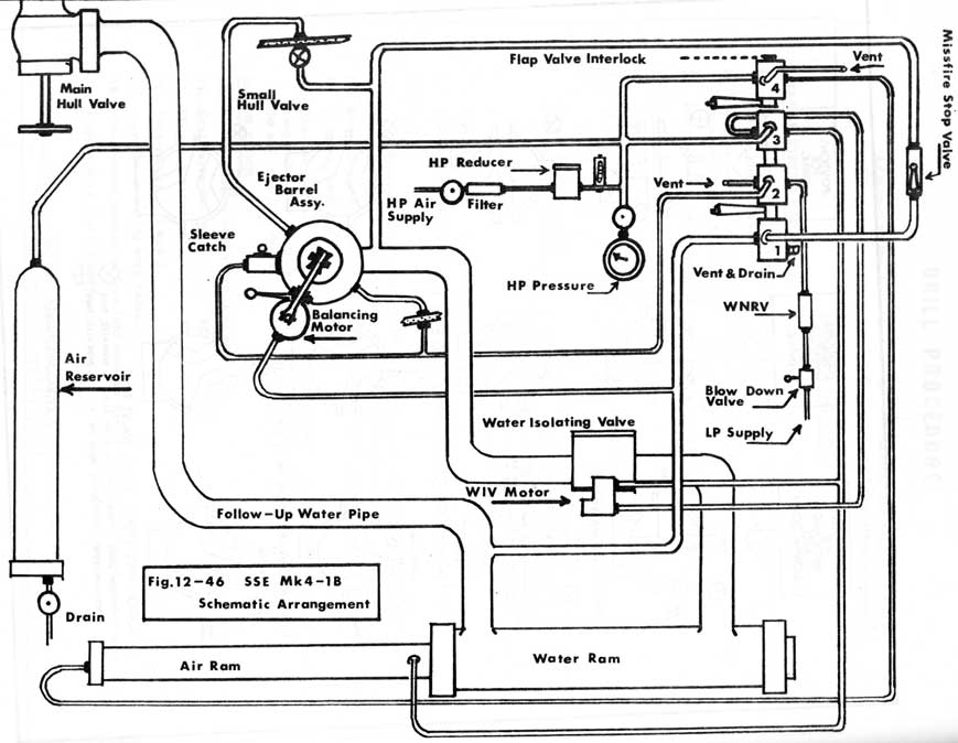
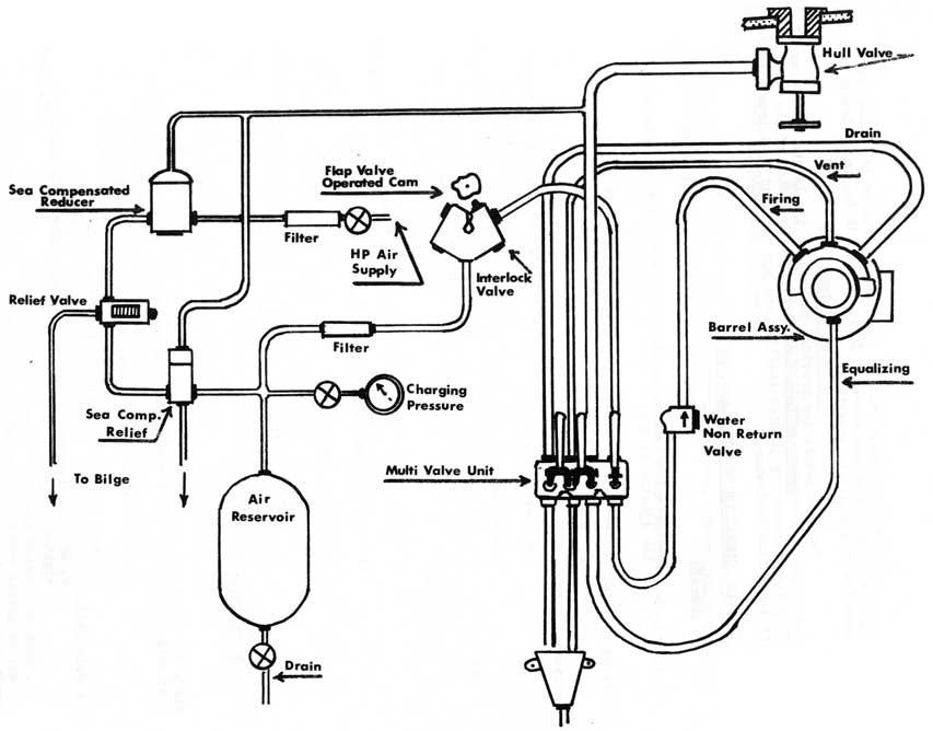
Two submerged signal ejectors, located forward and aft, are provided for releasing markers and flares for exercise and. emergency purposes and the one aft can also eject decoys and other special stores.
This chapter is provided to give the submarine trainee a thorough understanding of the weapons carried and how they are discharged from the submarine.
The terminology used in Part 12 conforms to the publications, handbooks and drawings supplied to the submarines.
12-3
12-1-02 FORWARD TORPEDO TUBES
The six forward tubes are the "wet slack fit" type and can be flooded, equalized and operated down to full diving depth. Each tube consists of two rolled and welded lengths bolted together at the domed bulkhead with a bowcap at the forward end and a rear door at the after end. The two openings are interlocked to prevent them from being opened at the same time. Attached to the bowcap is a shutter that seals the rectangular opening in the bow for streamlining and opens with the bowcap to allow a torpedo to be fired.
12-1-03 TORPEDO TUBE CONSTRUCTION
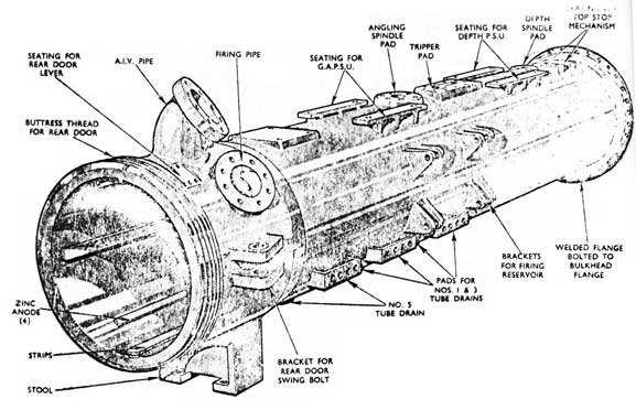
1/ INBOARD LENGTH - (FIG 12-1)
This is of 0.50 in. thick steel plate rolled and welded to form a tube of 22.5 in. internal diameter. It has a connecting flange welded to its forward end and a forged rear-end welded to its after end. The continuous tube is about 116 in. long. The rear-end forging is of greater thickness than the tube and it carries firing and venting pipe flanges, rear door locking bolt and hinge brackets and in addition, a two start buttress thread is machined on its after end to take the rear door locking ring. The after edge forms a joint face for the rear door.
The connecting flange is machined from solid steel. It consists of a heavy flange with a short projecting collar which is welded to the outer end of the inboard length. Both the rear-end and connecting flange sections have the same internal diameter as the tube section.
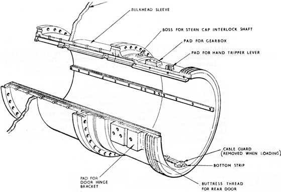
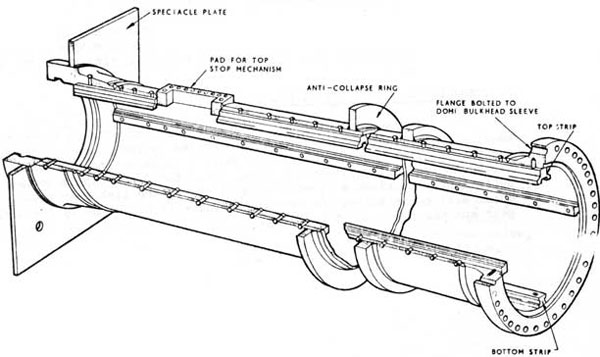
2/ OUTBOARD LENGTH-(FIG 12-2)
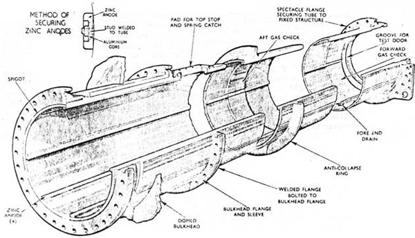
This is also of three sections, namely the tube, flange and sleeve aft and lip end forward. When welded together they form a tube about 175 in. long. The tube portion is rolled and welded to the same dimensions as the inboard length, but is longer. The sleeve portion passes
through the domed bulkhead and, to provide additional strength this
point is of 1 1/8 in. solid drawn steel tube. At the forward end of the
sleeve is a 1 1/4 in. thick flange which, when the tube is erected in the
submarine is bolted to the flange of the bulkhead sleeve. The lip end is a short length of solid-drawn steel tube. It is secured to the forward bulkhead with the bolts which pass through a flange welded to it, about 6 in. from the forward end. A 1 in. thick flange is welded around the middle of the outboard length; this provides additional strength to the unsupported part of the tube passing through No. 1 main ballast tank.
12-4
Fig 12-1 Inboard Length
Fig 12-2 Outboard Length
12-5
3 BEARERS
To form bearers for weapons, aluminum-bronze strips are fitted at the top, bottom and both sides of the tube bore. They are riveted to the to tube and extend from the rear end to within 5 in. of the lip end. The top strip is wider and slotted down the centre to provide a channel for the top lugs of weapons.
4 GAS CHECK RINGS
Two of these are fitted in the outboard length, one is in line with the forward end of the bearer strips and the other about 6 in. further' aft. Each ring is of gunmetal and is shaped to fit between the bearers. The bearer strips and check rings are machined to an internal diameter of 21.1 in.
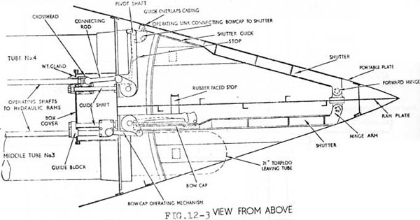
5 BOW CAPS-(FIG 12-3)
This is a circular steel door with a dexine sealing ring held in a groove.. in its inner face by a retaining ring and set bolts. The sealing ring bears against the lip-end when the bow-cap is shut.
At the top of the hinge shaft is a flange to which is bolted a top plate. This top plate is fitted to accept the connecting rod whit is in turn attached to a crosshead and operating shaft. Fore and aft movement of the operating shaft acting through the crosshead and connecting rod is converted to angular movement of the bowcap by the top plate. i.e. causes the bowcap to open and shut.
12-6
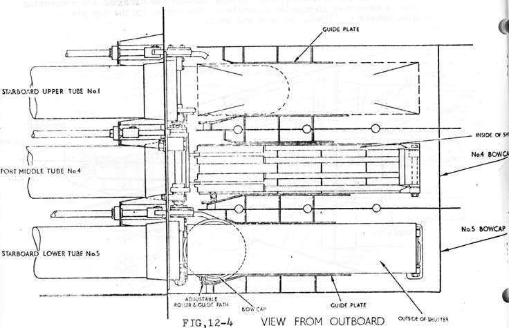
6 BOW SHUTTER-(FIG 12-4)
Each tube opening in the casing is sealed by a rectangular steel plate to streamline the bow. This plate, or shutter, is hinged at the for ward end and supported by rollers at the after end. The rollers run on an arced gunmetal strip secured to the bottom plating in the shutter space. Two slotted guides are fitted, top and bottom, to the back face of each shutter. The shutter is connected to the outboard face of the bowcap by swing links which operate in the slotted shutter guides.
When the bowcap is being opened the swing links, operating in the shutter guides, draw the shutter inwards effectually covering the inside face of the bowcap when it is fully open. The smooth outer face of the shutter now acts as a guide plate for a weapon leaving the tube and protects the bow cap sealing ring from being damaged.
12-7
7 HYDRAULIC RAMS-(FIG 12-5)
Hydraulic rams for operating the bowcaps are mounted in the compartment, parallel with the inboard side of each tube and bolted to pads on the inner face of the domed bulkhead. Each ram is double-acting and powered by the main hydraulic system. Should the main hydraulic system fail the rams can be supplied by a hand pump in the FTR.
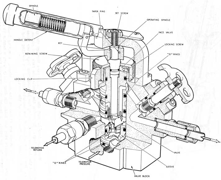
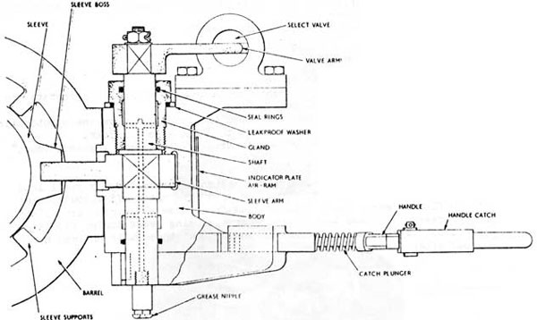
8 BOW CAP OPERATING GEAR CONTROL VALVES-(FIG 12-6)
To operate each hydraulic ram a control valve assembly is bolted to a pad near the rear end of each tube. Each assembly consists of a steel block containing a rotary faced valve operated by a hand lever. The hand lever also operates a locking bolt connected to the rear door locking ring. Each valve is fitted with two double faced isolating valves and an operating lever indicator plate.
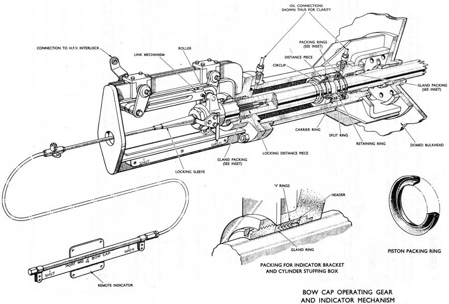
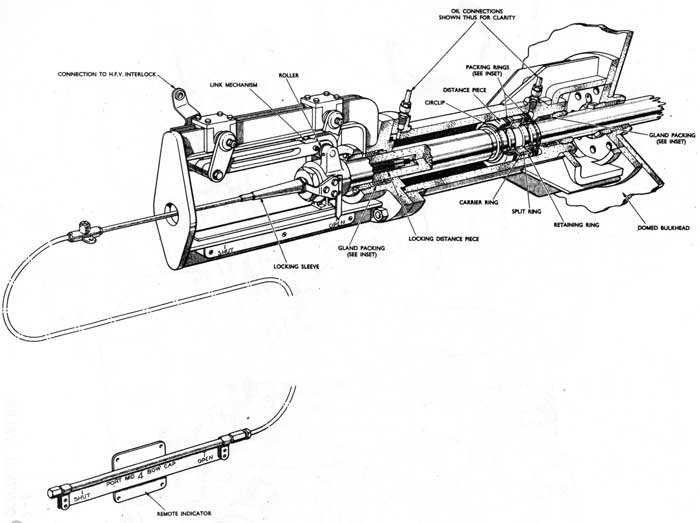
9 BOW CAP INDICATORS.-(FIG 12-7)
An indicator pointer is bolted to the inboard end of each bowcap operating shaft. An indicator plate is bolted to each ram housing and has the OPEN and SHUT positions clearly marked on its surface. The operating shaft pointers are aligned with the indicator plates to give a positive open/shut indication.
As the operating shaft pointer is not easy to sight, a remote indicator is fitted near the rear end of each tube. These indicators are operated by a cable and tube system attached to the inboard end of each operating shaft. The cable operates a pointer which slides along a rectangular plate marked with the tube number and the "open" and "shut" positions. Although the remote indicator is convenient, the operating shaft pointer should always be considered as the only reliable indicator.
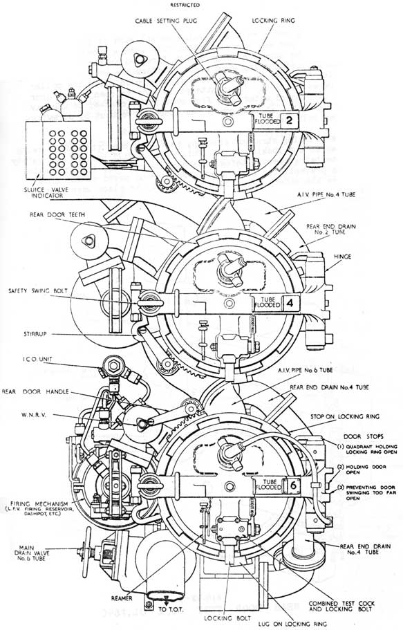
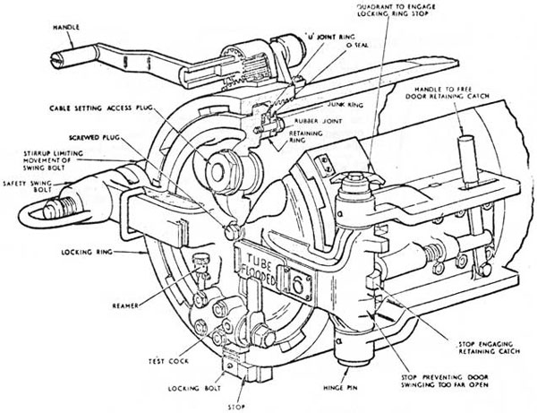
10 REAR DOORS-(FIG 12-8)
A circular dish shaped cast-steel door with a neoprene "U" seal, seals the inboard end of the tube. The door is hinged at its inboard edge and has a cast projection at its outboard edge machined to accept a safety swing bolt and is fitted with a handle. On the door rim are ten equally spaced rectangular lugs.
A locking ring is screwed on the two-start buttress thread on the rear end of the tube. This locking ring has ten equally spaced rectangular lugs machined into its inner face. The locking ring is rotated by a rack and pinion operated by a handle.
12-8
Fig 12-5
Bowcap Operating Gear
12-9
FIG. 12-6
BOWCAP OPERATING CONTROL VALVE
12-10
FIG. 12-7
BOW CAP INDICATORS
10 continued...)
When the door is shut the door lugs pass through the gaps between the locking ring lugs. By moving the handle the rack and pinion gear rotates the locking ring forcing the locking ring lugs over those of the door. Due to the action of the buttress thread the locking ring forces the door hard against the rear face of the tube.
Three stops are fitted on the door hinge. A spring loaded catch engages the centre stop and holds the door fully open; a handle is fitted for withdrawing the catch. A second stop prevents the door from swinging too far open. The remaining stop engages a lug on the locking ring when the door is open and prevents the locking ring from being turned until the door is shut.
12-11
Fig 12-8
Rear Ends General Arrangement
12-12
The safety swing bolt is pivoted on the side of the tube opposite the hinge, and has a collar which fits into a recessed slot in the lug formed on the door. A large nut is threaded on the end of the bolt, and bears against the lug when tight. Before the bolt can be swung clear of the lug the door must be opened slightly to allow the collar to clear the recessed slot. If an attempt is Made to open a rear door when the tube is flooded water will flow when it is cracked to withdraw the safety swing bolt. In this event the door can be shut by screwing-up the locking bolt nut.
A restraining strap or stirrup, is fitted over the safety swing bolt and welded to the locking ring. This stirrup will prevent the safety swing bolt from being removed before the door is released by the locking ring. It also prevents the locking ring from being moved to the shut position before the safety swing bolt is properly in place when shutting the door.
FIG. 12-9
REAR DOOR TEST COCK UL. 16405
12-13
10 Continued...)
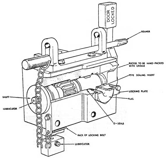
A combined test cock and locking bolt is fitted oh the bottom centre of the door. Its two functions are:
A. To secure the locking ring when the door is shut;
B. To provide a means of determining whether the tube is flooded or dry.
When it is in the locked position the locking bolt bears against a lug on the locking ring and prevents it from being turned.
When the handle is being moved to the unlocked position it opens a port into the tube before the locking bolt is withdrawn.
At this point the reamer provided is to be used to prove the test port clear. Once this has been done and no water flows, the handle can be moved to the UNLOCKED position; the test port however is still open. The locking ring is now free to rotate.
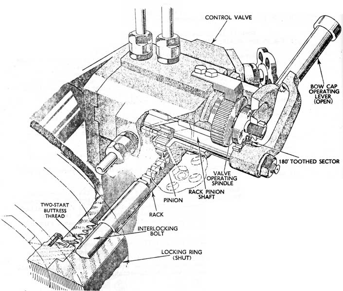
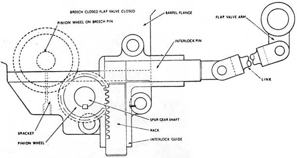
12-1-04 REAR DOOR AND BOW CAP OPERATING LEVER INTERLOCK-(FIG 12-10)
The bow cap operating lever is interlocked with the tube rear door, so that:
A. The operating lever cannot be moved to OPEN unless the rear door is fully shut;
Pt. The rear door locking ring cannot be moved unless the operating lever is at SHUT.
The control valve and assembly is mounted on the inboard side of the tube. The bow cap operating lever, which moves through 90 degrees has a 180 degree toothed sector on its boss; this engages with a similar toothed sector on the control valve operating spindle. The lever is keyed to one end of a pinion shaft, the other end of which has a pinion engaging with the rack of an interlocking bolt.
When the locking ring is fully shut and bowcap operating lever moves to OPEN the bolt slides into a hole in the rear door locking ring and prevents the ring from being moved. If the locking ring is not fully shut the bolt will not be aligned with the hole, making it impossible to move the operating lever in the OPEN direction.
NOTE
This interlock is not directly connected to the bowcaps. In the event of a hydraulic failure the bow cap could be open with the operating lever in the shut position. Correct operation of the test and
12-14
locking cock and safety swing bolt will give ample warning in this event and will insure that watertight integrity is maintained.
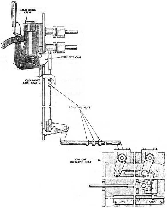
Fig 12-10
Bowcap Operating Lever and Rear Door Interlock
The end cover of each bow cap ram cylinder has a framework welded to it. The frame work supports a link mechanism which operates an interlock between the ram and the hand-firing valve.
When the ram moves from SHUT to OPEN, the link mechanism roller moves along the straight length of cam bar until the bow cap has opened sufficiently for a weapon to leave the tube without fouling the bow cap and shutter (the JUST FIRE position). The roller then contacts the hook which moves the cam bar and rod linkage. The rod linkage will move the interlock-cam clear of the toe of the hand-firing valve allowing the valve to be moved into the FIRE position.
When the bow cap is being shut the first movement of the link mechanism will move the interlock cam back into the SAFE position preventing the hand-firing valve from being moved.
NOTE
Always replace the HFV before shutting the bow cap or the interlock will be damaged.
12-1-06 DRILL FOR OPENING A REAR DOOR AND SAFETY FEATURE SUMMARY (FIG 12-12)
1. Always obtain permission before attempting to open a rear door. IAM Ships Standing Orders).
2. Check the appropriate bow cap control valve in the shut position. This also ensures that the control valve operated locking bolt is withdrawn from the locking ring.
3. Check that both bow cap indicators are in the shut position.
4. Crack the individual tube vent on the nine valve chest to relieve any air pressure in the tube, then shut it.
5. Remove the reamer from its brackets thereby freeing the test and locking cock handle.
6. Move the handle to the mid-position, insert the reamer into the test port and prove it clear, then remove the reamer and observe that water is not present. Then move the handle to the UNLOCKED position.
12-17
Fig 12-12
Typical Rear Door
7. Rotate the locking ring until the stirrup comes in contact with the safety swing bolt.
8. Slacken the safety swing bolt end nut and break the door seal.
9. If no water is present continue unscrewing the end nut until the collar is free, then swing the swing bolt clear of the bracket.
10. Open the rear door completely ensuring that it is firmly held by the spring catch.
12-18
12-1-07 FLOODING DRAINING, VENTING AND BLOWING-
1 REQUIREMENTS
For the correct working and firing of the torpedo tubes it is necessary to be able to
a. Flood the tubes from a tank inside the submarine so that no more water can enter the tubes when the bow caps are opened for firing, this maintaining the longitudinal trim of the submarine.
b. Drain the tubes into a tank inside the submarine after firing so that trim is maintained; and the rear doors can be opened.
c. To allow air to leave or enter the tubes while they are being flooded or drained.
d. Use low pressure air for flooding up and to assist draining down.
e. Allow the tubes to be equalized to permit opening the bow caps & to allow gases generated by a hot-run to be vented overboard.
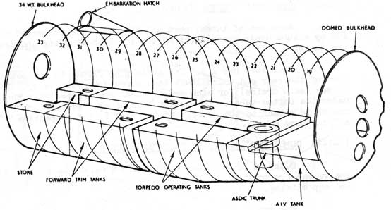
12-1-08 TANKS-(FIG 12-13)
Three internal tanks are provided for operating the forward
tubes:
1. The AIV tank (Automatic inboard vent, )which is an open-topped tank of 1,875 gal. capacity. It is immediately below the rear ends of the tubes.
2. Two T.O.T. tanks (Torpedo operating) situated aft of the AIV, port and starboard and divided by the trench, each holding
approximately 2,400 gals. These two tanks are entirely separate.
12-19
Fig 12-13
FIG. 12-14
TUBE DRAIN SYSTEM
12-20
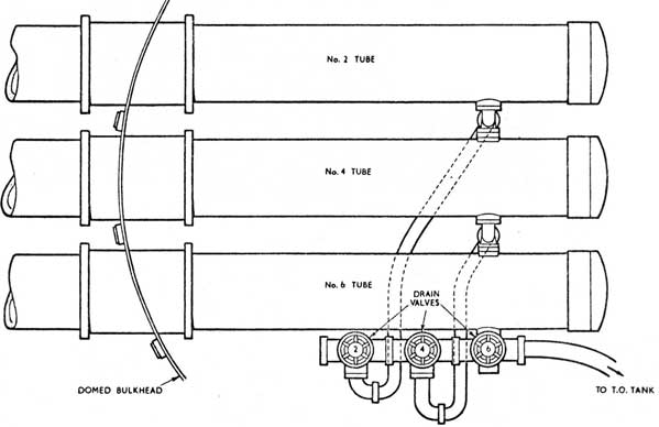
12-1-09 TUBE DRAIN SYSTEM (FIG 12-14)
Each set of tubes, port and starboard, is connected to its TOT by a tube drain system that serves tor both flooding and draining the tubes.
Each tube has a 3.5 in. drain pipe fitted to the bottom centre line of the rear end which leads to a screw down stop valve . The stop valves (main drains) for each set of tubes are grouped near the deck under the bottom tubes. The outlet side of each set of three in drains is common to the group, and is piped to the respective TOT by a 7 in. bore: pipe.
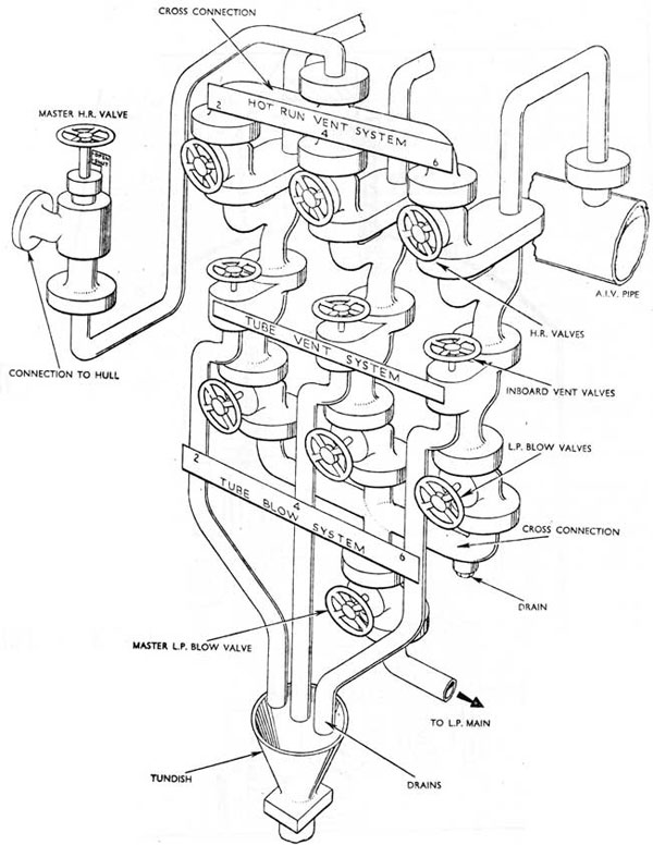
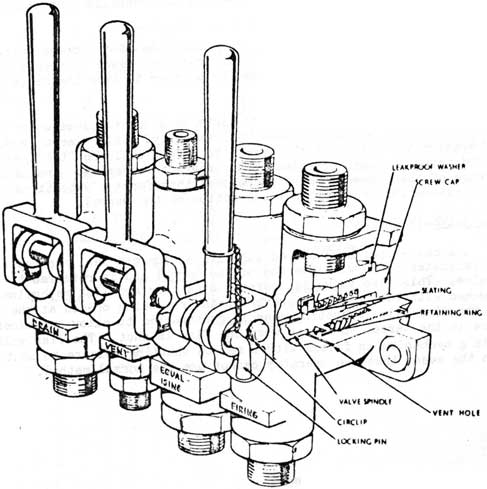
12-1-10 COMBINED HOT-RUN, VENT AND BLOW SYSTEM-(FIG 12-15)
Outboard of each set of tubes is a valve chest consisting of the valves for venting, blowing down and venting hot run gases overboard and equalizing.
The group of valves is designed to allow any one tube or all three tubes in a set to be operated individually or collectively.
Each valve chest has three rows of three screw down stop valves, which, from top to bottom, are the hot run (equalizing), tube vent and tube blow valves respectively.
The outlets of the hot run valves are interconnected by a cross connection pipe, which in turn is connected to a master hot-run hull valve. The blow valves are similarly connected and are joined to a low-pressure blow by a master valve at the bottom of the panel. The design of the castings that connect the hot run valves to the tube blow valves, and of the valve bodies, provides a seperate continuous channel with the two branches between each pair of valves. Each top branch is piped to the AIV pipe of its tube, and each bottom branch forms the body of its tube, vent valve. The outlets of the three vent valves are piped to a tundish which drains into the AIV tank. All the pipes and casting channels of the system are 2.5 in. bore with a drain plug screwed into the lowest part of the blow valve interconnection pipe.
12-21
Fig. 12-15
Hot Run, Vent and Blow System
12-22
Fig. 12-16 Typical Wet Slack-Fit Torpedo Tube
12-23
12-1-11 OPERATION-(FIG 12-16)
The two systems, Drain, and Vent Blow, enable the tubes to be flooded, drained, and when speed is essential, to be blown down. In addition they provide for venting overboard and equalizing. Any one of these operations can be performed on all three tubes at once if necessary.
For flooding a tube, the tube vent and main drain are opened. The TOT combined vent and blow valve is put to Blow. Low pressure air is introduced into the TOT which will push water up the 7in drain pipe, through the main drain and into the tube. The air in the tube is forced, out the vent. When the tube is full water will flow from the vent.
For draining the tube, the TOT combined vent and blow valve is put to vent, the tube vent is opened and the main drain is opened. The water will drain out of the tube by gravity. To blow down the tube the TOT is put to vent, the main drain and blow down valve are opened. Low pressure air is supplied to the tube through the master blow down valve and this air pressure will force the water out of the tube and into the TOT, the air pressure being maintained until the tube is empty.
12-1-12 MAIN DRAIN GRATINGS
To prevent debris from entering the drain systems, gratings are fitted on the bottom of the tubes over the drain pipe orifices.
Canadian "O" class submarine bow tubes are fitted to discharge MK 37 wire guided torpedoes. The primary dispenser containing the required communication wire is fitted in the torpedo. A smaller dispenser for dispensing communication wire to account for the movement of the submarine during a torpedo run is fitted in the rear end of the torpedo tube. This dispenser is fitted to a portable base plate which locks in place on the rear end of the bottom guide strip.
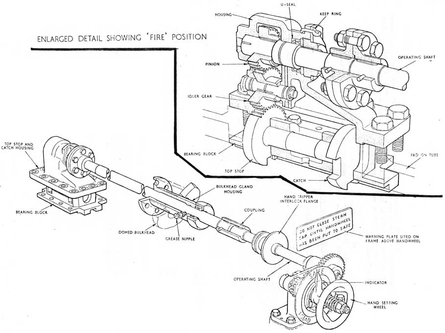
The top stop and spring catch bear against the forward and after ends respectively of the top lug of a loaded weapon; they prevent the weapon from moving forward and aft. The spring catch is lifted
automatically by the top lug when a weapon is being loaded, but it must be lifted by hand before the weapon can be withdrawn from the tube. The top stop is lifted automatically by an air motor during a firing cycle, so that the weapon is free to leave the tube. They are contained in a watertight stop box which is in No. 1 main ballast tank and is spigoted and secured to a pad on the top centre line of the tube. A slot in the spigot is aligned with the tube top bearer strip groove, and the stop and catch normally project in to the slot. Their operating mechanism is contained in an operating box secured to a pad on the top of the tube, just abaft the dome bulkhead. They are connected to their operating box by one operating shaft each; the top stop shaft passing through the centre of the spring catch shaft. Thus, one dome bulkhead gland suffices for both shafts.
The top stop is a 1.5 in. diameter stainless-steel bolt and is fitted in the foremost of two housings in the stop box. The spring catch is a 1 in. diameter stainless-steel bolt and is fitted in the after housing of the stop box. It is loaded by a spring to keep it IN. The spring is attached at one end to a lever clamped to the operating shaft, and at the other to a bracket secured to the tube.
A plate cover is secured to the operating box and has a slot to guide the clutch handle into either engaged or disengaged positions of the clutch. The handle can thus be used for lifting tie top stop or spring catch, or for shaking them up occasionally. For indicating whether the top stop and spring catch are IN or OUT, an indicator plate is secured by screws to the cover and aligns with the indicator pointers.
The mechanism for operating the top stop is contained in a cylindrical hollow housing on the underside of the operating box. The housing has an air motor cylinder at one end.
The motor cylinder has two air pipe connections; one from a hand firing valve (H.F.V.), and one from an auxiliary small firing valve (aux. S.F.V.) motor. An exhaust groove in the piston is aligned with the latter air connection, and, when the top stop is DOWN, it connects the aux. S.F.V. motor bore to atmosphere, via a vent plug in the housing.
12-26
FIG.12-19 TOP STOP AND SPRING CATCH ARRANGEMENT
12-27
Thus, the top stop is:
a. Normally held IN by the sleeve spring force acting through the sleeve, quadrant, top stop operating shaft and pinion.
b. Lifted to OUT when, during a firing cycle, air is supplied to its motor cylinder from the H.F.V.; the piston exhaust groove being sealed by the housing, and the air passing to the aux. S.F.V. motor.
c. Returned to IN when the H.F.V. is replaced after firing; the sleeve spring forcing the piston back to its normal position, thus uncovering the exhaust groove and venting the aux. S.F.V. motor to atmosphere; the outer end of the top stop operating cylinder being vented via the H.F.V.
2 TUBE DISCONNECT SWITCH-(FIG 12-20)
When a tube is loaded with a torpedo it must be connected to a torpedo control system within the submarine., To do this, an umbilical cable attached to the torpedo is plugged into a fitting in the tube rear door, which is connected by an external cable to a disconnect switch on the tube; the switch being permanently wired to control system circuits. On firing, the circuits are broken by the automatic operation of the switch. An operating arm on the switch is so connected by levers to the top stop shaft that when the tube firing lever is pulled, the top stop operating gear triggers the switch. The levers are so arranged that the switch operates before the top stop is fully raised.
The switch gear is contained in split aluminum-alloy casing. One part of the casing is bolted to a pad near the top centre line of the torpedo-tube, the other part forms the cover. An operating shaft passes through and is sealed in a hole in the back of the casing fixed part. The outside end of the operating shaft is connected by a rod and levers to the top stop shaft.
The shaft of a resetting lever passes through and is sealed in a bush through the centre of the casing cover. The resetting lever is restricted by two stops cast on the cover.
12-28
FIG.12-20 TYPICAL DISCONNECT SWITCH
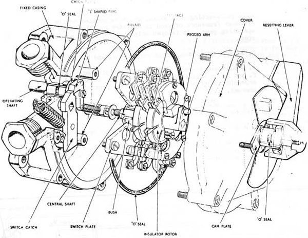
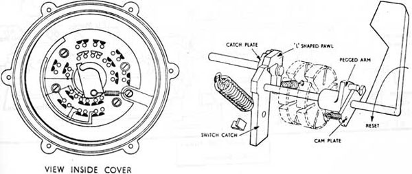
12-1-15 OPERATION OF STOP ASSEMBLY AND DISCONNECT SWITCH
1 When the top stop is DOWN, the disconnect switch can be set by moving the resetting lever towards the word RESET cast on the outside of the cover; by doing so:-
a. The resetting cam plate contacts the pegged arm and rotates the central shaft; thereby engaging the electrical contacts.
b. The switch catch plate moves, stretches its spring and is held b the toe of the L-shaped pawl.
c. The peg of the L-shaped pawl traverses the slot in the circular plate and rests against one end of the slot.
The resetting lever can then be released. Thus it will be returned to its stop, under the action of its cam plate spring.
12-29
12-1-15 OPERATION OF TOP STOP ASSEMBLY AND DISCONNECT SWITCH (contd)
2 When the top stop is being lifted on firing:
a. The operating shaft is rotated by the top stop interlock shaft.
b. The circular plate rotates and forces the toe of the L-shaped pawl away from the switch catch.
c. The central shaft then rotates, under the action of the switch catch spring, and the electrical contacts are opened.
When the top stop is replaced, the operating shaft turns and resets the L-shaped pawl in readiness to hold the switch closed when the resetting lever is put to RESET.
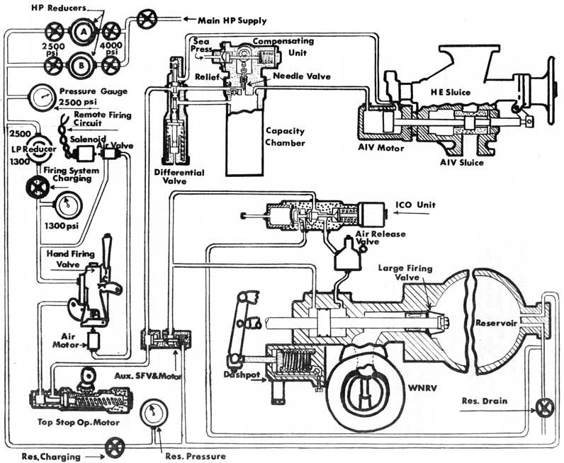
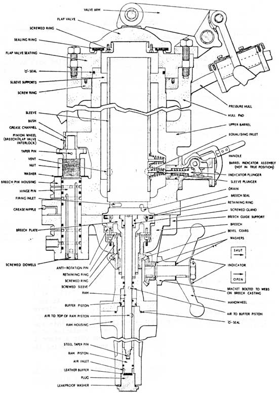
12-1-16 FIRING GEAR-(FIG 12-21)
1 INTRODUCTION
The system described in the following pages covers the "designed" arrangements; subsequent modifications may take place which will change the system as described.
The normal method of discharge for torpedoes carried in "O" class submarines, is a "swim out" release whereby the motor of the weapon is started and modified Low Pressure air system used to operate the top stop mechanism and Disconnect Switch. Once free to travel, the torpedo swims its own way out of the tube.
Weapons can be discharged from the tubes by the controlled admission of a compressed air impulse; this is cut-off when the impulse pressure has fallen to a pre-determined figure which varies according to the depth of the submarine. Before the weapon leaves the tube, the expanding air is vented into the submarine, thus ensuring that the discharge is splash less. The venting is continued until enough water has been taken in to compensate for the negative buoyancy of the weapon. This sequence is initiated by operating a hand firing lever, and it then proceeds automatically.
2 AIR SUPPLY SYSTEM
Two separate air systems are fitted: one is a high pressure system at 2500 lb/sq in; the other is a low pressure system in which the pressure varies at each tube on calibration but must be between 1200 and 1500 lb/sq in. The H.P. system operates the L.F.V. motor and an impulse cut-off (I.C.O.) unit, and also provides a constant impulse pressure for discharge. The L.P. system initiates the firing cycle and controls the venting cycle.
12-30
Fig. 12-21
Interim Dual Pressure Firing System
12-31
3 FIRING RESERVOIRS
Each tube has a firing air reservoir of 3 1/2 cu. ft. capacity.
4-way adaptor screwed into the forward end of the reservoir is sealed by a leakproof washer and has two holes in its inner end. One is the charging-pipe connection air hole, in which a pipe is screwed and sweated. This pipe is so bent that its open end is just clear of the bottom of the reservoir. Thus any water that may collect in the reservoir will be blown out first when the reservoir drain valve is opened. Each reservoir has a maximum working-pressure of 2500 lb/sq. in. and proof test-pressure of 4500 lb/sq in.
4 LARGE FIRING VALVE AND MOTOR
This unit is bolted to the firing air reservoir of its tube. It controls the rate at which H.P. air can enter the tube from the
reservoir. When its motor receives air from the aux. S.F.V. and motor
its valve opens at a rate determined by a silicone-fluid filled dashpot mounted on its body. It then passes the air to its tube via a water non-return valve (W.N.R.V.) on the tube firing pipe.
When the valve is being opened, ports allow a gradually-increasing volume of air to pass from the reservoir to the tube, via a flanged connection on the tube and water non-return valve. Through the lowest part of the body is a drain hole, water leakage from which will indicate that the L.F.V. is not airtight.
5 DASHPOT
This is filled with silicone fluid and is fitted to control the rate at which the L.F.V. will open to admit impulse air to the torpedo tube during a firing cycle. An indicator plate graduated in turns and tenths-of-a-turn is mounted on the dashpot cylinder and is aligned with an indicator attached to a needle valve, the setting of which determines the opening-rate of the L.F.V.
6 WATER NON RETURN VALVE
When a torpedo tube is flooded, water is prevented from entering the body of its L.F.V. by a water non-return valve (W.N.R.V.)
The W.N.R.V.S of tubes 3 and 4 are fitted with drain pipes so that they can drain completely into their tubes during blowing-down. Such pipes are not needed for the other four tubes.
12-32
7 IMPULSE CUT-OFF VALVE
During a firing cycle, the I.C.O. unit determines the pressure
at which the impulse air supply to the tube will be cut-off, which varies in accordance with the firing depth. The valve of the unit is constrained to open by a spring, but it is constrained to shut by both sea pressure and H.P. air pressure. It remains shut during a firing cycle until the H.P. air pressure has fallen enough for its spring to overcome the combined sea and air pressures. It then opens and supplies H.P. air to the shutting side of the L.F.V. motor, the effective piston area of this side of the motor being greater than that of the opening-side.
8 HAND FIRING VALVE
This is opened to commence the firing and venting cycles. When open, it passes L.P. air to the top stop operating cylinder from which the air passes to the auxiliary small firing valve motor. It is shut after a weapon has been discharged, and it then enables the firing and venting system fittings to vent to atmosphere and subsequently to recock. The H.F.V.s for all tubes are mounted on a panel between the tubes and are interlocked with their bow cap operating gears.
In the top end of the lever is a spring-loaded thumb push for operating. To prevent accidental operation of the valve, a feathered safety pin is fitted through quadrant and hand lever. The toes of the lifting arms are machined to suit bow cap operating gear interlock cams.
9 SOLENOID OPERATED VALVE AND MOTOR
The torpedo tubes can be fired from the Control Room. To achieve this, the hand firing valve bracket of each tube is fitted with an air motor which is supplied from a solenoid operated valve nearby. When energised by pushing a button in the Control Room, the solenoid lifts the air valve which passes air to the motor. No extra interlocks are fitted to this system because the bow-cap/H.F.V. interlock will prevent movement of the H.F.V. should the solenoid be energised when the bow cap is shut. A TUBE READY push is provided in the Torpedo Compartment so that the Torpedo Officer can inform the Control Room when a tube is ready to be fired.
10 TOP STOP OPERATING MOTOR
When this is supplied with air from the hand firing valve, it first causes the disconnect switch to open, and it then lifts the top stop and spring catch.
12-33
11 AUXILIARY SMALL FIRING VALVE AND MOTOR
After the top stop operating motor has actuated, it passes L.P. air to an auxiliary small firing valve and motor (aux. S.F.V. and motor), which is actuated by the L.P. AIR and causes H.P. air to flow to the opening side of a large firing valve motor (L.F.V. motor) and also to an impulse cut-off valve unit (I.C.O. unit). In addition it allows the L.P. air to pass to a capacity chamber, via a differential valve and a compensating unit.
12 DIFFERENTIAL VALVE COMPENSATING UNIT AND CAPACITY CHAMBER
After the top stop has been lifted during a firing cycle, L.P. air passes via the aux. S.F.V. and motor to a differential valve and a compensating unit. The air forces the differential valve downwards against the piston of a fluid-filled dashpot and is then allowed to pass to the opening side of an automatic inboard vent valve motor A.I.V. motor). This then opens to allow expanded impulse air, together with enough water to compensate for the negative buoyancy of the discharged weapon, to enter the A.I.V. tank. During this time, however, the L.P. air passes into a capacity chamber via a needle valve of the compensating unit, the setting of which is controlled by a hydrostat, i.e. in accordance with the depth of the submarine. The chamber is connected to both the shutting-side of the A.I.V. motor and the underside of the differential valve, so that when the pressure in the chamber is sufficient, the A.I.V. valve is forced shut, and the differential valve is forced upwards and causes the opening-side of the A.I.V. motor to vent to atmosphere.
13 AUTOMATIC INBOARD VENTING
A flanged pipe connection on the top of the tube rear end is joined by a 5.5 in. bore pipe to the A.I.V. tank, via a combined automatic inboard vent and hand emergency sluice valve assembly. This arrangement is for:
a. Venting impulse air inboard before it can escape from the tube, thus ensuring splashless discharge;
b. Preserving trim by admitting enough water into the submarine thus compensating for the negative buoyancy of a discharged weapon.
12-34
14 COMBINED AUTOMATIC INBOARD VENTING AND HAND EMERGENCY SLUICE VALVES
The A.I.V. sluice valve:
a. Forms a watertight valve between the sea and the submarine when the bow cap is open;
b. Opens automatically during a firing cycle and shuts automatically after an interval of time which varies according to the depth on firing;
c. When open, provides a full bore, streamlined passage for air and water being vented inboard.
The hand emergency sluice (H.E.S.) valve:
a. In normal circumstances, provides a full bore, streamlined passage for air and water being vented inboard;
b. In a emergency, provides a shut-off valve between the sea and the submarine until either the bow cap or the A.I.V. sluice can be shut.
Two valve boxes are secured together by long studs and nuts. One box houses the H.E. sluice valve and is on top of the other which houses the A.I.V. The H.E. valve is operated by a hydraulic motor bolted to its box, or by a handwheel assembly bolted to the other end. One hydraulic valve supplies the H.E. valve motors of all torpedo tubes so that, in an emergency, all six H.E. valves can be shut at once. The. A.I.V. valve is operated by an air motor bolted to its box. It is opened by air supplies from the differential valve and is shut by air from the capacity chamber.
12-1-17 OPERATION OF D.P.F.G.
1 A diagrammatic lay-out for one torpedo tube is shown in Fig
12-21. For clarity, the differential valve and compensating unit are shown separated, with the latter mounted on the capacity chamber,
whereas they are one unit. This does not modify the description of the operation of the gear and sequence of events.
2 CHARGING CYCLE
To charge the firing system and to prepare a torpedo tube for
firings:
a. The reservoir charging valve is opened, allowing air at 2500 lb/sq. in. to pass to:
(i) The firing reservoir, there it builds-up gradually to the full pressure of the inlet;
(ii) The back of the I.C.O. valve to keep the valve shut;
12-35
(iii) The inlet side of the aux. S.F.V. to assist the valve spring in keeping the aux. S.F.V. shut.
(iv) The L.P. air stop valve is opened, allowing air to pass to the inlet side of the H.F.V.
(v) The torpedo tube is flooded by 'blowing-up' water from the T.O.T.
(vi) The Bow Cap is opened
(vii) The H.E. Sluice valve is opened
(viii) The H.F.V. safety pin is removed
The torpedo tube is then ready for firing.
3 FIRING CYCLE
To fire the torpedo, the H.F.V. is operated by pulling the hand firing lever, or by pushing a button in the Control Room.
On firing:
a. L.P. air from the H.F.V. enters the top stop operating cylinder and forces over the top stop piston, thus:
(i) The top stop operating shaft rotates.
(ii) The top stop is lifted.
(iii) The disconnect switch is tripped
(iv) A port in the top stop operating cylinder is uncovered for air to pass to the aux. S.F.V. motor.
b. L.P. air enters the aux S.F.V. motor and forces over the piston thus:
(i) The aux. S.F.V. is unseated.
(ii) The L.P. air passes to the differential valve casting annulus.
(iii) H.P. air passes to the I.C.O. valve unit, but the I.C.O. valve remains shut.
12-36
b. Forces the differential valve downwards against the retarding effect of the dashpot. Thus: air passes to the opening side of the A.I.V. valve motor.
c. The A.I.V. valve opens. Its point of opening being determined by:
(i) The timing of the differential valve dashpot, which is set during manufacture and should not be altered.
(ii) The L.P. air pressure, which is set on the L.P. reducer when the torpedo tube is calibrated.
d. Air passes from the compensating unit needle valve to the capacity chamber. The setting of the needle valve is determined by its hydrostat (the depth of the submarine).
e. At a rate depending on the depth, the pressure builds-up in the capacity chamber until it is sufficient to force up the differential valve and thus:
(i) The port to the air release valve is uncovered and vents the opening side of the A.I.V. valve motor.
(ii) Air from the capacity chamber enters the shutting side of the A.I.V. valve motor and shuts the A.I.V. valve, thus completing the venting cycle.
5 RECOCKING CYCLE
When the H.F.V. is lifted on firing, either locally or from the Control Room, the hand firing lever is locked by a spring-loaded pawl and remains so until it is deliberately replaced. This is usually done immediately after the A.I.V. valve motor has been heard to vent on shutting. However the lever need not be replaced so soon after firing, but it must be replaced before the Muzzle Door is shut, or damage to the Muzzle Door interlock operating gear will result. When the H.F.V. is replaced:
a. Exhaust holes in the H.F.V. push rod are uncovered. Thus the outlet side of the H.F.V. is put to exhaust and the H.F.V. is shut by inlet air pressure and its spring.
b. The top stop operating cylinder is vented via the H.F.V.
Thus:
(i) The top stop piston is forced shut by its spring.
12-37
(ii) The top stop operating shaft rotates and resets the top stop.
c. The pressure in the capacity chamber, which also acts on the shutting sides of the differential valve and A.I.V. valve motor lifts the relief valve of the compensating unit. The air thus by-passes the needle valve and exhaust via the aux. S.F.V. MOTOR and the top stop operating cylinder atmospheric
vent.
d. When the pressure on the piston of the aux. S.F.V. motor fails.
(i) The aux S.F.V. is re seated by its spring and by pressure
remaining in reservoir.
(ii) The exhaust channel in the aux. S.F.V. is connected to atmosphere and vents both the opening and shutting sides of the L.F.V. piston. The I.C.O. valve is held open by its spring.
6 RECHARGING AFTER DISCHARGE
The cut-off pressure, which acts on both sides of the L.F.V. piston and in the I.C.O. valve chamber, may take a considerable time to vent via the small hole of the aux. S.F.V. body. During this time, the pressure in the I.C.O. valve unit will keep the air release valve of the 4-way piece shut. If therefore, the air reservoir is recharged before the system has fully vented, as might occur when firing water shots in quick succession during trials, the I.C.O. valve might shut whilst a reasonably
high pressure is still held in the shutting side of the L.F.V. motor and in
the I.C.O. valve unit. This will cause premature cut-off and therefore,
premature. shutting of the L.F.V. This is even more likely to occur at shallow depths where the cut-off pressure is higher. Confirmation as to whether the cut-off pressure is released can be gained by listening for the opening of the air release valve and hearing the air as it vents to atmosphere . However, as a further precaution, at least one minute must elapse between the firing of a shot and the commencement of charging the air reservoir for the next shot.
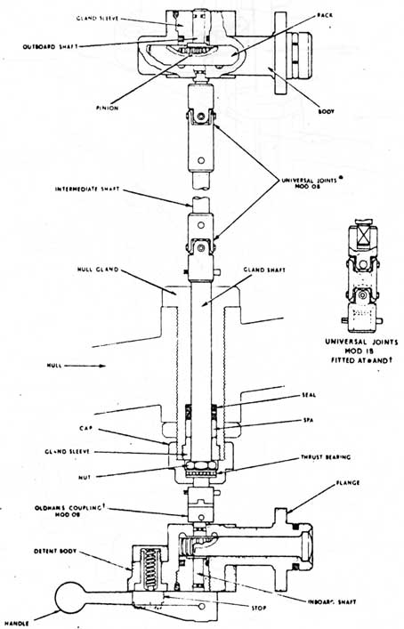
Each submarine has two torpedo tubes in its stern. They extend through No 7 main ballast tank and are numbered No 7 (Stbd) and No 8 (Fort). The tubes are short, about 12 ft. long, and are of large bore to ensure an adequate water supply to the propellers of weapons being discharged.
Each tube is sealed by a stern cap at its after end and by a rear door at its forward end. The stern cap is operated by a hydraulic ram which is on the inboard side and parallel to the tube and has an operating shaft extending through the domed bulkhead to the sterncap. The stern caps and rear doors are interlocked to prevent their both being opened at the same time. The rear door has several safety fittings to prevent it from being opened when the tube is flooded.
12-2-02 AFTER TORPEDO TUBE CONSTRUCTION
1 INBOARD AND OUTBOARD LENGTHS
Each torpedo tube comprises two lengths, namely inboard and outboard lengths. A bulkhead sleeve is welded in the dome bulkhead. It has an internal diameter of about 25 in. and is 31 in. long.
The inboard length is a forging with a flange on the after end. It has a bore of 22.5 in. and is 28.4 in. long. On the outside of the forward end is a two start buttress thread for a rear door locking ring, and the forward edge is machined to form a joint face for the rear door. On the inboard side of each tube is a pad for a hinge bracket, and opposite is a bracket for a safety swing bolt. One of two pads on the top is for stop and catch operating gear, and the other is bored for a vent pipe connection. On the bottom is formed an elbow piece for a drain pipe.
The outboard length is of 0.5 in. rolled and welded steel plate. It has an internal diameter of about 25 in. and is about 106 in. long. A flange is welded on the forward end, and a lip end is welded on the after end. It extends through No 7 main ballast tank and a 1 in. thick stiffening ring is welded around the middle. Near the ring on the top, is a pad for a stop and catch box. The lip end is welded to a spectacle plate, which in turn is welded to the after face of the tank bulkhead and carries bearings for a stern cap hinge shaft. The lip end is grooved internally to accept a test door. Aft of the tube extending from the lip end to the stern is a guide tube which is perforated to ensure adequate water flow around weapons being discharged.
2 BEARERS
To act as bearers for weapons aluminum bronze strips are riveted to the top, bottom and both sites of the tube bore. They extend from the
12-39
Fig. 12-22
Inboard Length
Fig. 12-23
Outboard Length
12-40
rear end to within 5.5 in. of the lip end. The top strip is slotted lengthwise to provide a channel for the top lugs of weapons. The bearers are machined to an internal diameter of 21.095 in.
3 STERN CAP
This is a circular steel door with a dexine seal secured to its inner face. The seal bears against the lip-end face when the stern cap is shut. The stern caps are opened and shut in the same manner as the bow caps (i.e. hydraulic rain, operating shaft, crosshead and hinge-pin top-plate). They are not fitted with any form of shutter. A stop
bracket is fitted on the centre line near the guide tubes to allow both
stern caps to be open at the same time.
4 STERN CAP INDICATORS
An indicator pointer is bolted to the inboard end of each stern cap hydraulic ram shaft. An indicator plate is bolted to each ram housing with "OPEN" and "SHUT" positions engraved on it. The indicator plates are aligned with the pointer to give a positive open/shut indications. These indicators are clearly visible and remote indicators are not necessary.
5 REAR DOORS
Both after tube rear doors are identical in construction, purpose and method of operation to those on the forward tubes. See 12-1-03 Para 10. for details.
6 STERN CAP-REAR DOOR INTERLOCKS
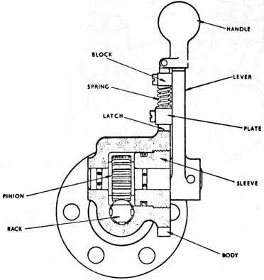
The stern cap operating gear control valves are identical to those used for the bowcaps and are fitted with the same type of operating handle operated locking bolt that locks the locking ring when the stern caps are open.
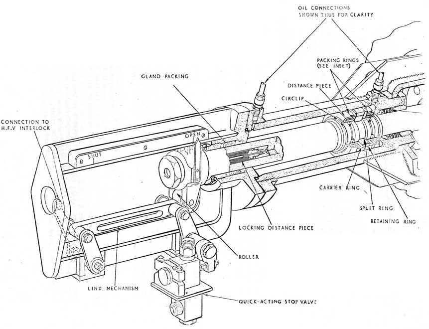
7 STERN CAP - INTERLOCK-(FIG 12-24)
A framework is secured to the inboard end of each stern cap ram housing and carries a link mechanism operated by the stern cap operating shaft. The link mechanism opens or shuts a quick acting stop valve fitted in the firing system air line. When the stern cap is opened sufficiently to allow a fired torpedo to pass, the link gear opens the quick acting air valve. Otherwise the valve is held shut by the link gear and the tube cannot be fired.
12-41
12-2-03 COUNTERMEASURE TUBE FLOOD AND DRAIN SYSTEM
1 REQUIREMENTS
For the correct working and firing of the torpedo tubes it is necessary to be able to:
a. Flood the tubes with water from a tank within the submarine, so that, on opening the stern caps no more water can enter the tubes, and therefore no change in the longitudinal trim of the submarine will result.
b. Drain down the tubes after firing, to a tank within the submarine, so that the rear doors can be opened and the tubes reloaded.
c. Allow air to enter, or escape from the tubes during flooding and draining operations.
d. Use low pressure air to pressurize the operating tank for flooding the tubes.
e. To equalize the tubes from sea and to vent hot-run generated gases overboard. These requirements are met by use of the tank, fittings and system described below.
2 TANK
Below the inboard lengths of the tubes is an internal tank that has a capacity of 800 gals. The tank fittings include a vent cock, dip rod, L.P. air blow and relief valve connections and two tube-drain valves. These two valves are near the tank top and are 2 in. bore, screw down stop valves. Each is connected by pipes to the rear underside of its torpedo tube, and is also joined to a pipe that extends downwards to the bottom of the tank.
This tank is referred to as the C.O.T. (Countermeasure Operating Tank).
3 SYSTEM
Each tube has a pipe-connection screwed in the top near the rear end. The connection is joined to two screw-down-stop valves via tin. bore pipes and a T piece. The valve nearest the tube is a hull valve, called the equalizing and hot-run valve. The other, the tube vent valve, is joined to a pipe leading to a tundish and piped to a nearby bilge.
12-42
Fig. 12-24
Stern Cap Operating Gear
12-43
Fig. 12-25
Typical Top Stop and Catch Arrangement
12-44
The equalising valve is used to admit sea pressure to a flooded tube to allow the stern cap to be opened. In the event of a hot run the
same valve is used to vent generated gases overboard. Care must be
taken when using these valves to prevent sea-water from entering the compartment.
The vent valve is located in a pipe leading from the tube to the bilge. Its purpose is to vent air from a tube during flooding-up and to admit air to the tube during drawing-down operations.
12-2-04 COUNTERMEASURE TUBE FITTINGS-
1 TOP STOP AND CATCH-(FIG 12-25)
Each tube has a top stop and catch for positioning and securing a torpedo in the bore. The top stop and catch are two circular plates . These are mounted on a shaft on the top centre line of the tube within the ballast tank and are contained in a pressure tight top stop and catch box. The inboard end of the shaft is led through the domed bulkhead to a position over the tube rear ends. By means of a handwheel the notched discs can be rotated and so set that the notches line up with the slotted top bearer strip. The positions that the discs can be set in are;
a. load position, for putting a torpedo in the tube;
b. safe position, for securing a torpedo in the tube;
c. firing position, to permit a torpedo to leave the tube.
2 DISCONNECT SWITCH-(FIG 12-26)
As with the bow tubes a disconnect switch is provided between the fire control setting cable and the torpedo in the tube. This switch is electrically identical with the forward type except for the method used to break the switch on firing.
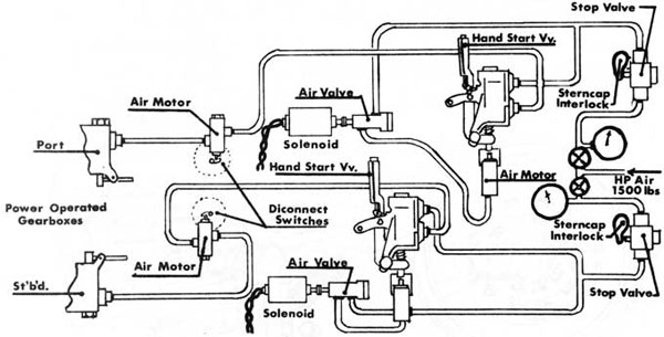
3 TOP STOP AND CATCH POWER OPERATING GEAR-(FIG 12-27)
This gear enables the disconnect switch and top stop and catch to be actuated wither from the control room or locally at the tubes. Air for the system is supplied from the H.P. air ring main to a reducer giving 1500 P.S.I. working pressure.
From the reducer the air system is comprised of the following
fittings:
a. A stop valve
b. A pressure gauge
12-45
Fig. 12-26
Mod. 0 Tube Disconnect Switch
View Inside Cover and Switch
12-46
c. A quick-acting stop valve, which is mounted on the ram cylinder framework of, and is actuated by, the stern cap operating gear. It is open only when the stern cap is wide open.
d. A three-way piece, which supplies e. and g.
e. A solenoid operated valve, which is mounted together with
f. and g. on a panel near the tube. It is actuated by its solenoid and passes air to f. when the Control Room button is pressed.
f. A hand starting valve motor, which actuates and opens g. when supplied with air.
g. A hand starting valve (HSV) which, when open supplies h.
h. A tube disconnect switch motor (T.D.S. motor), which trips the disconnect switch when it is supplied with air from g. The air then passes to j.
Fig. 12-27 CM Tubes
Air System
12-47
3 Continued...)
j. A gearbox motor containing two pistons; one piston is for operating the stop-and-catch shaft, and the other is for working an interlock shaft between the stop-and-catch shaft and a 3-piston handwheel, which must be set to READY TO FIRE before the air motor can actuate.
4 HAND STARTING VALVE
The H.S.V. of each tube is mounted on a panel near the tube and is interlocked with the Stern Cap operating gear via a stop valve in the air supply line. Each valve is housed in a vertical cylindrical casting having a boss and quadrant to take a hand lever, and also a bracket to secure the unit to a panel. The casting is bored vertically and has two sweated and screwed pipe connections. One near the top is the inlet and is connected to the air supply, and the other is the outlet and is connected to the gear box air pressure inlet via the T.D.S. air motor.
When the H.S.V. is opened:
a. Air enters the cylinder and forces the piston downwards against its spring.
b. The piston spindle strikes the switch trip lever, thereby breaking the control circuits of the torpedo.
c. The piston seals off the atmospheric port, but the outlet port is uncovered for the air to pass to the gearbox air motor.
When the H.S.V. is shut:
d. The piston is forced against its spigot by its spring. a. Air exhausts from the gearbox motor via the atmospheric vet.
f. Air exhaust from the top end of the cylinder via the H.S.V.
g. The piston spindle clears the switch trip lever, in readiness for the switch mechanism to be re-set by hand.
5 ARRANGEMENT OF STOP-AND-CATCH AND TRIPPER SHAFTING
For power-operated starting gear, the stop-and-catch and tripper shafts are arranged differently from those for hand-starting gear. The pedestal bearing is omitted from the intermediate shaft of the stop-and-catch, but an adaptor is keyed on the forward end of this shaft and is
12-48
5 Continued...)
coupled to the forward shaft by a flexible coupling. This coupling allows for any misalignment between the two shafts, and for any deflection due to compression of the pressure hull. The adaptor is spaced from the forward shaft by 1/8 in., both stars of the coupling are keyed on their shaft. The forward shaft is coupled to a shaft protruding from the power-operated gearbox. The halves of the coupling are pinned to their shafts and are bolted together. As well as a stern cap interlock flange, the forward shaft has a tripper operating flange pinned to it.
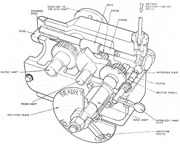
6 GEAR BOX-(FIG 12-28)
This is mounted on a pad near the tube rear end and is closed by an end-cover plate bolted to it. It has three shafts, namely an input shaft, a pinion shaft, and an output shaft. These are pressed in housings formed in the after end face and in the end coverplate, which is dowelled for accurate alignment of the bushes.
Fig 12-28
Gearbox C.M. Tubes
12-49
6 Continued...)
The input shaft has both a gearwheel and interlock plate keyed on its inner end. It extends through a flanged housing bolted to the end cover plate and has an indicator pointer keyed and secured by a washered nut on its outer end. A circular indicator plate is secured by screws to a flange on the forward end of the flanged housing and is engraved LOAD, READY TO FIRE, and FIRED. These positions correspond with three semicircular grooves in the rim of the interlock plate. A handwheel some distance forward of the tube is connected to the outer end of the input shaft by rods that are linked with universal couplings covered with grease-filled rubber sleeves. A slot through the forward end of the waisted-spindle engages the toe of an interlock lever, which pivots about a pin in a bracket on one corner of the box. Within the box, a spring surrounding the forward length of the waisted-spindle holds a washer against a collar on the spindle and constrains the waisted-length away from the interlock flange. Thus, before the 3 position handwheel can be turned, the interlock lever Lust be depressed to bring the waisted-length into line with the flange. Because the interlock lever is so close to the stern cap operating gear, a spring-loaded push is mounted on a
bracket bolted to the indicator plate and enables the lever to be depressed without risk of injury to the operator.
12-2-05 OPERATION
1 Assuming that the handwheel is at READY TO FIRE and the stern
cap is wide open then, when the H.S.V. is opened:
a. Air passes to the disconnect switch motor and trips the disconnect switch.
b. The air then passes to the gear box motor cylinders.
c. The waisted-spindle is forced forwards and thus frees the interlock flange of the input shaft.
d. The rack piston rod is forced against its stop. It rotates the gears and thus turns the indicator pointer to fired.
e. The stop-and-catch rotates and frees the torpedo.
When the H.S.V. is shut:
f. The gearbox motor cylinders vent to atmosphere via the disconnect switch motor.
g. The waisted-spindle is forced aft by its spring and resecures the interlock flange.
12-50
NOTES
1 The interlock lever must be depressed before the handwheel can be moved from FIRED to LOAD, and from LOAD to READY TO FIRE.
2 The action of turning the handwheel from LOAD to READY TO FIRE returns the rack piston rod to the beginning of its stroke, in readiness for the next discharge.
12-51
12-3-01 EMBARKING STOWING AND LOADING
1 ARRANGEMENTS FORWARD
Weapons for the bow torpedo tubes are stowed in the Forward Torpedo Room; they are embarked via a loading hatch which is near the after end of the compartment and its entrance faces aft. Each weapon is lowered by a shore side crane on to a pair of portable rails which are rigged on the fore-casing and extend through the hatch into the compartment. Once a weapon has been embarked it is transferred from the rails to its stowage by using a lifting winch, an overhead transporter, and traversing and loading gear. The lifting winch and, in par, the traversing gear and loading gear are hydraulically-operated but, lest hydraulic power should fail, weapons can be traversed by hand, and hand-loading gear is provided.
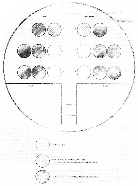
2 STOWAGES-(FIG 12-29)
A full outfit of weapons comprises 18 torpedoes. Six are
stowed in the tubes, and 12 are stowed on trolleys on transverse trolley paths abaft the tubes. There are three tiers of trolley paths to each side of the compartment; the bottom tier comprises four equi-spaced pairs of trolley paths, and the top and middle tiers each comprise four equi-spaced single trolley paths. The bottom tier trolley path are resiliently mounted on J-straps bolted to the deck, whereas those of the top and middle tiers are resiliently mounted on J-straps which are bolted to girders welded to the pressure hull frames. The top face of each path is just below the bottom centre-line level of its respective torpedo tube.
The inboard lengths of the top and middle tier trolley paths are hinged to their outboard lengths and are termed 'hinged bearms'; they are swung horizontally into line fore-and-aft and secured before weapons are embarked, thus providing maximum clearance for handling weapons in the gangway between the inboard ends of the beams. When the hinged beams are aligned with their trolley paths they are locked by pins, and by adjustable horizontal stays pinned between the inboard ends of the beams. Horizontal stays are permanently pinned between adjacent trolley path pairs, and between the forward and after trolley paths and their adjacent pressure hull frames. Gauges are provided for checking that adjacent hinged beams are spaced correctly for trays to be fitted between them. This check must be done after every occasion of embarking weapons.
Each top tier can accommodate two weapons abreast, and each middle or bottom tier three abreast; usually, however, two only are fitted to each tier, thus the inboard weapon of each top tier is in line with a torpedo tube, whereas the stowages abaft tubes Nos. 3 to 6 are left empty.
12-52
FIG. 12-29 STOWAGE OF TORPEDOES
12-53
3 TRAVERSING GEAR, BOTTOM TIER
Mid-way between and parallel with the trolley paths of each pair is a screwed shaft which is driven, through shafting and gearing, by a hydraulic motor; one motor is fitted for the port, and one for the
starboard tier. The outboard, or 'driving' trolley of each pair of trolley paths is engaged by its screwed shaft; thus it can be traversed both
inboard and outboard. Each driving trolley has a 'driven' trolley pinned to its inboard side. When empty, driven trolleys can be readily unpinned, then be removed from their paths and placed in stowages. To secure
trolleys in fore-and-aft line with the torpedo tubes, i.e. the 'loading positions' auto stops are fitted to the top faces of the trolley paths and can engage in recesses in the forward and after sides of the trolleys. They engage automatically but must be withdrawn by pulling hand levers at the inboard ends of the paths. Other auto stops are similarly fitted to secure trolleys in the stowage positions adjacent to the loading positions, but none are fitted to the outboard stowage positions. Hand levers for the stowage position stops are fitted to the underside faces of the trolley paths, outboard of their stops.
4 LOADING GEAR FOR BOTTOM TIER
At the after end of the compartment and in line with the torpedo tubes are two sets of loading gear, one for the port, and one for the starboard loading positions. To form continuous paths for weapons in the
loading portions, the gaps between the torpedo tubes and the foremost hinged beams, between adjacent pairs of hinged beams, and between the aftermost hinged beams and the loading gear sets, are bridged by forward trays, collapsible trays, and fixed trays respectively. The forward trays are removable for tube rear doors to be shut, and the collapsible trays can be lowered for weapons to traverse them. The fixed trays are secured to
brackets near the after end of the compartment. Trays of one other type are also provided; these are 'portable trays' and are for filling the gaps between the hinged beams when all trolleys are in use. They are secured by the auto stops and can be fitted or removed only when the loading positions are empty.
Torpedo tube Nos. 5 and 6 only can be 'power-loaded'. Each has a hydraulic motor which drives gearing in a crosshead, through a vertical splined shaft. A slipper carried on the forward end of the crosshead is secured to one end of a chain engaging with a sprocket driven by the crosshead gearing. The free length of chain hanging from the sprocket emerges vertically from the crosshead and enters and coils into a chain case below. To power-load a weapon, a tail bar attached to the slipper is connected to its horizontal fins, and the chain is then driven forward until it is fully loaded into the torpedo tube; the tail bar must then be disconnected by hand and be withdrawn by the chain.
12-54
5 TRAVERSING GEAR, TOP AND MIDDLE TIERS
The trolleys of top and middle tiers have to be traversed by hand. When in use they are locked on their trolley paths, in either stowage or loading positions, by means of latch-operated bolts which are attached to their undersides and engage in 'stowage' slots cut in the edges of the trolley paths. More slots are cut in the edges of the paths, except in the forward edges of the paths, except in the forward edges of the forward trolley paths and the after edges of after trolley paths. These extra slots are termed 'braking slots' because they prevent trolleys from 'taking-charge' when weapons are being traversed. To do so, they engage spring-loaded plungers which are fitted in the ends of traversing bars. Two such bars are provided: one for fitting between the two forward, and the other for between the two after trolleys of the four supporting a weapon to be traversed. When a traversing bar is rigged for use, its plungers are secured in holes in the side frames of its trolleys. They extend through these holes into braking slots and thus enable the latch-operated bolts to be withdrawn without freeing the trolleys. To free the plungers, two levers fitted to each bar must be finger-operated while the bar is grasped for pushing the trolleys. The plungers, however, are spring-loaded and will re-engage in the braking slots as soon as their levers are released. Each traversing bar is long enough for two men to push it if necessary.
6 LOADING GEAR FOR TOP AND MIDDLE TIERS
Weapons are loaded from the top and middle tiers into tube Nos. 1
to 4 by a method called 'Power Assisted Loading'. This method entails
hauling each weapon into its tube by a wire-rope, which is connected to the
weapon by a loading bar and is winched by a drum. The drum is carried on
an extension of the chain sprocket shaft on the crosshead and is powered
by the same hydraulic motor as that used for power loading of the bottom tier.
The winch drum is controlled by a sliding clutch, which is permanently
keyed and screwed to the chain-sprocket shaft extension and is operated by
a springloaded lever. Before the clutch can be engaged, the slipper must
be fully retracted and locked. The weapon is loaded by hauling-in on the
winch drum while veering on a tail tackle secured between the weapon loading
bar and an eye-plate on the after bulkhead.
After a weapon has been traversed to a loading position in the top or middle tier, a continuous loading path must be formed by fitting fixed trays between adjacent trolleys or portable trays, between the forward trolley and the vertical support, and between the vertical support and the torpedo tube. The fixed trays are secured to the trolleys, portable trays, or vertical support by drop-nosed pins, and the forward end of the forward fixed tray is machined to fit in the breech door locking ring of its torpedo tube.
12-55
7 LOADING CONTROL POSITIONS
Each set of loading gear has two control positions; one is near the tube rear doors, and the other is aft near the bulkhead. Both positions are manned while weapons are being loaded.
12-3-02 EMBARKING ARRANGEMENTS
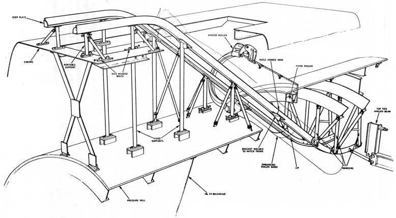
1 EMBARKING RAILS-(FIG 12-30)
Before weapons can be embarked, a pair of embarking rails must be rigged, leading from the casing through the loading hatch into the torpedo compartment. They are of steel angle-bar with lips welded to their inner edges, and stops welded to their inboard and outboard ends. The lips form paths for the rollers of a weapons-embarking band, and the stops prevent the band' from running off the rails. For ease of handling and stowing, they are in two sections, joined at brackets bolted to the inside of the embarking hatch trunk. Their outboard lengths are secured to vertical supports by countersunk-headed bolts and nuts. Some vertical supports are portable and remainder fixed. The portable types are braced by stays pinned to them, and are secured to pads on the casing and pressure hull by vice-headed bolts. To prevent their being lost overboard, these: bolts are wired to their supports. The fixed supports are secured to pads on the casing and pressure hull by set bolts. Two are braced by crossed stays pinned to them. The inboard lengths of the rails are supported by three pairs of hangers and stays which extend from the three hull frames forward of the loading hatch. An extra pair of stays extends from lugs bolted to the edges of the rails and is pinned to the fixed lengths of the top tier stowage beams. Thus, when the rails are rigged, the hinged beams cannot be moved. All, the embarking rail fittings are galvanised. When not in use, they are stowed in rattle-proof stowages between the casing and the pressure hull.
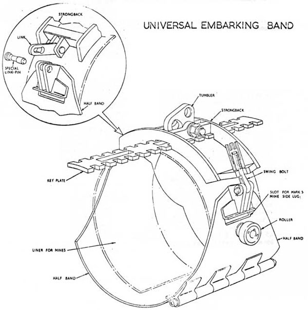
2 EMBARKING BANDS-(FIG 12-31)
a. Before a weapon is lifted, an embarking band must be clamped around its middle. The bank is then shackled to an embarking pendant which is attached to the hook of s shore-side crane. Rollers fitted on either side of the bank run on the embarking rails and take the weight of the weapon as it is embarked. On the top centre of the band are lifting lugs to take a drop-nose lifting pin which carries a lifting tumbler. This has three eyes, one for the lifting pin, one for the embarking pendant shackle-pin, and one for the pin of a lifting press wire shackle. This shackle is connected to the band after the weapon has been lowered into the compartment.
12-56
FIG. 12-30
TORPEDO EMBARKING RAILS
12-57
b. Lightweight lifting band - During embarkation each weapon is
lifted from the embarking rails by overhead lifting gear and then rested on portable cradles between the beams. The embarking band is then removed and is replaced by a lightweight lifting band. This type of band is used to lift and transport all weapons inside the submarine. It is articulated and easy to handle, but it must be treated with care to protect it from damage or distortion.
Universal Embarking Band
Fig 12-31
12-58
3 EMBARKING PENDANT
This is an E.S.F.S.W. rope with an eye at each end. It is long enough to ensure that the hook of the crane is clear of the embarking hatch coaming when the embarking band rollers bear against the stops at the inboard ends of the rails.
4 ROLLERS
As it passes through the embarking hatch, the embarking pendant is guided by two rollers. The first is carried on a hinged, crescent-shaped arm which is pinned to a bracket welded on the lip edge of the hatch coaming; it can be hinged back and pinned to avoid the hatch lid when it is not in use, or it can be pinned in its after position to guide the pendant through the hatch when weapons are being embarked. The second roller is pinned to a bracket welded on the top centreline of the Torpedo Compartment, to guide the pendant clear of the pressure hull frames. The bearing pins of both rollers are fitted with grease nipples.
5 OVERHEAD LIFTING GEAR
This is used to convey weapons from the embarking rails and land them between or on the trolley paths. It is carried on a gantry comprising a pair of beams resiliently mounted on brackets welded across the faces of Fr. Nos. 26 and 27. A toothed rack is secured to the top face of the forward beam and engages with a set of gears in a trolley. This is carried on the beams and can be moved athwartships by turning a chainwheel driving the set of gears. For securing the trolley in any desired athwartships position, a locking device is fitted to its underside. Between each end of the pair of beams is a sheave guiding a lifting winch wire. The wire passes over sheaves in the trolley and carries a lifting sheave block suspended below it. The starboard end of the wire is anchored to a bracket welded between Fr. Nos. 26 and 27.
6 HYDRAULIC WINCH DISC BRAKE TYPE
This consists of a McTaggart Scott, Mk. 5, Series 2 Hydraulic Motor driving a spirally grooved concentric drum, through planetary gears. The motor shaft is secured to two pedestals welded to a bed plate which is resiliently mounted to port, between Fr. Nos. 26 and 27. The winch can lift 1 ton 7 cwt. when supplied with oil at a pressure of 1800 lb/sq.in. The lifting rope is secured to and wound round the drum which can accommodate
45 ft. of 1 3/4 in. 6/37 E.S.F.S.W. rope. The winch assembly is protected
by a sheet-metal guard.
12-59
12-3-03 ARRANGEMENTS AFT
Weapons for the after tubes are embarked on rails similar to those used for weapons forward. Two weapons are stowed in the tubes, and stowages for two more are provided, on either side of the After Ends. The weapons are stowed and loaded by using a hydraulic lifting press, overhead trolleys and hand loading-gear.
12-3-04 EMBARKING PROCEDURE FORWARD
1 PRECAUTIONS WHEN EMBARKING OR DISEMBARKING
a. Nose and tail lines must be attached for guiding and steadying each weapon.
b. For electrically-powered weapons, starting lever safety chocks must be sighted in place (R.N. torpedoes only).
c. Torpedo propeller guards must be fitted.
d. When loading a weapon into its tube, the first movement of lifting the spring catch and loading against the top stop must be performed with great care to prevent damaging the top stop.
2 PORTABLE EQUIPMENT REQUIRED
a. 1 set of Embarking Rails and associated fittings:
- Embarking Pendant
- Weapons Embarking Bands
- Lightweight Lifting Bands
- Portable Rails
- Trays and cradles
- Tackles for positioning weapons fore-and-aft
b. 1 set of gear for power-assisted Loading and withdrawing
c. Hand Loading Gear
3 PREPARATION will include these actions:
a. Ensure that all bow caps are shut, and that all tubes are drained and clear.
b. Rig rails
c. All traversing and ramming gear.
12-60
3 Continued...)
d. Rig the embarkation rails. For ease of assembly, do not tighten the supports and stays until all components have been loosely erected.
e. Secure the rollers in position.
f. Remove all unnecessary gear from the Torpedo Compartment.
12-3-05 ARRANGEMENTS FOR HANDLING MK 37 TORPEDOES
1 In addition to British weapons, O-class submarines of the R.C.N.
can also discharge U.S. Mk. 37 Mod. 1 torpedoes from their bow tubes, and Mk. 37 Mod 0 from their countermeasure tubes. These torpedoes are only 19 in. in diameter, and they have bearer strips secured along their bottom centrelines; in consequence, R.C.N. submarines are supplied With extra equipment, and some of their standard O-class fittings have had to be modified.
2 MK 37 TORPEDO LOADING BARS
Three different types of Mk. 37 loading bar are provided:
a. Bottom Tier Type for the power-loading and hand-loading of tubes 5 and 6; this bar can be coupled direct to either ramming gear slipper for power-loading, or be fitted with a special crosshead for hand-loading.
b. Top and Middle Tier Type for the power-assisted loading and hand-loading of tubes 1 to 4.
c. Countermeasure Tube Type for the hand-loading of tubes 7 and 8.
3 BOTTOM TIER TYPE
The main components of the bar are two, long steel tubes, one of which is fitted inside and is longer than the other. The outer tube is externally threaded at its after end, and has welded on its forward end a housing, to the bottom face of which a forked lug is secured by four countersunk-headed screws. A similar lug is secured to a sleeve, which is pinned on the after end of the inner tube and is threaded to suit the wing nuts of the power-loading gear slippers, and also to suit the captive nut of a special hand-loading crosshead. A screwed cap to protect the sleeve threads is provided for use when the loading bar is idle.
12-61
3 Continued...)
A forward leg is secured to the forked lug of the outer tube by a split-pinned pivot pin; and a rear leg is similarly secured to the forked lug of the sleeve. A shoe to ride over the bottom strips of the loading gear trays and trolleys is secured to the forward leg by a split-pinned pin, about which the shoe can pivot. The base of the after leg is shaped to fit in the lugs of loading gear slippers and is drilled to take the securing pin of a special shoe used during hand-loading, when the slippers are not utilised. The legs are kept vertical to support and guide the bar during use, but they can be retracted inwards to rest against the outer tube at other times; to keep them engaged in both their retracted and extended positions, each is fitted with a spring-loaded knurled barrel, which must be pulled to release its leg, but it resets automatically when released.
A clamping pin is retained in the forward end of the inner tube
bore by a screwed pin that extends through two diametrically-opposite slots
in the inner tube; and three claws are secured to the forward end of the
inner tube by three dowel pins, about which the claws can rivet. A knurled
nut sere wed on the after end of the outer tube is fitted over a thrust ring
pinned on the inner tube, and it is retained thus by an internal circlip.
When the loading bar is in use and knurled nut is rotated anti-clockwise,
the outer tube moves forward and closes the claws, which enter the recess
of a button on the after end of the torpedo, while the clamping pin is forced
against the end of the button; alternatively, the button is released when
the nut is rotated clockwise. The distance between the claws and the clamping
pin is set during assembly while the claws are engaged; it is determined by
a shim placed under the head of a bolt screwed in the clamping pin.
The special crosshead for hand-loading comprises a steel tube with a captive knurled nut on its middle, with an eye for the shackle of a preventer tackle, and with a pulley on each of its ends. To accommodate the preventer tackle wire, a slot is cut in the shackle eye bracket and must be uppermost when the crosshead is in use.
4 TOP AND MIDDLE TIER TYPE
This is similar to the bottom tier type, but it is permanently fitted with a crosshead and has different shoes to suit the top and middle trays and trolleys.
5 COUNTERMEASURE TUBE TYPE
This is similar to the top and middle tier type, but it is shorter and is not fitted with legs and shoes.
12-62
6 LIFTING BAND FITTINGS
Six ferodo-faced hardwood liners are provided for use with each weapon-embarking band during the embarkation of Mk. 37 torpedoes; they must be secured to the inner surface of their band with countersunk-headed screws Special Mk. 37 adaptors are provided for use with the lightweight lifting bands; they are of a similar design to the mine adaptors, but their U-clips are of a aluminum-alloy, not steel and, to keep them in the correct order for ease of fitting, they are linked together with lengths of plastic-covered wire.
7 BOW TUBE LOADING GEAR FITTINGS
a. Bottom Tier Trolleys. When these are to be used for Mk. 37 torpedoes, extra large rollers must be screwed into their mine-roller bosses. The eight trolleys used on the two forward pairs of trolley paths are each permanently fitted with two spring-loaded plungers to engage and guide the bottom bearer strips of Mk. 37 torpedoes. The plungers do not interfere with other weapons, nor with the loading gear slippers; they are merely depressed clear by these during loading.
b. Bottom Tier Forward Trays. One pair of large rollers must be screwed into the mine roller bosses of each of these trays before they are used for Mk. 37 torpedoes.
c. Bottom Tier Forward Collapsible Trays. Each of these must also be fitted with one pair of large rollers before they are used for Mk. 37 torpedoes.
d. Bottom Tier Portable Trays. In R.C.N. submarines only, these trays are fitted with four mine-roller bosses each, into which large rollers must be screwed before they are used for Mk. 37 torpedoes. In addition, each tray is fitted with two spring-loaded plungers, which are similar to those fitted to the bottom tier trolleys.
e. Top and Middle Tier Trolleys. Before these can be used for Mk. 37 torpedoes, special tufnol-faced aluminum blocks must be placed in their mine-roller sockets. The tufnol facings are machined to a radius of 9.5 in. and are chamfered at their ends.
f. Top and Middle Tier Forward Trays. One Mk. 37 keel block and four large rollers are provided for use with each of these trays. The keel block is used to support and guide the bottom bearer strips of the torpedoes; it is of U-section aluminum-alloy bar and must be secured to the after transverse frame of its tray by means of a drop-nose pin.
g. Top and middle Tier Fixed Trays. Each R.C.N. submarine is supplied with two of a special type of fixed tray for use with Mk. 37 torpedoes. These two trays must be fitted in place of the two forward standard-type trays of the loading position to be used; they differ from the standard type inasmuch that their side rubbing strips are thicker and are faced with tufnol machined to a radius of 9.5 in. and also that they have U-section aluminum-alloy channel bars secured to them, instead of
12-63
7 g. Continued...)
bottom bearer strips.
h. Top and Middle Tier Portable Trays. For these to be used with Mk. 37 torpedoes, steel cheek plates to retain wooden bearer chocks must be secured to them with drop-nose pins, each R.C.N. submarine being supplied with enough of these fittings to adapt four trays.
j. Top and Middle Tier Outrigger. This comprises an aluminum-alloy girder with a channel bar secured to its top face by countersunk-headed screws. It is used to support the rear leg of a Mk. 37 loading bar when tube 1, 2, 3 or 4 is being loaded. When in use it is secured with a drop-nose pin to a lug on the after face of a trolley on the trolley path at Fr. 30, and the loading bar foot is engaged in its channel bar; it is kept level by a packing piece welded to the lower edge of the trolley path beam. One outrigger is supplied to each R.C.N submarine.
k. Stowages. One torpedo can be stowed on each side of the after compartment, against rubber-faced brackets welded to Frs. 111 and 113. The port brackets span the air ram cylinder of a submerged signal ejector, which limits the available stowage space, so the port reload is secured parallel with the centreline. The starboard brackets are not so restricted; they therefore allow the starboard reload to lie parallel with the pressure hull and thus provide maximum working space between the stowages. This arrangement means that the starboard landing bars meet the feet of their stowage brackets at an angle when they are rigged, but the trolley rollers are small enough to negotiate the angles with ease. Adjacent to the heads and feet of the stowage brackets are anchor brackets for flexible steel securing straps, which are used to secure the reload torpedoes in the stowages. Each strap comprises two half-straps joined with a bottle screw, for which a special spanner like a carpenter's brace is provided.
8 RIG FOR POWER-ASSISTED LOADING-Ref BR 2226(5) FIGS 8C and 8D
The rig for the loading of tubes 1 to 4 with Mk. 37 torpedoes from the top and middle tiers is shown in Fig 8C: two haulin-in clamps are secured to the rear door locking ring and are positioned as shown in Fig 8D; the shackle-end of the 103 ft long loading pendant extends through the removable pulley of one clamp and is secured to the eye of the other; the bight of the pendant extends aft through the loosened securing bands and around the pulleys of the loading bar crosshead; the free-end of the pendant extends aft and passes around the platform bracket sheave, thence down to the winch drum; the backhaul is fitted between the eye of the loading bar and the eyeplate of a bulkhead stiffener in line with the tube; and the free-end of the backhaul runs from aft to forward.
12-64
9 RIG FOR HAND-LOADING FORWARD-REF BR. 2226(5) FIG 8C
The rig for the hand-loading of tubes 1 to 6 with Mk. 37
torpedoes from any tier is similar to that shown in Fig 8C for power-assisted loading, except that an 86-ft. long pendant is used and is not passed around the platform bracket sheave, nor around the winch drum.
10 RIG FOR HAND-LOADING AFT -REF BR.2226(5) FIG 8E
The rig for the loading of tubes 7 and 8 with Mk. 37 torpedoes is shown in Fig. 8E: two hauling-in clamps are secured to the rear door locking ring and are positioned as shown in Fig 8D; the strops, (C) and (H) to port, or (D) and (E) to starboard, are shackled to eyeplates on Fr. 108; the backhaul is secured between the eye of the loading bar and the triangular link of the strops, with its free-end running from aft to forward; the shackle-end of the 36-ft. long loading pendant extends through the removable pulley of one clamp and is anchored to the eye of the other; the bight of the pendant extends forward and around the pulleys of the loading bar crosshead; and the free-end of the pendant runs from aft to forward.
12-65
PART 12 SECT 4
12-4-01 SUBMERGED SIGNAL EJECTORS
GENERAL
All Canadian "O" class submarines are fitted with two submerged signal ejectors (S.S.E.s), one each in the forward and after torpedo rooms. The S.S.E.s provide a method of releasing a variety of pyrotechnic signal devices and countermeasure decoys from within the submarine.
There are three types of S.S.E.s:
S.S.E. MK 2, fitted in the FTR and suitable for RN stores only.
MK 4, fitted in the ATR and suitable for both RN and USN stores.
S.S.E. MK 7, designed to replace MK 2, suitable for USN stores only.
12-4-02 S.S.E. MK 2-(FIG 12-32)
This ejector is designed to discharge pyrotechnics and decoys of U.K. manufacture down to Max. diving depth, silently and without giving visible indication on the surface.
The primary method of discharge was originally intended to be by air operated ram with air "bubble" discharge as a secondary method. At present all stores are suitable for air discharge only and therefore the ram feature is not normally used.
The air pressure in both cases is supplied by a sea operated reducer giving an output of 200 P.S.I. above sea pressure.
The ejector consists of a barrel with a 6 in. internal diameter which fits on a pad piece welded to the pressure full. At the outboard end a flap valve shuts the barrel off from the sea. At the inboard end is the breech to which is attached the ram assembly. A loose sleeve of 4 in. bore inside the barrel can be raised or lowered by operating the selector valve to select air or ram discharge. When firing by ram this sleeve is positioned in the raised position. This allows a free circulation of water between the sleeve and the barrel to prevent a vacuum when a store is discharged. For air discharge the sleeve is lowered, thus restricting the firing air to the inside of the sleeve.
A plunger operated by a lever on the outside of the barrel gives an indication of whether or not the store has been discharged.
12-66
Fig. 12-32
SSE. MK. 2
GENERAL ASSEMBLY
12-67
12-4-03 S.S.E. MK 2 ASSEMBLY-(FIG 12-33)
1 MULTI VALVE UNIT
A. group of four lever-operated valves provided to flood , drain, vent and fire the ejector and positioned at least 12 in. below the breech asst'. to facilitate gravity draining.
a. Drain valve. Connected to a pipe from the lower end of the barrel.
b. Vent valve. Connected to a pipe fitted between the barrel and the sleeve with its orifice at the top of the barrel.
c. Equalizing valve. Connected between the lower end of the barrel and a hull valve. Enables the barrel to be flooded up and equalized to allow opening the flap valve.
NOTE.
The construction of the drain valve and equalizing valve operating levers is such that the vent valve is operated on the same movement.
FIG. 12-33
MULTI-VALVE UNIT
12-68
d. Firing valve. This admits air from the firing reservoir to the selector valve which is positioned for air or ram firing.
2 THE RAM
The ram housing is attached to the underside of the breech. The ram rod is positioned in the centre of the breech where it is sealed by an "O" seal. The ram rod is screwed to a piston which works inside the ram housing. Where necessary the ram is made air tight by "O" seals to prevent air escaping from the firing side to the re-cock side and vice versa. A buffer piston is fitted at the top of the ram piston bore to retard the ram movement and to suppress noise. A leather pad is fitted at the bottom of the ram bore to cushion the piston on the re-cock cycle and to prevent noise.
3 THE BREECH
The breech moves horizontally and is pivoted on a hinge Tin secured in a cast projection on the side of the barrel. The breech pin is secured to the breech casting and pivots when the breech is moved. The air supply for operating the ram is channelled through ports in the breech pin which are lined-up only when the breech is properly shut. This ensures that the ram cannot be operated accidentally when the breech is open.
A spring loaded locating pin on the side of the breech mates with a hole in the barrel casting and ensures the breech is properly aligned when shut. The pin is removed by a lever to free the breech for opening.
In the centre of the breech plate is a short sleeve which is moved up or down by a gear and handwheel assembly. This sleeve is moved upward against the bottom of the barrel to form a seal when the breech is shut, and moved downward to release the breech for opening. Around the outer edge of the sleeve is a neoprene seal that forms a watertight joint when the sleeve is forced against the bottom of the barrel.
4 FLAP VALVE-(FIG 12-35)
A cast-steel dish-shaped cap with a neoprene seal secured to its inside perimeter mates with the top of the barrel and is referred to as the flap valve. This flap valve is operated by a gear and link mechanism interlocked with the breech to prevent both from being opened at the same time. The flap valve operating gear is constructed to allow any excess pressure in the barrel to escape when the flap is shut. The flap valve operating mechanism is fitted with a remote shutting release to shut the flap in the event that the operator cannot use the normal method.
12-69
5 INTERLOCKS
a. Cam operated interlock valves. Two poppet valves operated by the flap valve operating mechanism. One of the valves ensures that air cannot be supplied to the firing lever until the flap valve is fully opened. The other valve opens as the flap valve is shutting and supplies air to ensure that the ram is returned to the housed position before the flap valve is fully shut and the breech free to open.
b. Mechanical interlock between the breech and the flap valve permitting only one to be opened at a time.
c. Breech hinge pin air ports. These ports supply air for operating the ram only when the breech is fully shut.
Fig. 12-34
Breech/Flap Valve Interlock
12-70
FIG.12-35
SSE. MK.2
BREECH & FLAP VALVE
12-71
12-4-04 OPERATION OF S.S.E. MK 2
1 PROCEDURE FOR FIRING BY AIR.
a. LOADING.
i. Move selector valve handle to the AIR Position
ii. Charge the firing reservoir
iii. Check ejector drained down.
iv. Open the breech and inspect the bore.
v. Insert the pyrotechnic
vi. Shut the breech, ensure that the locking pin
vii. is engaged, screw the breech seal up tight.
viii. Check the Equalizing Hull valve open. (Should be opened during Opening up for Diving).
ix. Open the Equalizing valve on the Multi valve unit, until a full bore of water comes from the vent, then shut.
x. Report, "Forward S.S.E. loaded with a ______.
b. FIRE
At the order "Fire the Forward S.S.E.", repeat the order and;
i. Open the flap valve
ii. Pull the firing valve
iii. Operate the indicator plunger to check that the store has been discharged.
iv. Report "Forward S.S.E. fired".
c. DRAINING DOWN
i. Shut the flap valve
ii. Move selector valve handle to RAM position and operate the drain/vent handlever.
iii. When drained down, open the breech, remove the pyrotechnic baseplate and then inspect that the bore is clear.
iv. Report "Forward S.S.E. drained down, bore sighted clear."
NOTE
The baseplate on most pyrotechnics are fastened to the body by small lead sheer pins. When the pyro is fired the lead pins shear off allowing the pyro to float clear. Small bits of lead from these shear pins accumulate on the breech plate and in the breech area causing leaks during flooding-up operations. Care should be taken to ensure that these bits of lead are removed after firing.
12-72
2 FIRING BY RAM- (FIG 12-36)
a. LOADING
i. Move selector valve handle to RAM position.
ii. Charge firing reservoir.
iii. Check ejector drained down.
iv. Open the breech, check the bore clear.
v. Insert the pyrotechnic. Ensure that it is a type suitable for RAM discharge.
vi. Shut the breech, ensure locking pin engaged.
vii. Operate the equalizing/vent handlever. When equalized open the flap valve.
b. FIRING
i. Pull the firing lever, listen for the ram.
ii. Operate the indicator plunger and ensure that the pyrotechnic has been fired.
iii. Shut the flap and listen for the ram to return.
iv. Drain down.
NOTE
Observe the same reporting procedure on RAM as used for AIR firing.
FIG. 12-36
SELECTOR ASSEMBLY
12-73
12-4-05 S.S.E. MK 4
The S.S.E. MX 4 is fitted in the ATR of all Canadian "O" class submarines. The model fitted is the MX 4 1B.
This S.S.E. is designed to eject stores by sea-water forced into the barrel by an air-pressure operated water-ram. This method of firing is called "Water-Ram Discharge" and has several advantages over the air impulse method. The Mk 4 can eject stores down to any depth at which the submarine can operate and does not make any indication on the surface such as bubbles. Both U.S. and U.K. manufactured pyrotechnic and countermeasure stores can be discharged. As U.S. stores are 1 in. less in diameter than the bore, a fiberglass (GRP) sleeve is provided for lining the barrel to allow these smaller diameter stores to be used. The barrel is long enough to accommodate any store presently supplied for use in. C.F. submarines.
The MX 4 S.S.E. is shock tested and would be retained aboard in wartime, whereas the MK 2 is not and would have to be landed.
12-4-06 S.S.E. MK 4 ASSEMBLIES.
The S.S.E. MK 4 1B consists of several major assemblies, these are;
1 THE BARREL ASSEMBLY-(FIG 12-37)
a. Inner barrel, centre section, outer barrel.
b. Breech assembly including breech ring, breech door, operating handle and bracket.
c. Flap valve, operating handle, operating shafting and linkage.
d. Upper and lower indicators, hull gland and shafting. (FIG 12-40)
e. Sleeve catch. (FIG 12-41)
2 AIR-WATER RAM ASSEMBLY-(FIG 12-38)
a. Air-reservoir
b. Air ram
c. Water ram
d. Air and water ram housing
e. Water isolating valve -(FIG 12-43)
12-74
Fig. 12-37
Ejector Barrel Assembly
12-75
FIG. 12-38
AIR/WATER RAM ASSEMBLY
12-76
Fig 12-39
Main Valves
12-77
FIG. 12-40
INDICATORS
12-78
Fig. 12-42
Flap Valve Operating Gear and Interlocks
12-79
FIG. 12-41
Sleeve catch
3 MAIN VALVE UNIT- (FIG. 12-39)
a. Valve panel
b. Valve No. 1, flood and drain valve
c. Valve No 2, vent and blow down valve
d. Valve No 3, water-isolating-valve and recock-control-valve
e. Valve No 4, firing control valve
f. Operating handle for valves 1, 2, and 3 and operating handle for valve 4.
g. quick acting stop valve, (blowdown valve)
h. Misfire stop valve
j. Water non return valve
12-80
Fig. 12-43 Water Isolating Valve
4 INTERLOCKS-(FIG 12-42)
Several interlocks are incorporated into the S.S.E. MK 4 13
to ensure safe operation. These are:
a. An interlock between the flap valve and breech to prevent both being opened at the same time.
b. Breech and water isolating valve interlock, provided to prevent both from being opened at the same time.
c. Breech ring lock: prevents the breech ring from moving when the breech door is opened.
12-81
d. Firing valve - flap valve interlock. Prevents the firing valve (No 4) from being moved until the flap valve is fully open, and prevents the flap valve from being shut when valve No 4 is in the "fired" position.
e. A cam is fitted to the top of valve No 3 to prevent the firing valve from moving until valves 1, 2 and 3 are in the correct position for firing. This cam also prevents operation of valves 1, 2 and 3 until valve No 4 has been replaced after firing.
12-4-07 OPERATION OF THE S.S.E.-(FIG 12-44 FIG 12-46)
NOTE Always operate the S.S.E. MK 4 in accordance with the instructions posted near the ejector. Never rush the operation of this S.S.E. except in the case of an extreme emergency and only if the operator is thoroughly familiar with its operation.
For studying the operations described in these instructions use BRCN 1744(2), "Drill Procedure", FIG 1-10(Main Valve Connections) and FIG 1-14, General arrangement.
1 FLOODING UP.
Load the S.S.E. by carrying out steps one through eight. When
step nine is carried out the S.S.E. is flooded and equalized in the following manner:
a. Move the handle of Valves 1, 2 and 3(bottom handle) to the mid position. When this is done; water will flow from the follow-up water pipe, through the branch pipe to No 1 valve, through the now open valve, through the normally open Miss-fire stop-valve and into the barrel by means of the firing pipe which is isolated from the water ram by the WIV.
b. No 2 valve is moved to the vent position at the same time and vents the barrel from the top, through the hull joint, through the vent ports of valve No 2 and into the bilge.
c. No 3 valve is moved to the shut position on the same movement.
No 4 valve, the firing valve is in the vent position and has no effect at this time.
d. When a steady stream of water flows from the vent pipe the barrel is flooded. Valves 1, 2 and 3 are now moved to the firing position by pulling the bottom operating handle all the way across.
12-82
DRILL PROCEDURE
FIG. 12-44
Adjacent to the SSE Mk 4 in the submarine, the following notice
is displayed giving information for the guidance of operating personnel:
12-83
FIG. 12-45
MAIN VALVE CONNECTIONS
12-84
12-85
2 FIRE POSITION
When the valves, 1, 2 and 3 are moved all the way across:
a. Open the flap valve immediately.
b. Valves 1 and 2 are shut
c. Valve No 3 vents the shutting side of the WIV motor to
atmosphere and its other two ports supply air to the opening side of the WIV motor causing the WIV to open. When the WIV opens a link and Arens cable arrangement inserts a lock bolt into the breech ring preventing it from being moved. (WIV-breech interlock).
d. Once the WIV is open the firing valve, No 4, may be operated.
e. To fire, valve co 4 is pulled all the way over to the open position. The valve will admit air from the reservoir to the firing side of the air ram, thus starting the firing stroke. Also, when No 4 valve is operated a toothed quadrant-rack and Arens cable arrangement will insert an interlock bolt into the flap valve operating handle collar thus locking the flap valve open while firing.
When the air-ram begins its stroke so does the water-ram as they are constructed on a common shaft. Movement of the water-ram forces a column of water from the ram housing, through the connecting pipe and the open WIV, into the barrel forcing the store out through the open flap valve. The space created in the water ram housing behind the ram is filled with water entering through the main valve and follow-up water pipe preventing a vacuum from forming during the firing stroke.
NOTE The recocking side of the air-ram is vented to atmosphere through
No 3 valve and the piping of the shutting side of the WIV motor. The vent port is located in the back of valve No 3 as shown in FIGS 12-45 and 12-39 and has no pipe attached to it.
f. When the rams have completed the firing stroke, i.e. "fired", operate the indicator plungers to ensure that the store has cleared the barrel. If necessary carry out the misfire drill as outlined in the Drill Procedure.
Assuming the store has cleared the barrel, shut No 4 valve. This will withdraw the flap valve interlock allowing the flap valve to be shut. In the shut position No 4 valve will vent the firing side of the air-ram to allow it to be recocked.
12-86
3 RECOCKING AND BLOWING DOWN
a. Shut the flap valve. After steps 14 and 15 have been completed;
b. Move the operating handle of valves 1, 2 and 3 all the way back to the "shut" position.
Valve No 1 will drain the barrel
Valve No 2 will allow air from the "quick Acting Stop Valve" to pass through the water non-return valve, valve No 2 and into the barrel via the venting pipe. Opening the Q.A. stop valve (step 17) will put a low pressure blow into the barrel and force the water out through valve No 1 and into the bilge.
Valve No 3 will now vent the opening side of the 417 motor to atmosphere through one pair of forts. The other pair of ports will supply H.P. air to the shutting side of the WIV and, by means of a branch pipe supply H.P. air to the recocking side of the air ram. The air/water ram will recock, the WIV will shut and remove the interlock from the breech ring.
c. After steps 13 through 19 have been carried out, the S.S.E. is again ready for loading.
12-4-08 S.S.E. AK 7-(FIG 12-47)
This ejector is designed to eject pyrotechnics and decoys of U.S. design down to maximum depth. The MK 7 is based on the AK 2 and utilizes many of the MK 2 components. The MK 7 uses air bubble discharge only, the air pressure being regulated by a sea operated reducer.
12-4-09 DESCRIPTION
The hull pad, flap valve and flap valve operating assemblies the Mk 2 have been retained. The barrel of the Mk 7 is bolted to the inside flange of the hull piece and extends downward approximately 3 ft. occupying the same space as the Mk 2 barrel and ram assemblies. The bore has been reduced to 3 in. and a sleeve of this dimension extends upward to the flap valve. The breech swings horizontally and is generally similar to that of the Mk 2 without the ram feature. Jointed shafting joins the breech hinge to the breech/flap valve interlock gear, identical to that found on the S.S.E. MK 2.
The flap valve operated cam and poppet valve assembly has been retained. The ram return valve has been blanked off and only the firing air supply valve is used. This valve is opened and shut with the operation of the flap valve and interrupts the firing air supply between the reservoir and handle.
12-87
Fig. 12-47
SSE MK 7
Schematic Arrangement
12-88
The Multi-valve unit is identical to that of the S.S.E. MK 2 and operates in the same manner. It is located 12 in. below the breech assembly to facilitate gravity draining.
Two indicators are provided because of the length of the barrel. One is positioned near the top, the other near the bottom of the barrel. They are connected by jointed shafting and are operated by a lever located at the bottom indicator.
12-4-10 OPERATION OF THE S.S.E. AK 7
1 LOADING
a. Check the flap valve shut and operate the drain to ensure the ejector is dry.
b. Open the breech and sight the bore clear.
c. Insert the required store.
d. Shut the breech, ensure the locking pin engaged and screw the breech up firmly.
e. Open the equalizing valve, flood and equalize the barrel.
f. Report "Forward S.S.E. loaded with a _______.
2 FIRING
a. At the order "Fire the Forward S.S.E.", repeat the order, then;
b. Open the flap valve
c. Pull the firing lever
d. Operate the indicators to ensure that the store has cleared.
e. Report "Forward S.S.E. fired".
3 DRAINING DOWN
a. Shut the flap valve
b. Operate the drain/vent valve handle.
c. When water stops flowing, shut the drain/vent valves.
d. Open the breech and sight the bore clear.
e. Shut the breech and report "Forward S.S.E. drained down, bore sighted clear".
12-89
PART 12 SECTION 5
PYROTECHNIC AND COUNTERMEASURE STORES
12-5-01 PYROTECHNIC STORES.
These stores are fired from S.S.E.s while a submarine is submerged. Both British and USN. types are currently in use. These devices produce smoke or smoke and flame and are used to:
a. Mark the position of the submarine for surface and air units during exercises.
b. Give indication of a submarine in distress or mark the position of a sunken submarine.
c. Represent simulated torpedo and missile fire from a submarine during exercises.
12-5-02 COUNTERMEASURE STORES
These stores are also fired from S.S.E.s while a submarine is submerged. Presently (1974) only USN types are in use. These devices produce a variety of noises or false target effects designed to confuse acoustic search systems.
12-5-03 BRITISH PYROTECHNICS
1 YELLOW SMOKE CANDLE MK N 6(SHALLOW YELLOW)(FIG 12-51)
Can be ejected by air or ram down to 300 ft. and emits yellow smoke for 2 1/2 to 5 minutes.
2 YELLOW SMOKE CANDLE MK N 7 (DEEP YELLOW)-(FIG 12-51)
Similar to MK N6 above and can be ejected down to 625 feet.
3 WHITE SMOKE CANDLE MK N6 (DEEP WHITE)-(FIG 12-52)
Can be ejected by air or ram down to 625 feet and gives off white smoke and a bright flame which lasts a minimum of 5 minutes. Can also be fitted with Carrier, message and fluorescein M4.
4 HYDROSTATIC ARMING DEVICE-(FIG 12-53)
The Yellow N6 and N7 and White N6 candles are all fitted with a hydrostatic arming device which operates as follows;
When the candle leaves the ejector the lead shear pins shear, leaving the base plate in the ejector. Seawater pressure acting on the diaphragm in the firing mechanism prevents the strikers, from going forward.
12-90
When the candle is approximately 30 ft. from the surface, the spring loaded plunger overcomes the sea pressure and moves forward allowing the ball bearings to fall, thus releasing the spring loaded strikers which move forward, and fire the detonators. The flash from the detonators ignites the primed cambric which in turn ignites the delay fuse in the smoke unit. The delay fuse ensures that the candle has time to steady on the surface before the ignition of the main pyrotechnic composition. The gunpowder blows the supporting disc fitted in the nozzles of the N6 and N7 yellow and the stick in the N6 yellow out through a thin diaphragm in the nose to allow the smoke and flame, as appropriate to escape.
The F.S.S. MK2, MK N3 and MK N4 all use the same arming device except as follows:
The flash from the detonators fires the gunpowder pellets at each end of the "S" shaped fuse. The fuse takes about ten seconds to burn
allowing the FSS to steady on the surface. The fuse then ignites the central pellet which fires the propellant charge in the base of the grenade cup. The grenade signal flare is thus projected out of the tube, breaking through the seal at the top of the tube and is ignited at the same time.
5 WHITE SMOKE CANDLE MK 4-(FIG 12-54
Designed to be ejected by air only down to 300 ft. maximum, it gives off white smoke, displays a bright flame and normally burns for about 15 minutes.
The MK 4 candle is a chemically reactive type with a calcium phosphide filling which, on mixing with seawater, produces phosphine gas. This gas ignites on contact with air giving a bright flame and heavy white smoke.
Firing the S.S.E. pushes the candle up the barrel breaking the brass plug free leaving the plug attached to its base plate in the breech On reaching the surface the candle turns upside down allowing seawater to enter through the ruptured sealing disc. The seawater mixes with the calcium phosphide filling causing the chemical reaction to take place.
6 FLOAT SIGNAL SUBMERGED.(F.S.S.)- (FIG 12-55, 56, 57)
An F.S.S. is a device released from a submerged submarine which, on reaching the surface, ejects a grenade signal flare into the air.
The functioning of all F.S.S.s is identical, the only differences being the depth they are designed to be released from and the type of grenade employed. The functioning of the FSS arming is discussed under HYDROSTATIC arming device.
12-91
6 Continued...)
Three types of F.S.S. are in use:
a. F.S.S. MK 2 - 300 ft. all grenades
b. F.S.S. MK 3 - 625 ft. all grenades
c. F.S.S. MK 4 - 625 ft. fluorescein dye container
Three types of No 65 grenade signals may be fitted into F.S.S. MK 2 or MK 3, these are:
a. Red - emergency only
b. Green - normally used to indicate a simulated torpedo attack.
c. Yellow - used to indicate missile firings or other prearranged exercise event.
The F.S.S. MK N4 is an emergency store and is used to mark the position of a submarine in distress.
Instead of a grenade, a plastic container of fluorescein dye is fitted in the discharge cup. At the top of the tube a cutter is arranged so that the dye container is split open on being ejected.
7 CARRIER, MESSAGE AND FLUORESCEIN M4-(FIG 12-58
This is an emergency store and is designed to be fitted to the
white smoke-candle MK N 6. It consists of a message carrier and a fluorescein dye box.
The message carrier is a 1/2 in. diameter metal tube sealed at one end capped at the other by a screwed plug. A message, written in pencil, on paper, is rolled up, inserted in the tube and sealed with the screwed cap. This provides a means of getting information from a submarine in distress to surface units.
The message carrier is fixed to a circular dye box containing fluorescein dye powder. The dye box has a perforated edge which is sealed by tape until ready for use when the tape must be removed to allow the unit to be fitted in the top of a deep white MK N 6.
12-92
12-5-04 PYROTECHNIC SAFETY PRECAUTIONS
Type of Store
Filling
Action in event of Accidental Firing on loading
Action in event of Accidental Firing in a compt: and gun cannot be loaded immediately
Firefighting equipment Required
Candle Smoke White Mark 4
Calcium Phosphide
Keep dry in secure dry stowage
Keep in secure dry stowage and ditch as soon as convenient
NIL
Candle Smoke White Mk. N6
Red Phosphorous
Load and Fire
Turn face away from candle. Remove metal nose cap. Place nose downwards in bucket. Douse with water but avoid splashes and spillage.
Water or Ansul
Candle Smoke Yellow Mk N6
Smoke Composition
Load and Fire
Remove metal nose cap. Keep pointed away from personnel for approx. 30 secs. until a stick is blown out from top. Cover with foam to absorb smoke or smother using a wet blanket.
Ansul
Candle Smoke Yellow Mk N7
Smoke Composition
Load and Fire
Remove metal nose cap and place nose downwards in bucket (there is no stick) and cover.
Ansul
12-93
PYROTECHNIC SAFETY PRECAUTIONS (CONTINUED...)
Type of Store
Filling
Action in event of Accidental Firing on loading
Action in event of Accidental Firing in a compt: and gun cannot be loaded immediately
Evacuate compt: until after the grenade has been heard to fire. Grenade itself cannot be extinguished. Cover with asbestos blanket and spray any combustible materials within vicinity with water
Asbestos Blanket Ansul
Float Signal Fluoresein Mk.N.4
Liquid Fluorescein Explosive Charge
Load and Fire
Evacuate compt. until after the fluorescein container has been heard to fire
NIL
12-94
FIG. 12-51
YELLOW SMOKE CANDLE
MK. N6
12-95
FIG. 12-52
WHITE SMOKE CANDLE
12-96
FIG. 12-53
HYDROSTATIC ARMING DEVICE
12-97
FIG. 12-54
WHITE SMOKE CANDLE MK. 4
12-98
FIG. 12-55
FLOAT SIGNAL SUBMERGED MK. 2
12-99
FIG. 12-56
FLOAT SIGNAL SUBMERGED MK. N3
12-100
FIG. 12-57
MARINE LOCATION MARKER MK N4
12-101
FIG. 12-58
CARRIER MESSAGE AND FLOURESCIENE
12-102
12-5-05 U.S.N. PYROTECHNICS
1 SUBMARINE SMOKE AND ILLUMINATION SIGNALS-MK. 66 67 AND 68 MODS 0
a. General
Submarine Smoke and Illumination Signal Mk 66, 67 and 68 are launched from a submerged submarine and are propelled into the air to a height of approximately 400 ft where they produce a parachute - suspended red, green, or yellow smoke and star display, any kind of signaling between the submarine and surface or air units.
b. Description
The signal, Figure 12-59 consists of an aluminum tube approximately 36 in. long and 3 in. in diameter. The ogival nose is secure to the forward end of the tube with four shear pins and is sealed with an "O" ring. The base of the tube is crimped to a hydrostatic fuse assembly. In the tube immediately above the fuse is located a propellant charge of black powder, a delay composition, expellant charge, starter mix for the flare composition with parachute, and starter mix for the smoke composition with parachute, in that order.
c. FUNCTIONAL DESCRIPTION
When the signal is launched, the latch rides in the groove of the ejector and is tripped part way along the barrel (or sleeve). This frees the guide shoe which is raised by the outer valve spring. When the signal clears the ejector its movement through the water rotates the guide shoe to the rear, opening the shunt between the batteries and the squibs. Pressure at depth holds the battery cavity valve shut. At a depth of 5 to 6 ft. below the surface of the water, the inner valve spring overcomes the water pressure awl unseats the battery cavity valve, thus permitting seawater to enter the cavity and energize the batteries, the electrical output of which ignites the squibs. Before the signal is loaded into the ejector and during its travel in the ejector barrel, the guide shoe serves to hold the shunt across the electrical circuits and secures the battery cavity against water entry. The latch in the cotter-pin locked forward position secures the guide shoe, and the safety cotter-pins prevent accidental tripping of the latch.
d. When the signal surfaces, the squibs ignite the expelling charge which ignites the delay charge and propels the upper carrier assembly to an altitude of approximately 400 ft. At this point the smoke and star compositions are ignited and expelled from the tube, where they are deployed on individual parachutes.
12-103
FIG. 12-59
Marine Smoke A illumination Mk. 66, 67, and 68.
12-104
Mk.
Display Display
Buord Assy. Dwg
NATO Stock No.
Explosive Wt (Oz)
66
Red smoke and flame
1332012
l370-00-960-0450
11.5
67
Green smoke and flame
1331987
1370-00-960-0451
11.5
68
Yellow smoke and flame
1332028
1370-00-960-0452
13.95
FIG. 12-60
12-105
2 SUBMARINE LOCATION MARKER MK. 21, 22, 23 AND 24 MOD 0
a. General
This marker, Figure 12-61 is launched from a submerged
submarine and produces a red (Mk. 21), yellow(Mk. 22), green
(Mk. 23), or black(Mk. 24) smoke display on the surface of the water which may be used for any desired types of signalling or marking purposes.
b. Description
The marker consists of a cylindrical aluminum tube approximately 3 in. in diameter and 18 1/4 in. in length, its forward end is fitted with a nose plug and a hydrostatic fuse assembly is fitted to the after end. The outer case is stencilled to indicate the smoke colour. Net explosive weight is 9.68 ozs.
c. Functional Description
When the marker is launched, the latch rider in the groove of ejector and is tripped part way along the barrel (or sleeve). This frees the guide shoe which is raised by the outer valve spring. When the marker clears the ejector, its movement through the water rotates the guide shoe to the rear, opening the shunt between the batteries and the squibs. Pressure at depth holds the battery cavity valve shut. At a depth of 5 to 6 ft. below the surface of the Ovate the inner valve spring overcomes the water pressure and unseats the valve, thus permitting seawater to enter the cavity and energize the batteries, the electrical output of which ignites the squibs. Before the marker is loaded into the ejector, the guide shoe serves to hold the shunt across the electrical circuits and secures the battery cavity against water entry. The latch in its cotter-pin-locked forward position, secures the guide shoe and the safety cotter-pins prevent accidental tripping of the latch.
d. After the marker reaches the surface of the water, current from the battery fires the squibs which ignite the starter mixture. This in turn ignites the smoke composition, and the gases of combustion force out the nose plug, permitting the smoke to be
emitted.
e. The Safety Precautions.-(FIG 12-62)
The safety precautions outlined in AEM EO 30-510-2 shall be observed at all times during handling and storage of this marker.
This marker, Figure 12-63 is fired from a submarine ejector and is used to indicate the position of a submerged submarine. On rising to the surface of the water it produces a persistent yellow-green fluorescent colour on the surface of the water.
b. Description
The marker consists of a cylindrical aluminum tube 35.990 in. in length. At the base end of the tube is fitted a hydrostatic fuse similar to that for the marine smoke and illumination signals, Mk. 66, 67 and 68.
Above the fluorescein dye are tube spacers and a support ring and the tube is sealed by an ogival-shaped nose.
12-108
FIG. 12-63
MARINE LOCATION MARKER MK. 28
12-109
c. Functioning
On ejection the device rises to the surface of the water where the squibs on firing ignite the expellant charge which separates the hydrostatic fuse from the aluminum tube and the expellant container from the piston. The piston is then free to fall away allowing the fluorescein dye to spill into the water and produce a yellow-green fluorescent colour.
4 FALSE TARGET, SUBMARINE, MK. 2 MODS 0 AND 1
a. General
The devices described here-in are designed expressly to confuse and disrupt enemy underwater echo ranging by producing, through chemical action, a large cloud of finely divided hydrogen bubbles which return an echo of the same order of magnitude as that returned by a submarine.
b. Description
Each model of this device, shown in Figure 12-64, consists of a cylindrical sheet steel tube, sealed at both ends, containing a lithium hydride-paraffin mixture in separately-cupped increments. Mod 0 is approximately 19.3 in. long and 3.2 in. in diameter; it contains nine increments. Mod 1 is the same diameter but its length is approximately 36 in. and it contains 18 increments of the lithium hydride-paraffin mixture, The cups are separated by aluminum discs and there is a lead weight in the bottom of each CUD to control its attitude in the water after launching from the submarine ejector. A 1 in. metal spacer separates the base of the bottom cup from the end cap of the outer tube, and a coil spring separates the top cup from the end cap on the opposite end.
c. Instructions for Use
The following steps are taken in ejecting this device:
NOTE
This device may be launched either by air pressure or water ram. Because a false target is normally used only after it has been determined that the enemy has made contact, silent operation is highly desirable. For this reason water ramming is recommended the method of launch.
i. Lay the can on a horizontal surface to prevent spilling its inner cups when the end caps are removed.
ii. Pull off the two tear strips and remove both end caps.
iii. Remove the metal spacer and the coil springy from their respective positions within the cal.
iv. Holding the bottom cup with the thumb of one hand to Prevent it slipping out of the can, insert the top end (the end from which the coil spring was removed) into the breech of the
ejector for a distance of approximately 1 in.
v. Place a rammer against the base of the bottom cup and push all of the cups from the can into the ejector until the spring-loaded detent in the ejector drops behind the last cup.
vi. Remove the empty can from the ejector breech.
vii. Close and secure the breech door and flood the ejector barrel.
viii. Open the flap valve immediately and operate the ejector.
WARNING
When the lithium hydride contents of this device come in contact with water, hydrogen is generated almost immediately and in large volume. The flap valve of the ejector must be opened quickly, preferably within 20 seconds after pressure in the ejector barrel is equalized with area pressure. Any delay in opening the flap Vv. will build up an undesirable pressure in the ejector.
ix. Drain the ejector barrel, open the breech door, and reload another submarine false target, if desired, following paragraphs iv. through viii. above. If no further launching is intended, secure the ejector.
WARNING
If the lithium hydride-containing cups of this device are placed in an ejector barrel and are not, for any reason, launched, the flap valve or the water-flooding valve must be opened and kept open for at least 30 minutes before the breech door is opened.
d. The outer case of this device constitutes a waterproof package until the tear strips are pulled. Because the lithium hydride mixture in the cups reacts with water to produce large quantities of hydrogen gas, care must be taken to protect the watertight integrity of the outer case during all handling and storage operations Stowage should be as cool and dry as conditions permit. This device must be stowed apart from any burning or explosive devices such as pyrotechnics and ammunition. If either one or both of the tear strips has been to any degree ruptured, this device must not be kept in or returned to stowage. Instead, it must be placed in an airtight container and kept carefully and completely away from water until conditions permit disposal by throwing over the side.
12-112
WARNING
Hydrogen is explosively combustible in a confined space. Every effort must be exerted to avoid puncturing the outer tube of this device so that water might come in contact with its contents. Tear string SHALL NOT be disturbed until immediately before loading the cups into the ejector.
e. The following special safety precautions are particularly applicable to this device and must be observed.
i. The lithium hydride used with this device releases large volumes of hydrogen gas in the presence of water. The outer case MUST NOT BE OPENED until immediately prior to use.
ii. This device rust be carefully protected from water after the tear strips have been removed.
iii. This device must not be thrown, or rolled, or otherwise handled in a rough or careless manner since such treatment could easily destroy its watertight integrity.
iv. Opened cans must be very carefully guarded from all possibility of water contact until they can be appropriately disposed of.
f. FIREFIGHTING
Fires in the vicinity of these devices must riot be fought with water. Sand should, if possible , be used to mother the fire. Carbon dioxide (CO2) extinguishers must not be used because CO2 produces an unfavorable reaction with lithium hydride if the outer can is ruptured.