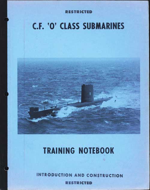
C.F. 'O' Class Submarines, is the first in a series of submarine training manuals for the Canadian Forces Oberon class submarines.
In this online version of the manual we have attempted to keep the flavor of the original layout while taking advantage of the Web's universal accessibility. Different browsers and fonts will cause the text to move, but the text will remain roughly where it is in the original manual. In addition to errors we have attempted to preserve from the original, this text was captured by a combination of optical character recognition and human typist. Each method creates errors that are compounded while encoding for the Web. Please report any typos, or particularly annoying layout issues with the Mail Feedback Form for correction.
The 'O' class submarines are not the first such craft to serve in the R.C.N.
The story of the first R.C.N. submarines is highly colourful. At the outbreak of the First World War, the Government of British Columbia, concerned over the lack of defence on the Pacific Coast, secretly purchased two submarines which were built in Seattle. Independent crews were found, mainly from ex-R.N. officers and men residing in Canada, and on 4 August, 1914 the two submarines were handed over in return for a cheque for $1,150,000. Three days later, the Federal Government ratified the purchase of the submarines which were accepted into the R.C.N. as CC1 and CC2. These two ships remained in service on both East and West Coasts until 1920 when they were paid off to scrap.
Two 'H' class submarines, built in the United States, were given to Canada in 1919 and served in the R.C.N. until 1922. These submarines were two of the many of this class that were built both in Canada and the United States during the First World War. In 1914 a Contract to an American Shipyard had been let for the construction of 'H' class submarines; at the outbreak of war, the neutrality of the United States prevented the submarines being built in that country, so, construction was sub-contracted to Canadian Vickers in Montreal.
There was no further Canadian submarine activity until 1945 when two German U-boats, which had surrendered to R.C.N. ships, were commissioned for trials and evaluation purposes. These were the U 190 and U 889; the former was in use until 1947 when she was sunk in local areas; the latter, U 889, was turned over to the U.S.N.
In 1961, the USS BURRFISH, was turned over to and commissioned into the RCN as HMCS GRILSE. Her purpose to provide target facilities for ASW units on the Pacific Coast.
1-4
1.02 PURCHASE OF THE 'O' CLASS
The Minister of National Defence approved the acquisition of three Royal Navy Oberon class submarines on 11 April, 1962. Following negotiations with the Royal Navy, Treasury Board approval was acquired in December, 1963 and the construction contract was given H.M. Dockyard, Chatham.
Commissioning dates of the submarines, designated 'O' Class Submarines in Canada were:
HMCS OJIBWA
23 September, 1965
HMCS ONONDAGA
22 June, 1967
HMCS OKANAGAN
22 June, 1968
1.03 INTRODUCTION TO THE 'O' CLASS SUBMARINE
The 'O' class submarines have retained the traditional pressure hull configuration rather than the improved hydrodynamic form of the U.S.N. 'ALBACORE' type. The 'O' class has been designed primarily as an ASW vehicle. Particular emphasis has been placed on quiet operations at various depths and speeds.
The basic 'O' class was commenced in 1956 and since that time over 100 design improvements have been incorporated In the submarines.
1.04 DIMENSIONS
Length
295 feet
Beam
26 1/2 feet
Draught
19.1 feet
Displacement (Surface)
2057 tons - 3&5 MBT empty
2196 tons - 3&5 MBT full
(Dived)
2417 tons
Fuel Capacity
104,223 Imp. Gals.
Complement
7 officers 55 men (Ojibwa 58 men)
2-1
C.F. 'O' CLASS SUBMARINES
CHAPTER 2 - CONSTRUCTION, BUOYANCY AND STABILITY
PART I - BUOYANCY AND STABILITY
2.11 INTRODUCTION
The submarine is a ship that is built to operate chiefly below the surface of the water. It must also be adapted to operate on the surface. To be able to perform in both of these mediums the submarine must possess
unusual features of construction.
The first of these features is the possession of ballast tanks and the means to take on or eject ballast from them. In doing this, the buoyancy of the ship is adjusted to make it capable of operating on the surface or at the depth level desired. The second feature is the proper construction of the hull and tanks, not only to withstand pressures but also to provide for the proper distribution of weights so that the ship will be stable at all operation conditions. The third feature is the inclusion of the proper means to propel and control the submarine as it makes its way through the water.
Other chapters in this book will take up tank construction and the various systems for propulsion and control. To prepare for the study of such material, it is necessary to understand buoyancy and stability and how they are provided for in the submarine.
2.12 BUOYANCY
Buoyancy can be stated as being that quality of a body which enables it to remain on the surface of a liquid. In other words, float. As with any ability, there are degrees of buoyancy; the first two are simply the extremes, POSITIVE and NEGATIVE. By these terms we define bodies that float and bodies that sink relative to the liquid they are placed in. The mid-point or NEUTRAL state is one where the body remains "in suspension" in the liquid, neither floating on the surface nor sinking to the bottom.
ARCHIMEDES' principal states:-
"That a body floating or submerged in a liquid is buoyed up by a force equal to
the weight of liquid displaced".
2-2
2.12 BUOYANCY (CONTD)
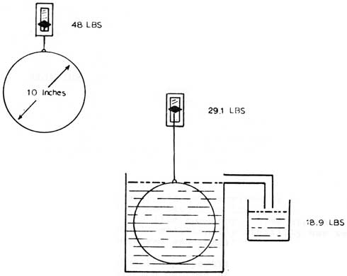
This consideration shows that buoyancy is a factor of displacement rather than one of any other physical property. This fact can be proved by simple experiment:-
A 10 inch sphere of a substance weights 48 lbs. in air, but when fully immersed in water, weighs only 29.1 lbs. A container to catch the water displaced by the sphere will collect 18.9 lbs. of water. The weight loss of the sphere is the same as the weight of the water displaced.
This experiment, as shown in figure 1 can be repeated for identical sized spheres of any weight or substance, and the weight of water displaced remains the same.
(Figure 1)
2-3
2.12 BOUYANCY(CONTD)
It can be seen from the experiment that displacement is dependent upon volume immersed. The sphere in figure 1 when immersed in water weighs more than the water displaced and is therefore NEGATIVE buoyant. If, however, the weight of the sphere were to be reduced without altering its size to such en extent that when immersed it only weighed 10 lbs; then because the resultant weight would be less than that displaced, the sphere would be POSITIVE buoyant. A state of NEUTRAL buoyancy is reached where the weight of an immersed body equals the weight of the displaced liquid.
In summery; the degrees or states of buoyancy are:-
POSITIVE
- Where the weight of the body is LESS than the weight of liquid displaced.
NEUTRAL
- Where the weight of the body is the SAME as the weight of the liquid displaced.
NEGATIVE
- Where the weight of the body is MORE than the weight of liquid displaced.
2.13 STABILITY
Stability in a body can be described as the ability of that body when disturbed to return to its previous condition or position. Stability has, like buoyancy, three states: stable, unstable and neutral; additionally stability has two planes of operation, transverse and longitudinal.
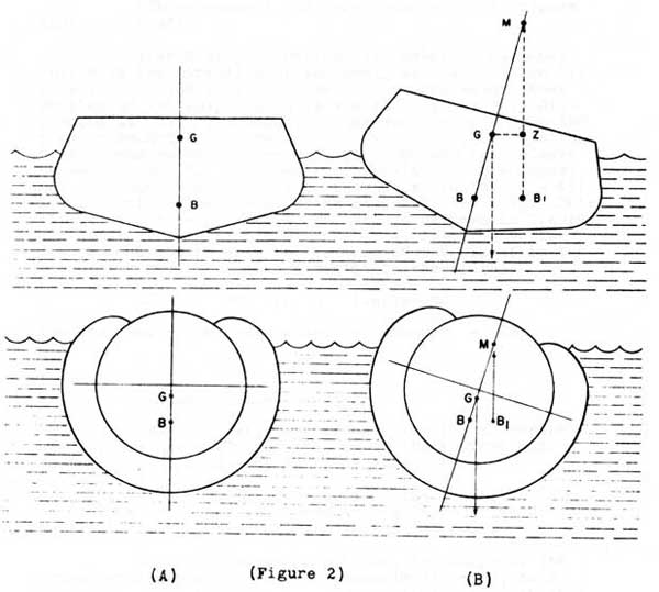
Before explaining the properties of stability in a ship, three terms must be defined and through these as shown in figure 2 the question of stability will he resolved.
2-4
2.13 STABILITY (CONTD)
(Figure 2)
The Center of Buoyancy (B)
- The center of gravity of the displaced liquid (geometric centre of cross-section)
The Center of Gravity (G)
- The effective center of all weights in the ship.
The Metacenter (M)
- The fulcrum of the righting moment for a heeling ship.
2-5
2.14 FACTORS AFFECTING A HEELING SHIP
(These remarks and references refer to figure 2(B) over leaf).
When a ship is heeled its center of buoyancy shifts in the direction of the heel, to new position B1. This fact is due to the change in the underwater cross section of the ship, which is the part of the ship displacing liquid. The amount of movement depends upon the angular amount of the heel and is such that, in relation to the metacenter: a perpendicular through (B1) always passes through M. The center of gravity never changes, but the relationship of it to the perpendicular (M - B1) is proportional to the righting moment of the ship. This distance is referred to as GZ. It can be seen in figure 2(b) that the righting moments are two fold: G acting down and B1 acting up. The fulcrum of the moment is the metacenter and the righting moment is therefore:-
GZ = GM sin θ (angle GMZ)
The ship therefore loses stability when GM = GZ
2.15 STABILITY OF A SUBMARINE
Two different conditions exist for submarine stability, that where the ship is on the surface and that where the submarine is fully submerged.
In the surfaced condition, the stability is similar to any other ship, and the sequence of events mentioned in the previous paragraph will occur.
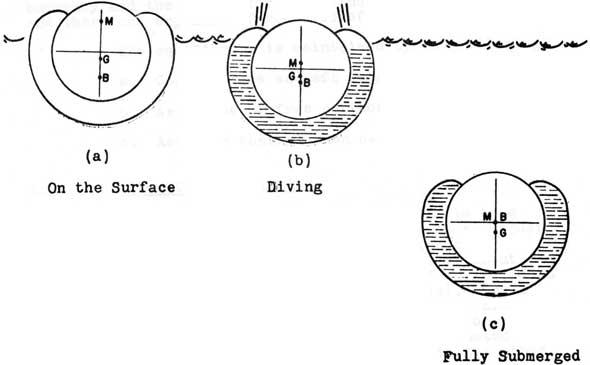
In the submerged condition, the shape of the cross-section has changed, as shown in figure 3, to a cylinder. The physical shape of a cylinder is such that the act of heeling will not change the position of the center of buoyancy. This is true for a submarine, regardless of its underwater shape, as the whole body is immersed.
2-6
2.15 STABILITY OF A SUBMARINE (CONTD)
(Figure 3)
The Change of B and M
When a submarine is dived, the tanks surrounding the actual hull are filled with water, and only the cylindrical pressure hull is effecting buoyancy. In this condition B and M must always remain in the geometric center of the cylinder. (Figure 3(b). Heeling can, therefore only be counteracted by gravitational righting moment.
By comparison of figures 3(a) and (b), the two states of the submarine, it is obvious that a change in the relative positions of G, B and M has to take place during the diving and surfacing operations. It cannot be stated at what time this shift occurs, as the operation is done quickly, the only factor of concern is that of momentary instability, which can under some conditions cause the submarine to heel.
2-7
2.16 LONGITUDINAL STABILITY
So far all remarks have concerned transverse stability. On the surface a submarines longitudinal stability is great, far greater than the surfaces transverse stability. However, on diving again, the center of buoyancy and the metacenter (longitudinal) are coincident; and therefore any minor force will effect the stability.
The equilibrium is maintained by the following:
a. Correct fore and aft weight distribution
b. Avoidance of free surface effect
c. Accurate control when dived
2.17 BUOYANCY AND TRIMMING
Fore and Aft Balance. When the S/M is in a state of neutral buoyancy, the weights must be so adjusted that it remains level. If one end is heavier than the other then that end will cause the submarine to pivot about its centre like a seesaw. These angles "bow up" or "bow down" are indicated by inclinometers (spirit levels). Small in accuracies in the fore and aft balance can be overcome by the use of the hydroplanes, the effect of which, increases with the increase of speed. Balance can be adjusted by pumping water from one end of the submarine to the other via the Trim System.
Change in Total Weight is caused by the loading of stores, torpedoes, oil fuel, fresh water, etc. The components of this change are worked out balanced against a 'standard' trim which is already known before the submarine goes to sea. Differences are compensated for by pumping water out of or flooding into the Trim and Compensating tanks. Any discrepancy that may have occurred while working out and putting on the trim will be noticed when the submarine first dives. The Trimming Officer will then correct the discrepancy by making adjustments with water in the internal tanks. This is called 'CATCHING A TRIM'.
2-8
C.F. 'O' CLASS SUBMARINES
CHAPTER 2 - BUOYANCY, STABILITY AND CONSTRUCTION
PART II - CONSTRUCTION
2.21 HULL SHAPE AND STRENGTH
The ideal shape to withstand pressure is spherical, because the crushing strain caused by sea pressure is evenly distributed. However, the best practical shape from a design and building point of view is CYLINDRICAL with DOMED ends, called a PRESSURE HULL.
2.22 PRESSURE HULL CONSTRUCTION
The hull is prefabricated and built in sections, each section being completed with its superstructure, box-shaped keel and external hull to form a sub-assembly. The sections are transported to position on the launching berth and finally welded to each other to form a complete hull. The pressure hull is of all-welded construction, steel plating, Q.T. 28 is used and is welded to transverse Tee bar frames of the same material, spaced generally 30 in. apart.
Amidships, it is a true cylindrical section with an internal diameter of 17 ft. 9 in. and length of 162 ft. 3 in. extending between frames 25-92.
It tapers at each end to form cones which are not symmetrical about a central axis, but are so constructed that, except for the extreme after end, the top of the pressure hull is horizontal and forms the datum line.
To give maximum strength, each end of the pressure hull is closed by a domed-shaped bulkhead of "B" quality steel approximately 1 1/8 in. in thickness aft, and 1 3/8 forward.
The forward conical section occupies space between frames 18-25 and extends for a distance of 18 ft. 0 in., its internal diameter diminishing from 17 ft. 9 in. to 13 ft. 4 1/2 in. The domed end of this section is pierced to accommodate the torpedo tubes.
2-9
2.22 PRESSURE HULL CONSTRUCTION (CONTD)
Towards the stern the pressure hull tapers from an internal diameter 17 ft. 9 in. to 17 ft. 0 in. (between frames 92-103) in a distance of 25 ft. 0 in. and then further diminishes in diameter from 17 ft. 0 in. to 9 ft. 0 in. in a length of 35 ft. 9 in., embracing frames 103-116. The countermeasure tubes pierce the domed bulkhead and extend through the aftermost end of the hull, which also carries two stablising fins and a stern fin, which latter provides a support for the after hydroplanes, rudder and "A" brackets. To accommodate the propeller shafting where it passes outboard, the pressure hull plating in the vicinity is inbossed and outbossed to form stern tubes. The propeller shafting is arranged with a horizontal rake diverging equally on each side of the ship's centre line, the shafting centres at frame 96 being 6 ft. 0 in. apart, and the propeller centres 11 ft. 6 in. apart. Shaft brackets are provided.
To afford access to the interior of the pressure hull and to provide for embarkation of torpedoes and stores, hatchways are cut in the top of the hull plating. Access between the Bridge and the Control Room is by means of a conning tower, consisting of a pressure-tight steel cylinder fitted at top and bottom with water-tight hatches, the cylinder being welded to the top of the pressure hull.
The W.T. bulkheads at frames 34, 49, 77 and 103 are tested on both sides to an initial test pressure of 70 lb/sq. in. and are subjected to a final test pressure of 35 lb/sq.in., with exception of bulkhead 103 which is subjected to a final test pressure on its aft side of 70 lb/sq.in. This compartment is adapted for use as a recompression chamber. The transverse bulkhead at frame 92 is watertight up to a level of 7 ft. 9 in. below the Datum line to prevent local flooding in the Engine Room from reaching electrical equipment in the Motor Room.
2-10
2.23 THE EXTERNAL HULL AND KEEL
The external hull is made of mild steel plating and surrounds the cylindrical pressure hull to form a space of lunate section (between frames 18-100), and is stiffened by internal frames spaced generally 20 in. apart. Both plating and framing are welded to the top of the pressure hull and to the side of the keel, and further stiffened by tubular struts radial to the pressure hull.
The space between the pressure and external hulls is sub-divided by athwartship bulkheads to form Nos. 2, 3, 4, 5 and 6 main ballast tanks (P and S) and Nos. 1, 2, 3 and 4 oil fuel tanks (P and S).
Access to the interior of the main ballast and fuel tanks is by either free flood holes cut in the bottom plating or through manholes provided in the upper part of each tank. Where the tanks occupy space within the keel, inspection manholes are provided in the side of the keel, with portable plates in the bottom of the keel for access to pig-iron ballast stowage.
The external hull plating is faired and extended in a fore-and-aft direction to form free flooding spaces and is merged into the pressure hull plating to give an efficient streamlined hull form. The external hull structure extends in a forward direction and tapers sharply to form a stem incorporating a free-flooding bow section. A ram plate is fitted from the stem to No. 9 bulkhead between the flats above and below the bow torpedo tubes, and bow shutters linked to the torpedo tube muzzle doors are provided to close the tube apertures.
The external structure aft of the pressure hull dome bulkhead (Frame 116) forms No. 7 main ballast tank and a stern free-flooding space which latter houses the rudder crosshead and the after tube guide trunks. A portable plate (3 ft. 2 in. x 1 ft. 9 in.) is provided in the top plating of the stern free-flooding space for unshipping the rudder crosshead.
2-11
2.23 THE EXTERNAL HULL AND KEEL
The keel is of rectangular section and is welded to longitudinal pads along the length of the bottom of the circular pressure hull, the underside of the keel forming a seat for docking and grounding. It contains a quantity of cast iron ballast stowed in the keel and in ballast boxes, one forward and one aft. Also housed within the keel are the Kingstons for Nos. 3 and 5 main ballast tanks and a Kingston for 'Q' tank. A Sonar Recess, and an Echo Sounder Recess are also formed in the keel. Nos. 1, 2, 3 and 4 fuel oil tanks (P and S) and Nos. 3, 4, 5 and 6 main ballast tanks (P and S) extend into and occupy space within the keel. Transverse bulkheads sub-divide the keel into its various tanks and compartments.
'Q' tank forms a part of the keel. It is built up of thicker plating than the remainder of the keel structure.
The Attack and Search periscope wells extend into the keel.
2.24 THE SUPERSTRUCTURE
A glass reinforced plastic superstructure is attached to the top of the pressure hull, the section forward of the forward torpedo hatch being constructed of steel. It extends fore-and-aft to form a narrow deck. Portable plates and hinged doors in the superstructure afford access to the space beneath it. The sides and the deck are perforated to facilitate draining and flooding.
Amidships between frames 57-78 the superstructure
is built upwards to form a streamlined bridge fin, which
houses the conning tower and the various masts and periscopes.
The upper part of the fin is arranged to form a bridge
(25 ft. above the Datum line). Access to the bridge from
the casing is gained by means of a door in the front plating
of the bridge fin. Portable plates are provided in the
decks of the bridge fin to facilitate the shipment of
battery cells down through the conning tower.
The several mast bearings are arranged in upper and lower flats which form an integral part of the structure. On the lower part of the superstructure the bridge fin is provided on each side with a sponson and a handrail.
2-12
2.25 HATCHES
There are two torpedo loading hatches, angled to facilitate the loading of torpedoes. Because of this the 'T' frames in that part of the torpedo compartment are interrupted. Therefore, before proceeding to sea, steel bars called STRONG BACKS are fitted to restore the strength of the pressure hull at these points.
All other hatches are fitted to the pressure hull vertically between the frames: they are as small as possible and reinforced to ensure pressure hull strength. The conning tower is fitted with an upper and lower hatch to give access to the bridge platform which is at the top of the fin.
2.26 MOTION
Motion is obtained by propellers port and starboard driven by large electric motors, the power for these being drawn from large capacity batteries. There are two batteries in separate battery compartments. No. 1 battery is underneath the accommodation space, No. 2 is underneath the control room. Batteries are recharged by two Diesel Generators. These can also be run at periscope depth, the air being supplied from a large intake tube; this is known as 'SNORKELLING'. Separate induction and exhaust masts are fitted for snorkelling.
2.27 CONTROL
Control of the submarine movements is achieved by a rudder for port and starboard movements, and HYDROPLANES (which may be thought of a horizontal rudders) fitted in pairs for'd and aft.
The FOR'D hydroplanes control the DEPTH of the submarine.
The AFTER hydroplanes control the ANGLE of the submarine.
All controls are operated hydraulically with alternate methods of emergency control and are normally operated from the 'One Man Control' consol.
2-13
Large Plate on Separate Page
GENERAL LAYOUT PLATE 1