|
6A1. Introduction. The submarine is provided
with a salvage air system for use in
salvage operations.
The salvage air arrangements provide external
salvage facilities for use by outside
salvage agencies (divers, etc.) as well as internal
facilities for use by the crew of the
submarine or by a diver who succeeds in
entering the vessel.
Figure 6-1 shows in schematic form the
location and relation of the component parts
which comprise the salvage air system.
Two external high-pressure air connections,
located on each side of the conning
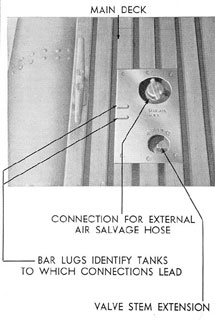
Figure 6-2. Main ballast tank salvage connection.
|
|
tower, provide a means of supplying high-pressure
air from the salvage ship to the high-pressure
(3000-pound) receiving manifold.
This air can be directed by personnel inside
the vessel to the 600-pound blow manifold for
use in blowing the main ballast tanks, and to
the 225-pound service air manifold for use
in blowing water from flooded compartments
by means of the compartment salvage air
valves.
Each main ballast tank has a blow valve
with a blow line connection extending up to
a plate set in the deck (Figure 6-2). In salvaging,
air hose lines from the salvage ship
are attached to the pipe fitting. Opening the
valve enables the rescue vessel to blow the
ballast tanks free of water.
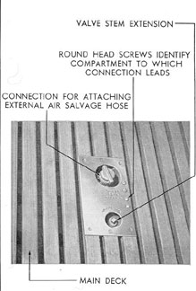
Figure 6-3. Compartment salvage connection.
|
|
6A2. Salvage valves. Each compartment of
the submarine has two salvage valves, one at
each end of the compartment. A salvage line
from each valve extends through the hull to
a deck plate (Figure 6-3), where it is provided
with a capped male fitting similar to those of
the main ballast tank salvage lines (Figure
6-2). The valve (Figure 6-3) can be operated
by a socket wrench from the outside or by
a handwheel from within the compartment.
In salvaging operations, air hoses can be attached
to the valve fittings to supply the ship
with air for breathing, pumping, or circulating purposes.
All the external salvage valve deck plates
are identified by lettering and round screw
|
|
heads and special lugs cast on the plates for
touch identification. (See Section 6C.)
Compartment salvage air valves are
located on each bulkhead between compartments
(Figure 4-1) for use in blowing individual
compartments. The 225-pound air is
supplied to these compartment salvage air
valves by lines extending from the forward
and after ship's service air lines. (See Section
4A.) The arrangement of the valves permits the
release of air from either side of the
bulkhead into the adjacent compartment.
Pressure gages are installed on both sides of
the bulkhead near this valve arrangement to
indicate the pressure in the adjoining compartment.
|
|
6B1. Description. This section describes
those air salvage operations conducted from
within the submarine, either by the vessel's
crew or by a diver who has succeeded in entering
the submarine.
The air which is used can come either
from the ship's air banks or from the salvage
ship by way of the high-pressure air external
charging connections.
The main ballast tanks can be blown from
within the submarine by directing air from
the 3000-pound to the 600-pound MBT blow
manifold and from there to the tanks. The
procedure followed in blowing the main ballast
tanks is the same as outlined in Chapter
3, provided, of course, that none of the blow
lines has been broken or the tanks ruptured.
Each compartment of the vessel is provided
with a compartment salvage air valve,
located high on each transverse bulkhead.
(See Figure 4-1.) Two hundred and twenty-five-pound air is supplied to each valve by
a branch line from the forward or after
service air main, depending upon the location,
as outlined in the previous article.
Each salvage valve is provided with two
outlets and two controlling handwheels. It
|
|
is mounted on the bulkhead with one outlet
and one handwheel on each side of the bulkhead
to permit the blowing of any flooded
compartment from the adjoining compartment.
6B2. Operation. To illustrate the general
procedure to be followed in blowing a flooded
compartment using the compartment salvage
air valves, assume that it is desired to remove
water from the after battery compartment,
working from the control room. In the control
room, the salvage air valve on the after
bulkhead is opened by turning the handwheel
counterclockwise. This admits air into the
after battery compartment. (Clockwise rotation
of this handwheel would admit air into
the control room.) The adjacent pressure
gages will indicate the air pressure in the
battery compartment. When the pressure
necessary to keep the compartment free of
water is indicated, the valve handwheel should
be returned to the neutral position. By building
up an equal pressure in the control room,
the door between the compartments can be
opened without dropping the pressure in the
battery compartment.
Detailed instructions for salvaging flooded
compartments are given in Chapter 11.
|
|
6C1. Description. Each main ballast tank is
provided with a salvage valve and a salvage
line for use in external salvage operations.
Each valve is fitted with a square-ended extension
stem, reaching to the main deck,
where a deck plate (Figure 6-2) is located to
receive it. The receiving end of the salvage
line is fitted with a threaded connection and
a protecting cap with projecting lugs for easy
unscrewing. This connection is fitted in the
same deck plate as the valve stem. The valve
stem is operated by a socket wrench. The
deck plates are located off the centerline.
In use, the air hose from the salvage ship
is connected by a diver to the salvage line and
the salvage valve opened, thus admitting air
to the tank and blowing it free of water. Each
tank must be blown separately.
Each compartment has one salvage valve
and one salvage line located at each end of
the compartment. These valves and lines have
deck fittings similar to those of the main ballast
tanks, but located as near the centerline
as possible. The valve body is located between
the pressure hull and the superstructure deck,
with one end of the stem extending up to the
deck plate (Figure 6-3) and the other end of
the stem projecting through the pressure hull.
The inboard end of the stem is fitted with a
handwheel containing a luminous button.
Thus these valves can be operated from within
the vessel or from the outside.
In each compartment, one valve, termed
the high connection, supplies air near the high
point of the hull. The other valve, termed
|
|
the low connection, is equipped with a pipe
extending to the low point of the compartment.
The low connection pipe is equipped
with a strainer to protect the system from
clogging.
To circulate air from the outside throughout
a given compartment, the, diver must connect
one air hose to the high connection and
another to the low connection. With pressure
applied to the hose connected to the high
connection, its valve is opened, allowing air
to enter the compartment. Opening the low
connection valve allows the air to escape.
When blowing out the compartment, both
the high and low connections are opened.
Compressed air entering the compartment
through the high connection forces the water
into the low-connection pipe and thus overboard.
The external salvage connections for the
main ballast tanks are tested hydrostatically
to a pressure of 15 psi. The external compartment
salvage connections are tested hydrostatically
to a pressure of 300 psi.
All the external hose connections (deck
plates) are identified by lettering; special
markings are provided to enable the diver to
identify the plates by touch. These markings
are lugs, or screws, cast or attached to the
deck plates. The tables on page 40, list the
markings used on a typical submarine. The
actual arrangement of the markings for any
individual submarine is shown on the vessel's
air salvage system plans.
|
