5A1. Introduction. The 10-pound MBT
blowing system is used to remove water from
the main, ballast tanks when the boat is on the
surface. It completes the work started by the
600-pound MBT blowing system, thus saving
high-pressure air.
The 10-pound MBT system (see Figure
5-1) consists of a low-pressure blower located
in the pump room, a manifold, and blow lines
to each of the tanks serviced by the system.
The low-pressure blower furnishes compressed
air to the manifold in the control room
at a pressure of approximately 10 psi. The
manifold distributes the air supplied by the
blower to the ballast tanks, through nine pipe
lines which pass through the hull directly
above the manifold and extend outside the
pressure hull under the superstructure deck.
The air supply to the manifold is controlled
by the flapper valve. The manifold
and the valves are designed to withstand sea
pressure if any of the blow lines fails.
The nine low-pressure lines have lever-operated
flapper valves (10-pound blow
valves) at the point where they pass through
the hull, and swing check valves where they
join the main ballast tank (MBT) vent lines.
Gate valves, controlled from the superstructure
deck, are installed in the lines leading
to main ballast tanks 2A, 2B, 2C, 2D, 6A,
6B, 6C, and 6D.
Detailed operating instructions for blowing
the main ballast tanks, using the 10-pound
system, are given in Chapter 10.
B. THE 10-POUND MAIN BALLAST TANK BLOW MANIFOLD
5B1. Description. The 10-pound blow manifold,
located on the starboard side of the control
room (Figure 5-1.), serves as a center
from which the compressed air supplied by
the low-pressure blow is directed to the
ballast tanks. The piping outside the pressure
hull is hydrostatically tested to a
pressure of 300 psi; the system inside
the pressure hull is tested by air for strength
and tightness to a pressure of 15 psi.
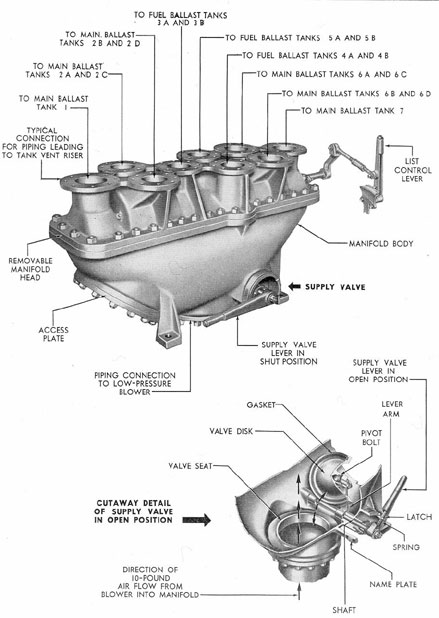
The 10-pound manifold is a boxlike, two-piece
casting. (See Figure 5-2.) The top casting,
or head, is equipped with nine outlet
flanges. It is bolted to the body, or bottom
half, of the manifold. The bottom half has
an inlet port provided with a flapper valve to
admit or shut off the air supply from the
blower. The access plate on the bottom forward
part of the manifold permits inspection
or repair.
The flapper valve is opened by lifting the
flapper valve lever which is connected to the
shaft. Movement of the shaft attached to the
lever arm causes the valve to be unseated, and
air from the blower enters the manifold to be
distributed to the ballast tanks.
The 10-pound manifold is also equipped
with two list control dampers, one for each
Y-valve, operating on a shaft that runs fore
and aft through the head. The dampers are
opened and shut by the list control lever
located on the after end of the head. (See
Section 5E.) The list control dampers are
used to correct unequal blowing of the tanks
which might cause listing of the boat.
When it is desired to blow the main ballast
tanks with the 10-pound MBT blowing
system, the 10-pound manifold supply flapper
valve is opened by lifting the supply flapper
valve lever. With the valve open, the air
from the blower passes into the manifold
chamber. From there, in accordance with the
number of 10-pound blow valves opened in the
blow lines above the manifold, the air is
29
Figure 5-2. The 10-pound main ballast tank blow manifold.
30
directed to the main ballast tanks. The fuel
oil ballast tanks have the same piping and connections
as the main ballast tanks and
therefore can be blown by the 10-pound blowing
system when they are used as main ballast
tanks.
C. LOW-PRESSURE BLOWER
5C1. Description. The low-pressure blower
supplies compressed air for blowing the main
ballast tanks after the boat has surfaced. As
the submarine surfaces, the outside air is admitted
to its interior. This provides a continuous supply
of air to the low-pressure blower,
and conserves the supply of compressed air in
the ship's air banks. The blower is mounted
on the starboard side of the pump room with
the electrical controls in the control room.
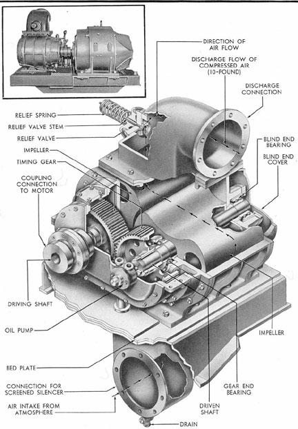
The low-pressure blower is of the rotary,
positive displacement, Roots type. It is
powered by a 90-hp motor, connected by means
of a flexible coupling to the blower driving
shaft.
The mechanical construction of the
blower is shown in Figure 5-3.
Two lobe-shaped impellers divide the
case into two chambers, the upper and lower.
The impellers are connected to steel shafts,
and rotate with just enough clearance to
avoid contact with the casing and with each
other. Gears keyed to the shafts maintain the
proper relation between the two impellers.
A double row of contact bearings at the ends
of the shafts farthest from the gears, together
with a bearing carrier, positively secure
the shaft and the impellers axially, thus
preventing possible friction between the ends
of the impellers and the head plates.
As the impellers rotate, more space is
made available in the lower chamber, causing
suction, and less space becomes available in
the upper chamber, causing compression. The
suction of the blower draws air from the
boat's atmosphere, through the screened silencer
attached to the air intake, and into the
lower impeller chamber. The air thus admitted
is forced by impeller action to pass
into the upper chamber, where it is compressed,
and finally expelled through the discharge
connection which is connected by
piping, extending through the platform deck
to the 10-pound blow manifold in the control
room.
Should the volume of compressed air be
excessive, or should the discharge valve be
closed while the blower is in operation, a
spring-loaded relief valve at the entrance to
the discharge connection operates automatically
to relieve the pressure.
D. THE 10-POUND BLOW (FLAPPER) VALVE
5D1. Description. The 10-pound blow valves
direct the flow of air from the 10-pound manifold
to the main ballast tanks, and to the
fuel ballast tanks when desired. There are
nine such manually operated valves, one on
each of the blow lines extending from the 10-pound
MBT blow manifold, at the point
where the lines pass through the inner hull
on the starboard side of the control room.
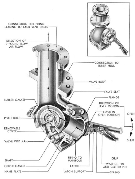
The mechanical construction of a 10-pound
blow valve is shown in Figure 5-4. Each
10-pound blow valve has a lever grip and
spring latch connected to a shaft which is
supported by the valve body near the valve
seat. A lever arm mounted on the other end
of the shaft is connected to the valve disk
by a pivot bolt and socket which enable the
disk to adjust itself to the valve seat, thus
assuring an airtight fit. When the lever is
pulled down, the valve disk is raised and the
valve is shut. When the grip is released and
the lever is pushed up, the valve is opened
and air flows from the manifold to the tank
vent risers. A heavy rubber gasket ring on the
disk forms an airtight contact surface. A
notched quadrant holds the latch, the lever,
and the valve disk in a set position. On the
quadrant, a name plate marked OPEN and
SHUT indicates the position of the valve.
The discharge end of the valve body extends
through the inner hull, to which it is
bolted at the intermediate flange, to form a
watertight joint. The flanged end of the valve
outside the hull is connected by piping to
31
Figure 5-3. Low-pressure blower.
32
Figure 5-4. The 10-pound blow (flapper) valve.
33
the tank vent riser. The flanged end inside
the hull is connected to the 10-pound blow
manifold.
5D2. Location of 10-pound blow valve. The
following table lists, from forward aft, the
nine 10-pound blow valves in the order in
which they are installed on the overhead.
Figure 5-2 shows the connection to the manifold.
1. Main ballast tank No. 1
2. Main ballast tanks No. 2B and 2D
3. Main-ballast tanks No. 2A and 2C
4. Fuel ballast tanks No. 3A and 3B
5. Fuel ballast tanks No. 4A and 4B
6. Fuel ballast tanks No. 5A and 5B
7. Main ballast tanks No. 6B and 6D
8. Main ballast tanks No. 6A and 6C
9. Main ballast tank No. 7
E. LIST CONTROL DAMPERS
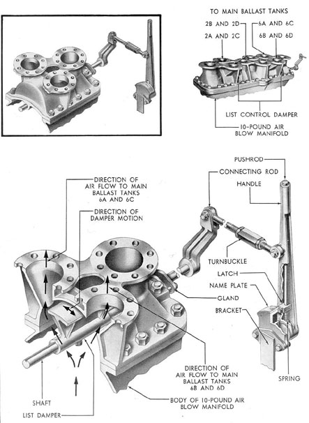
5E1. Description. The list control dampers
are used to correct a list during the blowing
of the main ballast tanks. The list control
dampers adjust the amount of air admitted
into the port or starboard ballast tanks of the
No. 2 and No. 6 MBT group, increasing or decreasing
the rate at which the tank is blown.
The dampers are located at the Y-valve outlet
connections on the 10-pound blow manifold
(See Section 5B).
Figure 5-5 shows the construction of the
damper. Both list dampers are attached to a
shaft that runs through the manifold chamber.
The shaft is operated by a hand lever at the
after end of the manifold. The handle assembly
consists of a push rod at the top of the
handle, a handle, a spring, a latch, a name
plate, and a bracket. A connecting rod attached
to the handle is equipped with a
turnbuckle secured with a bolt and nut. Pressing
down the pushrod releases the spring, lifting
the latch, and leaving the lever free to move
inboard or outboard. As the shaft turns, the
list dampers are swung to shut one port, or
open both ports of the Y.
The movement of the lever and the attached
connecting rod turns the shaft by
means of an offset arm. Outboard movement
of the lever causes the damper to restrict the
flow of air to the starboard side. Inboard
movement of the lever causes the damper to
restrict the flow of air to the port side. Normal
position of the damper is neutral, allowing
equal flow to both sides.
List control dampers control the flow of
air to main ballast tanks 2B and 2D, 6B and
6D on the port side, and to main ballast tanks
2A and 2C, 6A and 6C on the starboard side.
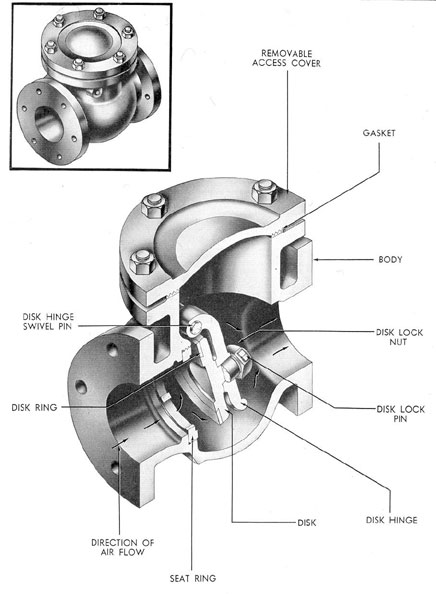
F. THE 10-POUND BLOWING SYSTEM SWING CHECK VALVE
5F1. Description. A swing check valve is
located in the piping at the entrance to each
main and fuel ballast tank, outside the pressure
hull and under the superstructure deck.
It prevents air from backing up from the tank
into the lines of the 10-pound blowing system.
Figure 5-6 is an illustration of a typical
swing check valve. The valve has a swinging
disk mounted on a hinge attached within the
valve body. The valve opens when the flow
of air to the tank forces the disk away from
the seat, and shuts when the flow of air in
the opposite direction forces the disk against
the seat. This prevents a backflow of air into
the lines. A hinge pin supports both the hinge
and the disk, permitting the swinging motion.
A lock nut and pin fasten the hinge and disk
together. The disk and seat ring are removable
for regrinding. A removable cap on top
of the valve allows servicing of the working
parts. A gasket between the cap and the valve
body prevents leakage.
34
Figure 5-5. List control damper.
35
Figure 5-6. The 10-pound blowing system swing check valve.