Submarine Qualification Book - Mark 37 Torpedo, 1966 is a section of an officers qualification book describing the tactics used with an early version of this electric Cold War homing torpedo.
Pages 2-6 through 2-28 are missing from the original.
In this online version of the manual we have
attempted to keep the flavor of the original layout while taking advantage
of the Web's universal accessibility. Different browsers and fonts will cause
the text to move, but the text will remain roughly where it is in the original
manual. In addition to errors we have attempted to preserve from the original
this text was captured by optical character recognition. This process creates errors that are compounded while encoding for the Web.
We thank USS Pampanito and Bill Parker for the generous loan of the original document used to create this online version.
Please report any typos, or particularly annoying layout issues with the Mail Feedback Form for correction.
INTRODUCTION: The MK 37-0 Tactical Doctrine has been developed by COMSUBDEVGRU TWO and promulgated by COMSUBLANT and COMSUBPAC for use by the operating forces. It is subjected to constant scrutiny and, when applicable, revision by the Development Group. The following pages have been extracted from the latest revision to the MK 37-0 Tactical Doctrine for use in the Tactics curriculum at the Submarine School. Omissions from the complete doctrine include only the laborous and detailed instructions for the use of the Deflection Angle Curves and certain diagrams which could be confusing to the novice. Omitted sections shall be explained in the classroom.
101. In order to place the MK 37-0 torpedo in a position from which it will be able to acquire any given target, careful consideration must be given to the selection of the following:
a. Non-synchronous settings.
b. Running depth and enabling distance.
c. Gyro angle.
d. The number of torpedoes to be fired.
102. Selection of non-synchronous settings, Running Depth and Enabling Distance should be dictated by the target's present or predicted conditions and environmental conditions. Selection of Gyro Angle and number of torpedoes to fire is generally dictated by the degree of accuracy of prediction of the target's future position and motion.
103. During the time that elapses between the detection of target, and the launching of each torpedo, selection of settings for each torpedo must be made. If this time is short these selections have to be made, either by assuming certain target conditions and making selections based on these, or by covering probable conditions of the target. Where, however there is a reasonable period of time during which the target is being tracked, optimum selections of torpedo settings may be made. The objective of this section is to show what these optimum selections are.
SELECTION OF NON-SYNCHRONOUS SETTINGS
(article numbers refer to articles in Volume II of the MK 37-0 Tactical Doctrine)
a. High Speed in the Passive Mode should be used under the following conditions:
(1) Against a clearly cavitating target. and
(2) Where sonar conditions are good. and
(3) Where torpedo run is not greater than 10,000 yards.
b. Low Speed in the Passive Mode should be used under the following conditions:
(1) Against a marginally cavitating target. or
(2) Where sonar conditions are poor. or
(3) Where torpedo run is over 10,000 yards.
c. High Speed in the Active Mode should be used under the following conditions:
(1) Non-cavitating target. and
(2) Where torpedo run is not greater than 10,000 yards.
d. LOW Speed in the Active Mode should be used only where the following conditions exist:
(1) Noncavitating target. and
(2) Torpedo run is in excess of 10,000 yards.
1-3
e. Low to High Speed, setting produces the same Panel Sensitivity as the High Speed setting. Little tactical advantage is achieved through selection of this setting. As designed this setting allows the torpedo speed to shift from Low to High after the torpedo establishes close-in.
f. In general, High Speed should be used on all targets within high speed run of the weapons, Low Speed should be used only to obtain the greater range of the low speed run of the weapon, and the Active Mode should be used if in doubt of sufficient 60 kc noise being produced by the target. Theme is an increase in sensitivity of 6 db when the torpedo is set in Low Speed-Passive. This and only this combination will cause this increase in sensitivity. Consequently, if Active is selected there is no advantage in using Low Speed when the target is within 10,000 yards. If Passive is selected, some consideration might be given to using Low Speed' when the target is within 5,000 yards. The disadvantage here of course, is the increase in time of the torpedo run thus permitting the target more time to evade or shutdown. If the target is making speeds in excess of 12 knots then High Speed must be selected.
106. Horizontal Search: Snake, Circle Right, Circle Left (Art. C.05)
a. Unless the future position of the target can be predicted to an accuracy of ± 500 yards SNAKE Search should always be used. The deflection angle curves/spread plotters are based on the torpedo being set in SNAKE Search.
b. Where the position of the target can be predicted to an accuracy of ± 500 yards, CIRCLE Search may be used. The direction of Search (Right or Left) should be in the same direction as target motion.
c. The torpedo when set in CIRCLE Search will snake for 1000 yards after the torpedo enables before it will start to circle.
107. Stratum: Above Limits, Below Limits, No Limits. (Art. C.06)
a. If the target depth is known to be wholly above 100 feet. Set ABOVE LIMITS.
b. If the target depth is known to be wholly below 100 feet. Set BELOW LIMITS.
1-4
c. If the target depth is unknown or is estimated to be about 100 feet set NO LIMITS.
108. Depth Search: (This, is not a setting but a procedure which the torpedo will follow if set to CIRCLE Search with a running depth below 150 feet and STRATUM setting of BELOW LIMITS or NO LIMITS. (Art. A.01.7). It may also occur after lost contact regardless of programmed horizontal search.
SELECTION OF SYNCHRONOUS SETTINGS
109. Enabling Run: (Capable of being set from 300 yards to 9,500 yards)
a. Set ENABLING RUN to 600 yards if the following conditions are met. (Art. C.09)
(1) Firing Submarine protected by Stratum Setting.
(2) SNAKE SEARCH is employed.
UNLESS
it is required to enable the torpedo beyond false targets (either natural or artificial i.e. ice or sea state) or beyond the screen when attacking a screened target.
IN WHICH CASE
set enabling run beyond position of false targets or screen but where possible, NOT MORE THAN 50% of estimated torpedo run.
b. Set ENABLING RUN to 600 yards if the following conditions are met.
(1) Firing Submarine is not protected by Stratum Setting.
(2) SNAKE SEARCH is employed.
(3) Torpedo set to PASSIVE Homing.
(4) Firing Submarine is quiet.
c. Set ENABLING RUN to 2,000 yds - but NOT MORE THAN 50% of estimated torpedo run if the following conditions are met.
(1) Firing Submarine is not protected by Stratum. Setting.
1-5
(2) SNAKE SEARCH is employed.
(3) Torpedo set to ACTIVE HOMING.
d. DO NOT ATTEMPT TO SET TORPEDO DJ ENABLE "JUST" SHORT OF TARGET. If the target's future position can be predicted with sufficient accuracy to make this procedure possible (i.e., to within ± acquisition range) use CIRCLE SEARCH.
e. Set ENABLING RUN to 1,000 yards LESS THAN torpedo run or set ENABLING OFFSET to 1,000 yards under the fallowing conditions:
A. IN HIGH SPEED, DO NOT SET. RUNNING DEPTH, LESS THAN 60 FEET.
B. IN LOW SPEED, DO NOT SET RUNNING DEPTH LESS THAN 45 FEET.
C. IF ABOVE LIMIT OR BELOW LIMIT IS SET, DO NOT SET RUNNING DEPTH OUT OF STRATUM LIMITS NOR WITHIN 15 FEET OF 100 FEET.
D. DO NOT SET RUNNING, DEPTH THE OPPOSITE SIDE OF A THERMAL LAYER FROM THE TARGET.
E. IN SHALLOW WATER, DO NOT SET RUNNING DEPTH WITHIN 70 FEET OF THE BOTTOM, WHEN ACTIVE HOMING IS EMPLOYED.
IF TARGET DEPTH IS KNOWN
a. Set. Running Depth at. Target Depth if:
1-6
(1) Isothermal water conditions exist above the target depth or
(2) Torpedo set to ACTIVE HOMING.
b. Set RUNNING DEPTH 100 feet below target depth if:
(1) A negative thermal gradient exists from Target Depth and below. and
(2) Torpedo set to PASSIVE HOMING.
c. See RUNNING DEPTH 100 feet above Target Depth if:
(1) A Positive Thermal gradient exists from Target Depth and above. and
(2) Torpedo set to PASSIVE HOMING.
IF TARGET DEPTH IS NOT KNOWN
a. In general, the torpedo will acquire a target whose keel depth is 200 feet different from the torpedo's running depth, under isothermal water conditions. One torpedo will thus cover 400 feet in depth.
b. Against a nuclear submarine-fire two torpedoes in a depth spread.
(1) 1 set at 400 feet.
(2) 1 set at 750 feet.
c. Against a conventional submarine on the battery, fire two torpedoes in a depth spread.
(1) 1 set at 200 feet.
(2) 1 set at 550 feet.
d. In Shallow water and when firing against any target
1-7
if the water is isothermal fire:
(1) 1 set at 100'
This torpedo will provide adequate depth coverage since shallow water is defined as water less than 300 feet deep.
e. Torpedoes fired to cover errors in depth estimation must be fired as duplicates of torpedoes spread in azimuth. Torpedoes spread in depth are as susceptible to mutual interference as those spread in azimuth. Therefore the same interval is necessary between units of a salvo whether the salvo is spread in depth or in azimuth. (See article 112)
111. Torpedo Settings Chart. A summary of the recommended torpedo settings is contained in tabular form in the Torpedo Settings Chart on page 1-10. By entering the chart with the known or the best estimated conditions of the target, of own submarine, and of the environment, the recommended non-synchronous and synchronous torpedo settings may be obtained, This chart should be readily available to the approach officer and the assistant approach officer at all times during the prelaunch phase of the torpedo approach and attack. A thorough understanding of the capabilities and limitations of the MK 37 torpedo is necessary for the effective use of this chart.
112. Firing Internal.
112.1 The MK 37-0 torpedo is Susceptible to mutual interference between
units of a salvo if the units are not fired with sufficient time interval between the units. This interval is required whether separated in azimuth or in depth,
1-8
112.2 The required firing interval necessary to prevent mutual interference between units of a Passive Salvo is 15 seconds.
112.3 The required firing interval necessary to prevent mutual interference between units of an Active Salvo is two minutes and 15 seconds.
113 Switch Tolerances
113.1 The Weapons Department, SUBASE, NLON has published information listed below on various switches with the operating tolerances 0 of each. When establishing the running depth to be plated on a unit one must consider those tolerances.
EXERCISE CEILING SWITCH (ADJUSTABLE)
PART NUMBER
RANGES
OPERATING PRESSURE
MAXIMUM OVERLOAD PRESSURE
TOLERANCE
1154794
0-225'
0- 100 lbs
600 lbs
3 lbs or 7'
1155531
225'-450'
100-200 lbs
600 lbs
6 lbs ox 14'
DEPTH CUTOUT SWITCH (NON-ADJUSTABLE)
PART NUMBER
OPERATING DEPTH
MAXIMUM PRESSURE
OPERATING TOLERANCE
815780
150'
550 lbs
67 ± 3.25 lbs or 152' ± 7 1/2'
815790
315'
550 lbs
140 ± 7 lbs or 318' ± 15 1/2'
815506
450'
550 lbs
200 ± 10 lbs or 455' ± 23'
815779
1000'
550 lbs
450 ± 22 1/2 lbs or 1022' ± 51'
STRATUM SWITCH (NON-ADJUSTABLE)
PART NUMBER
OPERATING DEPTH
MAXIMUM PRESSURE
OPERATING TOLERANCE
859916
100'
44.4 ± 1.8 lbs (decreasing) or 100' ± 4'
-
44.4 ± 4.4 lbs (increasing) or 100' ± 10'
ANTI-BROACH
PART NUMBER
OPERATING DEPTH
MAXIMUM PRESSURE
OPERATING TOLERANCE
858508
4'
350 lbs
2 ± .2 lbs decreasing or 4 1/2' ± 1/2' 2 ± .9 lbs increasing or 4 1/2' ± 2'
2-1
SECTION 2
DETERMINATION OF GYRO (DEFLECTION) ANGLE
201 General
201.1 This section is concerned with the determination - and applications - of optimum settings for the torpedo gyro angle, This viii be treated in two parts: (1) the derivation of optimum deflection angle(s) and (2) aiming the torpedo(es) by setting proper gyro angle(s) (i.e. corresponding to the optimum deflection angles). There are two methods which may be used to determine optimum deflection angles. These are:
(1) The Deflection Angle Curves
(2) The MK 37-0 Spread Plotters
201.2 The derivation of deflection angle(s) is a process which can and should commence when the target true bearing and direction of drift are established. In the usual approach the selection of optimum deflection angle(s) is refined by additional information concerning target position and motion. Hence, optimum deflection angles should be continuously available for insertion into the torpedo. If and when the commanding officer chooses, the deflection angle can be readily, inserted into the TDC* or other gyro angle computing/setting device. Thus each torpedo can be aimed so as to have the greatest probability of acquiring and hitting the target.
* TDC is used in a generic sense in this section
201.3 The primary fire control method presented herein encompasses shooting (sequentially) a salvo of torpedoes, spread, as necessary, horizontally (in azimuth) and vertically (is depth) and utilizing the snake mode. Individual units are aimed using deflection angles obtained graphically from the Deflection Angle Curves or the Spread Plotters. The use of Circle Search is not recommended, except in very special circumstances, and no, petition of its use is made in this section (see C.05 for discussion on this point).
202 DEFLECTION ANGLE CURVES
202.1 A complete set of Deflection Angle Curves is provided as an enclosure to this publication. (NOT TO STUDENTS)
2-2
202.2 Each set consists of (10) sheets:
Target Speed (kts)
Target Range (kyds)
Target (True) Bearing Rate °/min
(6) High Speed Torpedo Curves
3,6,9,12,15,20
2,3,4,6,10
.5 to max possible, (in 1/2° steps where feasible)
(4) Low Speed Torpedo Curves
3,6,9,12
2,3,4,6,20
.5 to max possible, (in 1/2° steps where feasible
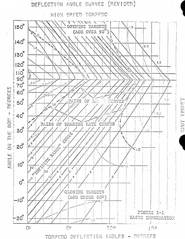
202.3 Each sheet provides for the following target aspects:
Closing Target - AOB 0° to 90° and who may zig so as to show AOB on the other bow of up to 50°
Opening Target - AOB 90° to 180°
Figure 2-1 is a section of a typical sheet: 3 kts target, high speed torpedo.
202.4 There is a wealth of information provided on each sheet of the curves as can be seen by studying Figure 2-2. (Not to students)
202.5 These Deflection Angle Curves are cast in a form suitable for graphical, determination of deflection angles where boundary or limiting conditions only need be set for the various target parameters. If, in special circumstances, exact values are presumed to be known then these limits narrow to the value of that particular parameter. The deflection angle obtained at the intersection of the "C" line (the infinite range line) and "AOB" line when the parameters speed and angle on the bow are accurately known is the same as that computed by the TDC. Since the parameter Speed, angle on the bow, range, and bearing rate are normally not known, the deflection angle curves have been computed and drawn to take advantage of the acoustic path of the ocean swept by the Mark 37 torpedo. For each firing an optimum deflection angle/angles between an upper limit and a lower limit which is/are dependent upon the parameters can be selected. It must be emphasized that assurance of target acquisition is provided only if the actual values of target parameters do in fact lie between the stipulated limits.
203 DERIVATION OF DEFLECTION ANGLE - to be covered in class
2-3
Figure 2-19
2-5
210 USE OF THE MK 37-0 TORPEDO "WET-HEN" SPREAD PLOTTERS
210.1 Introduction - there exists several objections to the use of the conventional deflection angle curves:
(1) The DA curves are difficult to handle in the confined spaces of the attack center.
(2) The target's parameters are difficult to plot as areas of interest when the target's speed is high, and especially difficult when OB is also high.
(3) Many individuals who are responsible for using the curves are slow in obtaining a DA due to the complexity of the curves. Proficiency is obtained only through constant use.
The MK 37-0 Spread Plotters have been developed to overcome the above difficulties. Deflection angles and range coverage found by use of the plotters agree with equivalent solutions obtained from the conventional deflection angle curves.
Three MK 37-0 Spread Plotters are needed; one for use with the high speed unit, and two for use with the low speed unit. Two plotters are necessary for the own speed unit because of its long torpedo run capability. One spread plotter for the low speed unit covers targets from a range of 0-10,000 yards. The other spread plotter for the low speed unit covers targets from a range of 0-23,500 yards.
NOTE: Target Bearing rate as used in section 211 and 212 always refers to True Target Bearing Rate.
The Spread Plotters as designed can be used for opening or closing targets. The procedure for each is the same.
In order to demonstrate proper and efficient usage of the spread plotter, three "type problems" will be formulated and solved using the MK 37-0 plotter (high speed). Use of the Low Speed Plotters is similar.
(1) Type problem I - both bearing rate and target range are known accurately;
(2) Type problem II - the bearing rate is known accurately but the target range is known only within specified limits; and
(3) Type problem III - the bearing rate and target range are known only within specified limits.
2-29
211 DESCRIPTION OF THE PLOTTERS
211.1 The plotting board has three scales:
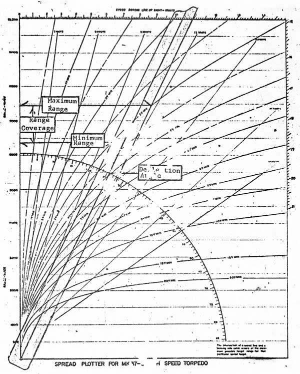
a. A range scale (in yards) arranged vertically along the left edge on which is read range to target, maximum range covered, minimum range covered, and total range covered (see Figure 2.19). The range is scaled at 500 yards per inch.
b. An angular scale (in degrees) on which is read deflection angle. (See Figure 2-16)
c. A linear scale across the top of the plot indicating speed across the line of sight. For each deflection angle there is always a related speed across the line of sight since:
Sin DA = Speed across the line of sight / Torpedo speed
The value of Speed-across-the-line-of-sight as read directly under the cursor of the plastic arm can be used in setting the deflection angle into the torpedo and will be explained in a later section.
211.2 The plot, itself, is composed of two sets of parametric curves:
a. Target bearing rate curves labeled in degrees/minute. These curves are constructed using a 400 yard laminar point for the MK 37-0 torpedo.
b. Maximum target speed lines labeled for various maximum target speeds (in knots).
211.3 A plotter arm of transparent plastic (see Figure 1-17) is pivoted at the lower left corner of the plotting board. The arm is 1.2 inches wide, which represents a swept path of 600 yards in width and has a scribed line down its center. The deflection angle reading is taken at this scribed line on the deflection angle scale. The width of the plotter arm is important in determining range coverage, as will be described later. Since the torpedo has a 14° acquisition cone and snakes 30° either side of set torpedo course, the torpedo will sweep an arc of 74° at a range of 500 yards. This results in a path 600 yards wide. If the acquisition range is different than the assumed 500 yards, the width of the cursor must be changed proportionally.
212 VARIABLES FOR ENTERING PLOTTER
212.1 The variables for entering the plotter are: (a) Target bearing rate (degrees/minute), and (b) Target range (in yards) must be known or estimated within specified limits in order to use the Plotter.
If the speed lines are to be used, it is also necessary to have an estimate of the maximum target speed (in knots). If a target speed estimation, is used, the plotter should be entered with the upper limit of target speed.
2-30
212.2 General Remarks on Solutions - Interpolation may be conveniently accomplished by sketching on the plastic face of the plotter with a grease pencil.
Throughout the following explanations, all numerical results will be taken from the accompanying figures.
212.3 Solution of Type Problem I - For this type problem the bearing rate and target range are both known accurately. The plotter arm is set so that the centerline intersects the appropriate bearing rate curve at the known range. The deflection angle can then be read directly. (For example, in Figure 2-16, the known conditions are a bearing rate of 3 degrees/minute, and a target range of 7,000 yards. The proper deflection angle is immediately read as 25.6 degrees)
Range coverage for a torpedo fired at a given deflection angle against a target of known bearing rate can be quickly evaluated by use of the spread plotter. The intersection of the right edge of the plotter arm and the bearing rate curve in use occurs at the maximum range covered by a torpedo fired under the given conditions (see Figure 2-16). Likewise, the intersection of the left edge of the plotter arm and the bearing rate curve indicate the minimum range covered by a torpedo fired under the given conditions. It is clear that the range bracket between the values found above is covered by the torpedo fired under the given conditions. (For example, in Figure 2-16, for a bearing rate of 3 degrees/minute at a target range of 7,000 yards, the maximum range covered is about 7,480 yards and minimum range covered is about 6,400 yards. The range bracket 6,400 yards to 7,480 yards is covered by firing a unit at a 25.6 degree deflection angle against a target with a bearing rate of 3 degrees/minute)
If the left edge of the plotter arm is tangent to the appropriate bearing rate curve (or to the left of the curve), then the range coverage may be considered to extend from the enabling point to the maximum range as found above. As a matter of practice, it is not necessary to use a deflection angle smaller than that for which the left edge of the plotter arm is tangent to the bearing rate curve in use, since range coverage still begins at the enabling point and the only effect of the smaller deflection angle is to needlessly sacrifice maximum range capability. (For example, in Figure 2-17, the point of tangency between the 3 degrees/minute bearing rate curve and the left edge of the plotter arm occurs at about 2,350 yards. Range coverage then exists from the enabling point to about 5,150 yards. The, minimum deflection angle that need be used against
a 3 degree/minute bearing rate target is about 15.1 degrees)
2-31
Figure 2-16
2-32
Figure 2-17
2-33
212.4 Solution of Type Problem II - For this type problem the bearing rate is known accurately, but the target range is known only between Specified limits. To find the proper deflection angles to cover the target in range the first step is to set the left edge of the plotter arm so that it intersects the proper bearing rate curve at the minimum range which is to be covered (For example, as in Figure 2-18, it is desired to cover a target of 2 degrees/minute bearing rate in range beginning at the enabling point. Therefore, the left edge of the plotter arm is made tangent to the 2 degree/minute bearing rate curve at about 2,650 yards) The deflection angle of the first shot in the spread is recorded. (In the present example, shown in Figure 2-18, the deflection angle of the first shot would be about 12.4 degrees) The maximum range covered by the first shot is noted, as about 6,300 yards.
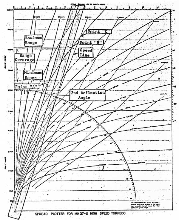
This maximum range for the first unit becomes the minimum range for the second unit in the spread. The simplest method of finding the deflection angle for the second shot in the spread is to note the intersection of the right edge of the plotter arm and the appropriate bearing rate curve for the first unit. (In Figure 2-18, this point is labeled point "A") The plotter arm is moved clockwise until the left edge of the plotter arm cuts through the point found above. (In Figure 2-19, the arm is shown rotated so that the left edge of the plotter arm passes through point "A") The deflection angle for the second shot is recorded. (In the present example the deflection angle for the second shot, as shown in Figure 2-19, is about 17.7 degrees) The new intersection between the right edge of the plotter arm and the proper bearing rate curve is noted. (In Figure 2-19, this point is shown as point "B") The "stepping" process outlined above is repeated as often as necessary to cover the target in range.
To assist in determining the number of torpedoes which must be fired to completely cover the target in range when only the Bearing Rate is known, we find that if an estimate of maximum target speed is made we can determine the maximum range that need be covered in the following manner: Find the intersection of the proper bearing rate curve and the maximum speed line for the target ship. (For example, as shown on Figure 2-19, if the target has a 2 degree/minute bearing rate and a maximum speed of nine knots, then point "C" occurs at the maximum range which need be covered. It is easy to see, therefore, that a spread of three torpedoes will be sufficient against a target making
9 knots or less and showing a 2 degree/minute bearing rate, even if range coverage must commence at the enabling point)
2-34
Figure 2-18
2-35
The intersection of any particular speed line and an appropriate bearing rate curve occurs at the maximum range at which the target of specified speed may show the given bearing rate (i.e. AOB = 90°).
212.5 Solution of Type Problem III - For this type problem the bearing rate and target range are both known only between specified limits. The area of interest is outlined on the plotter with a grease pencil.' (For example, in Figure 2-20, the bearing rate is known to lie between 3 and 4 degrees/minute, and the target range is estimated to be between 5,000 and 7,000 yards. The area of interest is the total cross-hatched area) The procedure in solving this type problem is quite similar to that used in Type Problem II, except that an area of interest must be covered, rather than a line of interest. To insure that the total area is covered, the stepping of the plotter arm must be carried out in relation to the left and upper boundaries of the area of interest. Stepping over the left and upper boundaries actually causes small wedges of the area to be covered twice. It should be noted that use of the right and lower boundaries will cause small wedges of the area to be missed as the plotter arm is stepped across the area of interest. (For example, in Figure 2-20, proper solution of the problem leads to use of points "X", "R", "S" and "T". These points indicate the stepping deflection angles obtained are: 20.8, 25.3, 29.7 and 33.8 degrees respectively)
If an estimate of maximum target speed is available, then the area of interest and consequently the required number of torpedoes in the Spread may be reduced in many cases. (For example in Figure 2-20, if the maximum speed of the target is known to be 12 knots, then the area of interest can be reduced to only the area of double cross-hatching)
Proper solution of problem area of interest leads to use of points "X", "R", "S" and "Q". The deflection angles obtained are: 20.8, 25.3 and 29.7 respectively. Notice that by knowing maximum target speed, it was possible to show that the torpedo fired at a deflection angle 33.8 in the first case would not be necessary.
212.6 Inserting Deflection Angle into the Torpedo.
On the plotter corresponding to each deflection angle can be read a corresponding speed across the line of sight. To set the indicated deflection angle into the torpedo, set a 90' AOB into the TOO, using a starboard angle on the bow for a right deflection and a port angle on the bow for a left deflection angle.
2-37
Figure 2-20
2-38
Set the target speed as the speed across the line of sight which corresponds to the deflection angle determined. Set the torpedo speed at 24 knots. The range to be set into the TDC is the range that coincides with the intersection of the cursor of the plastic arm and the bearing rate curve being used. Figure 2-16 indicates that the 25.6° deflection angle can be obtained by inserting into the TDC 10.4 knots as the target speed and 5500 yards as target range.
When firing the low speed torpedo, the procedure is similar except torpedo speed is set at 15.8 knots. Set range in the same manner as with the high speed torpedo with the following exception. In the MK 106 Fire Control System (Ordalt 4095 completed) the maximum Solution time for the system is 14.4 minutes. This results in a generated solution for only those fire control problems which have a torpedo run of 7500 yards or less. Therefore care must be exercised in setting range when firing the low speed torpedo. If the TDC does not indicate a generating solution with set range, decrease the range until a torpedo run of 7500 yards is indicated. This will result in a generated solution and the desired deflection angle,
213 Snap Shot.
213.1 A snap shot situation exists when a target is suddenly detected at close ranges (3000 yards or less). The type target that would require a snap shot would be a quiet, non-cavitating, high speed submarine. This results in a situation in which a torpedo should be fired by the watch section before the normal fire control party can man battle stations. To enable the firing ship to fire the torpedo in as short an interval as possible after initial detection, the torpedo must be tube loaded and ready with the following settings:
Active Mode
600 Yards Enabling
Below Limits
400 feet running depth
High Speed
Snake Search
It is recognized that these settings might not afford the firing ship any stratum protection and that the enabling distance is close to the firing ship. For added safety the firing ship may slow to less than 1.5 knots which will not allow the torpedo to home on the firing ship because of doppler limitation or she may proceed to a depth of 100 feet or less in which case she will have stratum protection.
213.2 The MK 37-0 Plotter lends itself to the derivation of deflection
angles suitable for "Snap Shot" tactical situations. As soon as Sonar reports contact of a target the conning officer should turn toward the target. The quartermaster on watch should record bearings every 15 seconds and by taking bearing differences every 15 seconds produce an updated bearing rate. By the time the submarine is pointing the target the conning officer should have a good knowledge of true bearing rate, the tubes should be ready in all respects and the torpedo fired shortly thereafter.
2-39
213.2.1 The Submarine Development Group TWO Fire Control Party has used this Snap Shot. Procedure in the attack teacher with successful results. During these Snap Shot firings it was determined that the bearing difference method of determining bearing rate was the most satisfactory method since in most cases the bearing rate was quite high. A table similar to the one below may be used to assist the quartermaster in determining bearing rate.
TIME
BEARING
BEARING DIFFERENCE
BEARINGRATE(°/min)
00:00
_____
____
X 4 = ____
00:15
_____
____
X 4 = ____
00:30
_____
____
X 4 = ____
00:45
_____
____
X 4 = ____
01:00
_____
____
X 4 = ____
01:15
_____
____
X 4 = ____
01:30
_____
____
X 4 = ____
01:45
_____
____
X 4 = ____
02:00
_____
____
X 4 = ____
02:15
_____
____
X 4 = ____
O2:30
_____
____
X 4 = ____
02:45
_____
____
X 4 = ____
03:00
_____
____
X 4 = ____
The quartermaster starts a stop watch when he records his first bearing. Every fifteen seconds thereafter he records another bearing to the target. By subtracting the latest bearing from the one preceding it by 15 seconds he obtains the bearing difference. Multiply the bearing difference by four and the resultant is a bearing rate in °/min updated every 15 seconds. This tabulation of bearing rates allows the quartermaster to predict what the next bearing rate will be or to determine if the target has zigged.
2-40
213.3 If salvo firing is necessary, whether the units are spread in depth or in azimuth, a specific time interval is required between units of the salvo. (See Section 112.)
If a salvo is required, only the first unit is considered a snap shot because the time interval necessary between the units would allow enough time for the fire control party to man battle stations and the normal firing procedures could be instituted.
214 "WET-HEN" DESIGNATION
CDR M. C. HENRY, RN and LCDR A. J. WHETSTONE, RN were participating in NUSUBEX 1-63 aboard USS TULLIBEE (SSN597). During this exercise these officers in conjunction with Captain F.A. ANDREWS, COMSUBDEVGRU TWO developed the procedures necessary for producing the Spread Plotters. The fan-shaped curves were designated "WET-HEN" after WHETSTONE and HENRY.
3-1
FIRE CONTROL PARTY INSTRUCTIONS
301 GENERAL. The standard torpedo fire control party organization of each class of submarine is completely adequate for firing the MK 37-0 torpedo. The doctrine for the employment of the MK 37-0 torpedo is based on the Deflection Angle Curve/Spread Plotter method of firing. This section will discuss:
a. The general aspects of the Fire Control Party Procedures.
b. The employment of the MK 37-0 torpedo with a general submarine fire control system.
c. Variations in the fire control party procedures necessitated by specific fire control installations, including the MK 4 TDC with Presetter, MK 106, MK 101, MK 112 and MK 113 FCS's. The variations in each of these fire control systems is complete in itself so that a ship's company need only refer to the discussion applicable to its own fire control system.
302 GENERAL PROCEDURES - The following items are emphasized as the more pertinent points to be considered and executed:
302.1 The torpedo settings and the number of torpedoes should be designated as early as possible in the approach. This can usually be done after the target has been positively classified. It will always be possible to make changes up to the instant of firing.
302.2. The enabling run should be set initially at 600 yards, with the exception of MK 113 FCS (See Art. 304.5.2(c), and changed only as required by tactical decisions of the approach officer.
302.3 For the Deflection Angle Curves/Spread Plotter method of firing, true bearing rate is required. The ship must either be stopped, or headed directly toward or away from the target to obtain this value. A minimum of 3 minutes is recommended to obtain an accurate value.
302.4 There should normally be a one minute warmup period prior to shooting. In a Snap Shot this time can be reduced to 15 seconds. Normal maximum warmup time is 5 minutes (In an emergency an hour or longer is permissible)
302.5 Check fire procedures must be initiated when the depth differential between the firing submarine and the target is large and the range is too close to allow the torpedo to enable and acquire the target. Such a situation would exist as the target passes close aboard or overhead.
3-2
If the maximum possible depth differential of 1,000 feet exists, then the following minimum torpedo runs are required to allow the torpedo to reach the set torpedo running depth.
Climbing
Diving
800 yards
500 yards
The Depth Limit cam settings on the MK 15/22 Relay Transmitters should be checked to insure that the settings correspond with the running depth limitations of the MK 37 Torpedo (4-1,000 feet).
302.6 Firm speed figures are now available. Speed will vary depending on the length of the enabling run, since after enabling the sinuating course will reduce the torpedo speed of advance by about 5%. The latest figures available from the Bureau of Weapons indicate that torpedo speeds will be: HIGH speed: 24.7 knots ± .57 knot; LOW speed: 16.4 knots ± .22 knot. The following speed settings are recommended for firing, with Enabling Run set at 600 yards:
HIGH speed 24.0 knots.
LOW speed 15.8 knots.
302.7 For the MK 37-0 torpedo in the passive mode the target as "seen" by the torpedo, is the target screws vice the physical M.O.T. to the target. Accordingly, when firing a homing torpedo it is desirable to shift the point of aim from M.O.T. to the target screws. The sound bearing converter in underwater fire control systems, in part, corrects the sonar bearing from the target screws to the middle of the target. In FCS MK 101 and MK 112 the raw sonar bearing can be corrected to the targets' screws by the PK operator setting target length zero opposite the scribe index. In the MK 106 FCS, the minimum target length that can be set into the position keeper is 300 feet. An ORDALT would be required to correct this deficiency. In the interim, the following table can be utilized to compute the angular offset required to shift the point of aim from M.O.T. to the target screws. This offset can then be set in the angle solver with the spread knob.
3-3
ANGLE SOLVER OFFSET
R (kyd)
Ab 30°
45°
60-90°
2
3/4
1
1 1/4
4
1/4
1/2
3/4
6
-
3/4
1/3
8
-
-
1/4
Notes (1) table derived for a target length of 100 yards.
1/2 effective target length = (100/2) x sine Ab
sine α = (50 sine Ab) / R
sine α = (50 x sine 90) / 2000
arc sine α = .025
α = 1.5°
Note: In the MK 113-2 and MK 113-5 FCS, sonar bearings are corrected to the physical M.O.T. of a fixed 300 foot length target only.
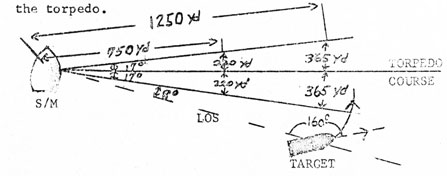
302.8 Anti-Escort Tactics (Suggested by COMSUBRON FIVE) This tactic has been tried in the attack teacher by the Submarine Development Group Fire, Control Party with results.
Purpose and Concept of operations:
Purpose: To determine the quickest method of successfully employing a MK 37 torpedo against a destroyer making hedge hog or depth charge attacks.
Concept: (1) Submarine already on defensive.
(a) At a depth below periscope depth.
(b) Employing evasive tactics, successfully enough to evade but not sufficient to break contact.
(2) Destroyer employing weapons that require him to pass close aboard to successfully attack.
(3) Submarine CO desires to regain the offensive as soon as possible.
(4) Good sonar conditions.
3-4
Operational Data:
This tactical idea is based on the destroyer turning for a reattack as soon as it is possible. If the destroyer does not, then she will not be reattacking in the minimum time, and will allow the submarine to take time to make deliberate torpedo attacks in the manner usually employed.
A destroyer making a quick reattack presents an angle on the bow to the submarine of about 160°, turns at a range of 750 to 1,250 yards and steams in for reattack. The MK 37 should hit as the destroyer is just completing the turn.
A hitting ablution deflection angle varies as follows for ranges 750 to 1,250 yards, AOB 90 to 150°.
Twelve knot target:
8 to 20°
Fifteen knot target:
13 1/2 to 30°
Eighteen knot target:
18 1/2 to 42°
The entire scale of deflection angles varies from a minimum of 8° to a maximum of 42°, a span of 34°. At a range of 750 yards, 34° subtends an arc with chord length of about 440 yards; 730 yards at 1,250 yards. A MK 37 torpedo traveling down the average deflection angle of 17 + 8 = 25° would come well within the 500 yards acquisition range of the torpedo.
EXAMPLE
Theoretically this firing solution is good with target ranges out to 1,500 yards.
It should therefore remain to set in the TDC the target information, obtained by visual observation and/or active and passive sonar information, set the final bearing, and shoot as seen as the deflection. angle of 25° has been set or shoot using the generated TDC solution. The recommended settings for the torpedo are as follows:
3-5
Running depth
80 feet
Speed
High
Enable
Minimum (600) yards
Search
Circle
Stratum
Above Limits
Homing
Passive
The ideal time to execute this shot is just as soon as the destroyer puts his rudder over to commence a reattack.
This idea has one final advantage. If the shot misses, another quick "down the throat" attack is possible before going deep on the defensive.
303 GENERAL EMPLOYMENT. This paragraph contains individual instructions peculiar to the employment of the MK 37-0 torpedo for the various members of the Fire Control Party with a general submarine fire control system. This doctrine, being based on the use of Deflection Angle Curves/Spread Plotter, requires individual command decision as to the members of the party best suited to use these curves and the plotter. The methods and mechanical usage of the curves are simple; the decisions to be made in selecting values of the various parameters require, however, a high degree of knowledge of tactical considerations.
303.1 Approach Officer. Monitor and confirm in decision making processes in the use of the Deflection Angle Curves or the Spread Plotter. Indicates the settings to be placed on the torpedo.
303.2 Fire Control Coordinator
a. Informs the approach officer when the best solution indicates the, target is within torpedo run.
b. Specifies limits of true bearing-rate to be used for dater-mining the fire control solution. These values must be as accurate as possible.
c. Keeps the approach officer advised of sonar reports regarding estimates of target depth, maneuvers, turn count and cavitation and continually evaluates the target solution.
303.3 Spread Plotter Operator
a. Receives target information from the fire control coordinator and should continuously be ready to provide a deflection angle for firing.
3-6
303.4 Deflection Angle Curve Operator. By using the Deflection Angle determined by the Spread Plotter and by selecting the correct speed curve can determine the zig coverage of each unit.
303.5 TDC or PK Operator.
a. Sets the tactical data arrived at by use of the Spread Plotter/DA Curves for an individual torpedo or for each torpedo in a spread.
b. Insures that sonar bearing is kept matched in the PK console.
c. Once target bearing has been matched, and the TDC/PK Operator has reported target AOB and speed set, normal firing procedure for the FC System involved can be followed.
303.6 Assistant TDC Operator or Angle Solver Operator.
a. Orders torpedoes warmed up (standby) at least 1 minute prior to shooting.
b. Informs the Approach Officer if the "Depth Differential Limitation will be exceeded. (See paragraph 302.5)
c. Orders required Enabling Run.
d. Conducts gyro check early in the approach and again. just be-fire firing.
e. Checks out all synchronous and preset functions early in the approach.
303.7 Firing Panel Operator or Control Unit Operator.
Insures torpedoes are placed in standby sufficiently in advance of shooting - at least 1 minute (15 seconds in an emergency).
304 VARIATIONS IN INDIVIDUAL FCS's
304.1 Employment with the MK 4 TDC with Presetter
304.1.1 General
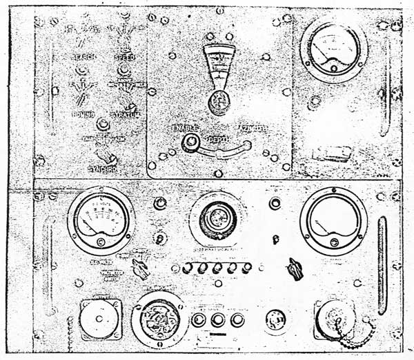
Submarines equipped with a MK 4 TDC and having a Presetter (See Figure 3-1) installed in the Torpedo Room can adequately fire the MK 37-0. The Presetter is used to set in synchronous and non-synchronous functions as ordered by telephone circuits from the conning tower.
3-7
Figure 3-1
3-8
The Presetter receives 400 cycle power from a 24V battery-powered alternator. It cannot be energized for long, continuous periods of time due to limited battery capacity. Recent tests indicate about 40 minutes continuous operation is the limit.
304.1.2 Design Limitations
Completion of OrdAlt 4095 on the MK 4 TDC provides for:
a. A Selective mechanical gearing ratio of 1.8:1 thereby increasing maximum solution time from 8 minutes to 14.4 minutes.
b. Allows for setting a minimum torpedo speed of down to 10 knots which in turn limits maximum torpedo speed to 35 knots.
The extended solution time permits sufficient time for generating a solution for the maximum run of the high speed torpedo. However, the TDC can not generate a solution for the low speed torpedo that has a torpedo run in excess of 7500 yards. See Article 212.6 to determine how deflection angles are set into
the torpedo using the TDC when the low speed torpedo run is in excess of 7500 yards.
304.1.3 Synchronous Settings.
a. Gyro Angle. Gyro angle will necessarily be transmitted by telephone and inserted into the Presetter manually. Using the Presetter, gyro angle can be set for any value. Insure careful setting of gyro angle to avoid exceeding the A.C.R. limit of 160 Right or. Left.
b. Enabling Run. Enabling run also can only be set in the Presetter in response to telephone direction. Using the Presetter, enabling can be set for any value; there are no limits except those of the torpedo itself.
c. Depth. Depth must be set at the Presetter in response to telephone direction. Depth can be set for any value; there are again no limits except the 1,000 feet maximum in the torpedo itself.
304.1.4 Non-Synchronous Settings.
All non-synchronous settings (speed, homing mode, horizontal
3-9
search and stratum) are set at the Presetter using four three-position switches. (See Figure 3-1) Indicator lamps above each switch are lighted when the selected function is set in to the torpedo. There are no warning lights to indicate lack of stratum protection.
304.1.5 Tactical Settings.
a. Speed. Speed for the MK 37-0 Torpedo will vary depending on the length of the enabling run since after enabling the sinuating course will reduce the torpedo speed of advance by about 5%. The latest figures available from Bureau of Weapons indicate torpedo speed will be:
High Speed
24.7 kts
+/- .57 kts
Low Speed
16.4 kts
+/- .22 kts
The following speed settings are recommended for firings with Enabling Run set at 600 yards:
High Speed
24.0 kts
Low Speed
15.8 kts
b. Reach, Turn Radius and Run Difference - set data as follows:
High Speed
Low Speed
(1) Reach (m)
= 13 yds
12 yds
(2) Turn Radius (Z)
= 30 yds+
25 yds*
(3) Run Difference (Uy)
= -44 yds
-40.3 yds
* NOTE: The lower limit of the "Z" external knob of the TDC is 75 yards. Since the turning radius of the MK 37 torpedo is less than 75 yards, the procedure specified on page 57 of OP1442A (First Revision) should be followed in setting Turn Radius.
304.2 EMPLOYMENT WITH THE FIRE CONTROL SYSTEM 106
304.2.1 Differences between Mods. Submarines equipped with the Fire Control System MK 106 may be divided into two main classes:
a. Ships equipped with Mods other than Mod 5.
b. Ships equipped with the Fire Control System MK 106 Mod 5 with the Control Panel MK 155 and the Control Unit MK 65.
3-10
The primary difference between the first and second classes is the manner in which depth and enabling run can be set. This difference will be noted under the discussion of settings; otherwise the two classes can be treated as one.
304.2.2 Design Limitations. Completion of OrdAlt 4095 on the MK 4 TDC provides for
a. A selective mechanical gearing ratio of 1.8:1 thereby increasing maximum solution time from 8 minutes to 14.4 minutes.
b. Allows for setting a minimum torpedo speed of down to 10 knots which in turn limits maximum torpedo speed to 35 knots.
The extended solution time permits sufficient time for generating a solution for the maximum run of the high speed torpedo. However the TDC can not generate a solution for the low speed torpedo that has a torpedo run in excess of 7500 yards. See Article 212.6 to determine how deflection angles are set into the torpedo using the TDC when the low speed torpedo run is in excess of
7500 yards.
304.2.3 Synchronous Settings.
a. Gyro Angle. Gyro angle will normally be transmitted automatically from the Angle Solver or inserted manually at the MK 65 Control Unit (MK 106 Mod 5) or the MK 15 or 22 Relay Transmitter which hive gyro angle limits of ± 150°. If an angle larger than 150° is transmitted, it will slew the torpedo gyro servo motor to 0°. To prevent this, engage the gyro setting hand knob on the Relay Transmitter before the Gyro Angle reaches 150°. On the MK 65 Control Unit the Gyro Angle Limit is adjustable to ± 165°
b. Enabling Run. In the MK 106 Mod 5 system, enabling run can only be set at the MK 65 Control Unit in the torpedo room in all other Mods of the MK 106 system it can either be set as enabling offset (± 5,000 yards maximum with OrdAlt 4094 completed) at the MK 32 Firing Panel (Conning Tower) or directly as enabling run at the MK 15 or 22 Relay Transmitter (Torpedo Room). When using the Deflection Angle Curves, it is usually more desirable to set enabling run directly. In this case, enabling run must be transmitted by phone to the torpedo room.
c. Depth. In the MK 105 Mod 5 system, depth can only be set at the Mk 65 Control Unit in the Torpedo Room. In all
3-11
other Mods of the MK 106 system, it can either be set at the MK 32 Firing Panel (Conning Tower) or at the MK 15 or 22 Relay transmitter (Torpedo Room). The Depth Limit can settings on the MK 65 Control Unit/MK 15 or 22 Relay Transmitters should be checked to insure that the settings correspond with the running limitations of a MK 37 Torpedo (4-1,000 feet).
Non-Synchronous Settings. All non-synchronous settings (speed, homing mode, horizontal search and stratum) for the MK37 Torpedo can be made at the MK 65 Control Unit (Fire Control System MK 106 Mod 5) or the MK 32 Firing Panel (Fire Control System MK 106 all other Mods). It should be noted that the Torpedo Functions Memory Plate does not have a red dot to indicate that the Stratum setting is applicable to this torpedo. This is easily remedied by filling in the appropriate white circle with red paint. Also, the stratum: warning light on the MK 32 Firing Panel is mislabeled. It should read "No Limit" vice "Above or No Limit". This light warns the firing ship that it is not protected by the stratum feature.
Tactical Settings.
a. Speed. Speed will vary depending on the length of the enabling run since after enabling the sinuating course will reduce the torpedo speed of advance by about 5%. The latest figures available from Bureau of Weapons indicates that torpedo speeds will be:
HIGH Speed:
24.7 knots * .57 knot
LOW Speed:
16.4 knots * .22 knot
The following speed settings are recommended for firing with Enabling run set at 600 yards:
HIGH Speed:
24.0 knots
LOW Speed:
15.8 knots
b. Reach. Turn Radius, and Run Differences - Set data as follows:
HIGH SPEED
LOW SPEED
(1) Reach
= 13 yards
12 yards
(2) Turn radius (Z)
= 30 yards
25 yards*
(3) Run Difference (Uy)
= -44 yards
-40.3 yards
* NOTE: The lower limit of the "Z" external knob of the TDC is 75 yards. Since the turning radius of the MX 37 torpedo is less than 75 yards, the procedure specified on page 57 of OP 1442A (First Revision) should be followed in setting Turn Radius.
3-12
304.3 Employment with the Fire Control System MK 101.
304,3.1 Design Limitations. The MK 101 Fire Control System will solve the fire control problem for the MK 37 torpedo in the majority of solutions likely to be encountered. 'There is, however, a minor limitation imposed by the fact that the MK 11 Angle Solver, MK 101, Mod 3, 9 and 10 will not generate a solution for a torpedo run time greater than 15 minutes. This is a limitation encountered when firing the torpedo in LOW speed with a run in excess of 8,500 yards. The MK 18 Angle Solver MK 101 Mod 13, provides for computation of torpedo run solution out to 35,000 yards and requires no such special procedure.
304.3.2 Synchronous Settings.
a. Gyro Angle. Gyro angles will normally be transmitted automatically from the angle solver or it can be set manually at the MK 15 or MK 22 relay Transmitter in the torpedo room. The MK 15 or 22 Relay Transmitter has a gyro-setting hand knob on the MK 15 Relay Transmitter which should be engaged before the gyro angle reaches 150°.
b. Depth. Torpedo running depth can be set either at the Angle Solver MK 11 or at the MK 15 or 22 Relay transmitter. The depth limit circuit for torpedoes in the MK 101 Fire Control System is set at a 10 feet/second climb or dive rate. The MK 37 climbs at 19.3 feet/second and dives at 30 feet/ second before enabling. Thus, the depth limit warning light on the Firing Panel does not necessarily indicate that the depth limit is being exceeded. It will, however, serve as a remainder to check the solution when the depth differential between the firing submarine and the target is large and the range is short.
304.3.3 Non-Synchronous Settings. All non-synchronous settings (speed, homing mode, horizontal search and stratum) for the MK 37 torpedo can be made at the MK 21 Firing Panel. It should be noted that the Torpedo Functions Memory Plate does not have a red dot to indicate that the stratum setting is applicable to this torpedo. This is easily remedied by filling in the appropriate white circle with red paint. Also, the stratum warning light on the MK 21 Firing Panel is mislabeled. It should read "No Limit" vice "Above or No Limit". This light warns the firing ship that it is not protected by the stratum feature.
304.3.4. Tactical Settings.
3-13
a. Ballistic Cams and Plugs. Ballistic cams and plugs are now available for the MK 37-0 torpedo. The plugs will provide speed values of 24.7 knots in high speed and 16.4 knots in low speed. To provide torpedo speed appropriate for the Snake Mode, the following action is required:
(1) For the MK 11 Angle Solver (MK 101 Mods 3, 9 and 10). Use the Speed Correction Control, which has a maximum Correction of ± 9%, to set the proper speed. Example -To set speed of 24 knots, set correction scale to read -2.8%.
(2) For the MK 18 Angle Solver (MK 101 Mod 13). Use the Ballistic Plug Control (jSz) which provides for offsetting the nominal running speed with a correction range of ± 3 knots. Example - To set exercise speed of 24 knots, which is recommended for the Enabling Run of 600 yards, set Ballistic Plug Control correction to read -.7 knots.
4.4 Employment with the FCS MK 112.
4.4.1 Design Limitations. The MK112 FCS will solve the fire control problem out to a maximum torpedo run of 35,000 yards which is more than adequate for the MK 37-0 torpedo.
4.4.2 Synchronous Settings.
a. Gyro angle is normally solved for in the Weapons Order Generator section and is automatically transmitted to the torpedo. Gyro angle may also be inserted manually at the Weapons Order Generator or at the Torpedo Control Unit in the Torpedo Room.
b. Torpedo running depth is normally inserted manually with a hand crank at the Weapons Order Generator. An alternate method is provided through a hand crank on the Torpedo Control Unit.
c. Enabling Run Offset (within the limits ± 3,000 yards) may be set by handcrank at the Weapons Order Generator to modify the computed torpedo run. This modified torpedo run is then transmitted, through the Torpedo Control Unit, to the torpedo as Enabling Run. At the Torpedo Control Unit Enabling Run is set by hand crank, which then overrides the W.O.G. signal, from 0 to 35,000 yards. For firing MK 37-0 torpedoes, enabling will normally be set at the Torpedo Control Unit.
3-14
304.4.3 Non-synchronous Functions. All non-synchronous functions are normally inserted at the Weapons Order Generator. If necessary, however, these functions may be inserted at the Torpedo Control. Unit in the torpedo room.
304.4.4 Tactical Settings.
a. Ballistic Cams and Plugs. Ballistic cams and plugs for the MK 37-0 torpedo are available. The plugs will provide speed values of 24.7 knots in HIGH speed and 16.4 knots in LOW speed. To provide torpedo speed, appropriate for the Snake Mode, the following action is required:
(1) Use the Ballistic Plug Control (jSz) which provides for offsetting the nominal running speed with a corrective range of ± 3 knots. Example - to set exercise speed of 24 knots, which is recommended for an Enabling Run of 600 yards, set Ballistic Plug Control correction to read -.7 knots.
304.5 Employment with the Fire Control System MK 113.
304.5.1 Design Limitations. The MK113 FCS is presently capable of handling problems within the following limits:
Range
300 - 200,000 yards
Speeds
0 - 50 knots
Range Rate
+/- 100 knots
Bearing Rate
+/- 1.0°/minutes
Torpedo Enabling Run
0 - 20,000 yards
The Torpedo Enabling Run Counter in the Angle Solver Section of the MK 75 Attack Director is also the only indication of torpedo run. If the Enabling Run Hand Crank is engaged and 600 yards Enabling Run set: into the torpedo, then there is no indication of computed Torpedo Run. This procedural limitation will necessitate setting the Enabling Run immediately before firing.
304.5.2 Synchronous Settings.
a. Gyro Angle - Gyro Angle is normally solved for in the Angle Solver Section of the Attack Director and is automatically transmitted to the torpedo. Gyro angle may also be inserted manually at the Angle Solver Section for transmission to the torpedo.
b. Torpedo Running Depth. Running depth is inserted manually with a handcrank at the Angle Solver Section.
3-15
c. Enabling Run. As previously indicated, the Torpedo Enabling Run Counter is also the indication of computed torpedo run. Enabling Run may be set in one of the following two ways:
(1) Enabling Run Offset (+/-3,000 yards) may be inserted by handcrank at the Angle Solver Section to modify the computed torpedo run, resulting in the value of Enabling Run to be transmitted automatically. The Offset is indicated on a counter immediately adjacent to the Enabling Run Counter.
(2) Enabling Run may be inserted manually by clutching in the Torpedo Enabling Run Counter Handcrank and overriding the computed value for automatic transmission to the torpedo. This will normally be done immediately before firing.
304.5.3 Non-Synchronous Settings. All non-synchronous functions are inserted at the Plotter Section of the Attack Control Console.
304.5.4 Tactical Settings.
a. Ballistic Cams and Plugs.
Ballistic cams and plugs are available for the MK 37-0 torpedo for use in the MK 113 FCS. The plugs will provide speed values of 24.7 knots in HIGH speed and 16.4 knots in LOW speed. To provide torpedo speed appropriate for the Snake Mode, the following action is required:
Use the torpedo correction speed on the ballistic plug which provides for offsetting the nominal running with a corrective range of ± 10% - Example - To set exercise speed of 24 knots, which is recommended for an Enabling Run of 600 yards, set correction to read - 2.8%.
305 LATITUDE CORRECTION FOR THE MK 37-0 TORPEDO
305.1 The torpedo MK 37 Mod 0 gyro is balanced and adjusted for operation at a latitude of 0°. The Fire Control System MK 106, when not equipped with Angle Solver MK 18, provides no means for setting a latitude correction when shooting the torpedo MK 37 Mod 0. The same condition exists in the Fire Control System MK 101 when shooting the torpedo MK 37 Mod 0 at a latitude above 70°.
3-16
If gyro creep is not corrected, the torpedo would be displaced approximately 1,450 yards from the intended torpedo track when tired in LOW speed, maximum torpedo run, and at a latitude of 70°.
305.2 For submarines with Fire Control System MK 106 not equipped with Angle Solver MK 18, the correct latitude correction can be determined by proper use of the charts in Figures 3-2 and 3-3. The corrections obtained from the charts can be directly converted to gyro angle corrections and applied to the TDC via the Angular Offset Knob (spread knob).
305.3 For submarines with Fire Control System MK 106 equipped with
Angle Solver MK 18, Fire Control System MK 101 and Fire Control System MK 112, latitude gyro creep for any torpedo is corrected by the latitude correction controls on the fire control equipment in latitudes of 0° to 70°. There are no provisions for setting a latitude gyro creep correction for latitudes above 70° at the present time.
305.4 In all other underwater Fire Control Systems (MK 113 Mod 2 and 113 Mod 5), provisions are made for correcting the latitude gyro creep for any type torpedo for latitudes from 0° to 90°.
4-1
SECTION 4 TACTICAL EMPLOYMENT
401 GENERAL
401.1 No clearly defined 'rules' for the tactical employment of the MK 37-0 Torpedo are discernible at this time. This section will survey the factors which are considered to most significantly affect the decisions made to optimize the firing situation. We will do this in two parts by discussion of:
a. Favorable Firing situations
b. Maneuvers to create favorable firing situations
401.2 For purposes of clarity it must be restated that Sections 1 and 2 set forth the recommended choices of torpedo settings (including gyro angle) which apply to various situations which may exist. We are concerned, in this section, with the choices we can make which result in the then 'existing' situation.
402 FAVORABLE FIRING SITUATIONS
402.1 General. In general, a favorable firing situation can be said to exist it the number of torpedoes to be fired, which will provide the required assurance of hitting the target, is minimized. Alternatively, if the number of torpedoes is not a consideration, it is one in which each torpedo (or set of torpedoes) when aimed with the optimum settings has the greatest probability of hitting the target. The factors which constitute such a favorable situation are discussed below. Only those which are to some degree under the control of own ship are considered.
402.2 Target Range. A closer range is clearly more favorable than a longer range, other conditions being the same and provided the ability of the target to detect the firing submarine or the torpedo is not enhanced. In very approximate terms the situation worsens as the ratio of target range-to-torpedo acquisition range increases.
402.3 Target Aspect. A study of the material in Appendix F (MK 37-0 Tactical Doctrine Part II) "acquisition-to-hit conversion", reveals that the aspect of the target (seen by the torpedo on acquisition) should lie between the following approximate limits:
4-2
Active Torpedo - AOB 0° to 30°; 095° to 180°
Passive Torpedo - AOB 090° to 180°
(Target speed and torpedo speed modify these limits to a great degree)
This limitation is placed on the torpedo for a hit on the first pass.
402.31 It follows, therefore, that there will be favorable (and unfavorable) target aspects (as seen by the firing submarine); these will depend on the speed of the target and whether a high speed or low speed torpedo is fired and, of course, whether active or passive. Figures F-2 through F-5 display acceptable/unacceptable target aspect sectors for the conditions indicated. These figures do not take into consideration the acoustic beam of the torpedo. This omission will have only a minor effect.
402.32 The design feature which allows the MK 37-0 torpedo to have reattack capability does not cause the aspect limitation to be of paramount importance. An excerpt from the Naval Torpedo Station, Keyport - Naval Underwater Ordnance Station, Newport Joint Report 378 concerning firings conducted at DABOB BAY to evaluate aspect limitations is listed below:
"Torpedo hit capability is strongly dependent on reattack capability. In the active mode 73% of torpedoes which acquired the target scored a hit, but only 19% hit during first attack. If runs which failed because of surface effects were excluded, a 90% hit capability would be indicated. In the passive mode, the majority of torpedoes were fired from within Turn Rate Limited zones and were not allowed to reattack. For this reason similar estimates for the passive torpedo would be of low reliability. Results indicate, however, that passive hit capability would exceed 75%. (These figures do not include possible degradation due to component defects and fire control errors).
402.4 Torpedo Run. Relative positions from which the torpedo can be fired and yet not exceed maximum torpedo run have also been displayed in Figures F-2 to F-5. For longer torpedo runs, errors in torpedo position due to: gyro setting error, gyro precession error and a torpedo speed differing from that assumed, will tend to reduce the assurance of target acquisition. A consideration of normally encountered errors has lead to the view that, provided a 'margin' of
4-3
about one-half degree is left in the choice of deflection angles, longer torpedo runs per se do not create a more unfavorable firing situation.
402.5 Target Condition. From almost all considerations a cavitating target constitutes a 'favorable' target. The MK 37-0 torpedo can be set in the passive mode which is optimum because the Passive mode torpedo is not susceptible to ice or surface capture and the firing interval between units of a passive salvo is less than the interval between units of an active salvo. If the target is on the threshold of cavitation then consideration should be given to firing a low speed passive torpedo at: the target because of the increased acquisition range caused by the increased acoustic sensitivity. Ii the target is not a threshold cavitating target then consideration should be given to tiring all units in HI speed unless the torpedo run is greater than 10,000 yards. This will allow less time for the target to maneuver and thus invalidate the effectiveness of the weapon.
402.51 Recognizing the possibility but, in most cases, the unpredictability of variations in the target condition and motion it can readily be seen that the decision whether or not to accept the existing situation or to wait for an improved situation will be one requiring considerable knowledge of the weapon system and careful judgment.
403 MANEUVERS TO CREATE FAVORABLE FIRING SITUATIONS
403.1 The approach officer has, of course, control of own speed, course, and depth and, to some degree, the target range and aspect. He can, also, to a larger degree, control the time of firing. He must make the best available choices so as to improve, as possible, the firing situation.
403.2 As indicated in Section 2,the derivation of deflection angles required the setting of limits on the various target parameters: true bearing rate and range when using the Spread Plotter and additionally speed and aspect when using the deflection angle curves. The actual values must lie between limits set (to be assured of acquisition) and the narrower the limits set the fewer the torpedoes that must be tired to assure coverage. It is important, therefore, to capitalize on all available technical information which may permit accurate definition of these limits.
4-4
403.21 Target Speed. Maximum use must be made of any/all available intelligence of enemy capabilities. A good estimate of speed will assist in the Nav/Strip Plot analysis for target course and range.
403.22 Target True Bearing Rate. This can be obtained by:
a. Heading directly for the target preferably, or
b. Converting relative bearing rate by separating-out own ship contribution (this requires a knowledge of target range)
403.23 Target Range. In the passive, bearing tracking situation maximum utilization must be made of:
a. Ekelund ranging.
b. Nav/Strip Plot analysis.
403.24 Target Aspect (AOB). Intelligence as to the base track of the enemy may be of some assistance. Use of the deflection angle curves will indicate the amount of zig coverage afforded by each unit. If the base track of the target can be predicted then the number of units required for a hit can be minimized.
403.25 Target Depth. No techniques are readily available to submarines fitted with standard equipment to solve for depth. Equipments/techniques under development may solve this problem. Maximum. utilization must be made of intelligence available as to enemy depth capabilities. Since we are at times unable to predict the target depth, a depth spread. of units is necessary. In this situation, torpedo running depth settings should be as stated in Section I. When torpedoes are spread in depth, they are susceptible to interference if the minimum firing interval listed below is not followed:
a. Between units of an active salvo: 2 minutes and 15 seconds.
b. Between units of a passive salvo: 15 seconds
404. SALVO FIRING
404.1 Salvo firing within the Force plus reports from NTS
Keyport on their firings indicate that the torpedo MK 37-0 is susceptible to mutual interference when fired in a salvo.
4-5
404.2 Following information concerning salvo firing of torpedoes MK 37-0 is forwarded for guidance:
404.2.1 For salvo firing, active mode, high speed, use a minimum two minutes and 15 seconds firing interval to assure torpedoes are at least 1,800 yards apart at enabling. Compute a new deflection angle for each successive unit in salvo IAW MK 37-0 Tactical Doctrine as required by a change in the Fire Control solution which may develop during two minutes and 15 seconds interval.
404.2.1.1 If salvo was required initially to provide complete range coverage, ensure that recomputed deflection angle covers targets at ranges not covered by deflection angles previously used in the salvo.
404.2.1.2 If the salvo was required initially to provide target depth coverage, the same minimum firing interval is necessary since the torpedo is susceptible to mutual interference whether the units are spread in depth or in azimuth.
404.2.2 For salvo firing, passive mode, use minimum 15 seconds firing interval whether the salvo is spread in azimuth or in depth.
404.2.3 Other fire control settings IAW MK 37-0 Tactical Doctrine.
404.2.4 In addition, it should be noted that active mutual interference can exist at ranges up to 2,400 yards. Such may occur when units are pointed at each other when the first unit is circling for reattack. To preclude passive interference under outstanding sonar conditions, a minimum firing interval of 30 seconds should be used.
405 SURFACE CAPTURE
405.1 Surface capture is the homing of a MK 37-0 torpedo on
echoes from the surface. This happens in rough or choppy seas when the torpedo is set in the ACTIVE mode.
405.2 The fact that torpedoes fired in the active mode were susceptible to surface capture hag been noted from fleet firings. The specific parameters that caused surface capture were not known so a series of firings were established to pinpoint these parameters. These firings were conducted during SPRINGBOARD 1963. The firings were
4-6
conducted in two phases. Phase I was a test for surface capture without the use of a target and Phase II a test for surface capture utilizing a target. A total of twenty-tour valid firings were conducted in Phase I and seven valid firings in Phase II. The firings were conducted in sea states one, two and three; sea state being defined in H.0, Pub #9, page 1059.
405.3 Listed below is a summary report on the problem area of surface capture:
a. To. date, fleet firings have indicated no surface capture problems with the Passive Mode MK 37-0 torpedo. As a result of this the SPRINGBOARD firings were established to determine the effect of sea state on the Active Mode torpedo. However, on two of the firings the unit was fired in Passive Mode instead of Active Mode in a sea state three. Neither of these units was surface captured. These Firings tend to confirm the tact that the Passive Mode torpedo is not susceptible to surface capture.
b. The Active Mode torpedo when tired in sea state one is not susceptible to surface capture. This is confirmed by fleet firings and a small number of firings at SPRINGBOARD.
c, Thirteen valid. Active Mode firings were conducted during Phase I in sea state two. The running depth for these units varied between 80 and 150 feet. Four torpedoes or approximately 31% of the units were surface captured.
d. Eleven valid Active Mode firings were conducted during Phase I in sea state three. The running depth For these units varied between 80 and 150 feet. Seven torpedoes or approximately 64% were surface captured.
e. In Phase II, two valid firings were conducted in sea state one Neither unit acquired the target nor was surface captured. One valid tiring was conducted in sea state two, this unit was not surface captured but did acquire and attack the target. Four valid firings were conducted in sea state three. One unit was not surface captured and made a normal attack. The other three units were surface captured. Two of these surface captured in the vicinity of the target and the possibility exists that some of the returned echoes were from the target. However, it is believed that: had these torpedoes been "to hit" shots, they would not have hit the target. All units were fired in Active Mode.
4-7
405.4 Naval Underwater Ordnance Station, Newport is currently working on design changes to the circuitry of the MK 37-0 torpedo to prevent surface capture but until such time as changes are made personnel should be aware that the MK 37-0 torpedo when tired in the Active Mode in sea state two or greater is susceptible to surface capture.