Sofar (Sound Fixing and Ranging) is a long-range position-fixing system that uses explosive
sounds in the permanent sound channel of the
ocean. A fix is determined from the differences
in arrival times, at known geographic positions,
of a signal that is sent from any given point. The
useful range from the signal source to the monitor
stations can exceed 3,000 miles.
Sound Channel
A sound channel is formed by a layer of water
that has a negative velocity gradient overlying an
adjacent layer that has a positive velocity gradient. Under these conditions any sound signal that
originates at a depth above and below which there
is a higher velocity, is refracted back and forth so
as to become horizontally channeled. Sound rays
originating with an initial upward inclination are
refracted downward, and those originating with
an initial downward inclination are refracted upward. A central bundle of rays is channeled so
that the rays never reach either the surface or the
bottom. These rays, plus the low frequency of
the sound source, are responsible for the long
ranges obtained.
As a result of channeling, the signal intensity is
not subject to attenuation resulting from (1) normal spreading because the spread is confined primarily in the horizontal plane, or (2) surface and
bottom scattering, because the sound is always
confined at middepths. If explosive charges,
which produce low frequencies (30 to 150 cycles
per second), are used, losses caused by absorption
and volume scattering are kept at a minimum-about 0.002 db per 1,000 yards in the permanent
sound channel of the ocean.
The vertical velocity distribution that produces
the sound channel is caused by changes in
temperature with depth. Above the axis of the sound
channel there is a pronounced negative thermal
gradient with a corresponding marked negative
velocity gradient. This negative thermal gradient is due to the thermocline-the water layer in
which most of the change in temperature between
the surface and the bottom takes place. Below
the axis of the sound channel the thermal gradient
is only slightly negative or is negligible. The
positive velocity gradient that results from the
pressure effect of the water column exceeds the
negative velocity gradient that is due to the slight
decrease in temperature. Consequently, the
velocity increases.
The depths at which the signal originates and is
received govern the strength of signal and hence
the range of operations. The optimum depth for
maximum signal intensity is that of minimum
velocity (axis of the sound channel). The velocity
of sound in the sound channel affects the distance
determinations and hence the accuracy of the
method.
Factors Affecting the Use of Sofar
In addition to the velocity of sound and the
depth of the signal, the following other factors
affect the use of sofar:
1. Number of stations receiving the signal;
2. Accuracy of the geographic coordinates of
base stations;
3. Geodetic data used at base stations;
4. Local departures of the earth's shape from
that assumed;
5. Depth at which the receiving hydrophone
is placed;
6. Depth at which the signal is fired;
7. Mean velocity of transmission;
8. Number of sound rays in the sound channel;
9. Shadows cast by obstacles (sea mounts,
islands, and coast lines);
281
10. Arc of reception at the hydrophone site;
11. Local topography at the hydrophone site;
12. Length of cable from the hydrophone to a
shore station;
13. Background noise level at the hydrophone
site;
14. Reverberation from the bottom adjacent
to the hydrophone site;
15. Intensity of the signal.
Position Determination
The accuracy of any position determination
using sofar depends to a great extent on a knowledge of the velocity of transmission. Of equal
importance is the number of sofar stations receiving a signal. When three or more stations receive
a signal, the location where it originated can be
determined fairly accurately (within less than 10
miles). As the number of stations receiving a
signal increases, the accuracy of the fix increases.
For ease in illustrating the principles involved
in making a sofar fix, a plane surface will be
assumed. In actual systems, compensations are
made for the curvature and the ellipticity of the
earth.
Example-Three stations on the same shore-A, B, and C-receive a signal. Determine the
position of shot P when the arrival times are
11:00:00 at A, 11:02:30 at B, and 11:05:00 at C.
In figure 16-1 the arrival at B was B - A (2 min
30 sec) later than at A, and the arrival at C was
C - A (5 min 00 sec) later than at A. With
the velocity known, circle B can be constructed
with radius b equaling the velocity times the time
lag at B. Similarly, circle C can be constructed
with radius c equaling the velocity times the time
lag at C. Then the center of the circle that is
tangent to circles B and C and passes through A
must define the location P from which the signal
originated. Point P is at a distance x from A, x+b
from B, and x+c from C.
If the problem involved stations on opposite
coasts, it could be solved in the same manner.
In actual practice one of the stations would act
as central plot. The other stations would send
their arrival times by radio to central plot. There,
by use of special charts, the position would be
determined within a few minutes after all arrival
times were received. Because of the relatively
slow travel time of sound in water (less than
5,000 ft/sec), it may be as much as 1 hour between
the time the signal is thrown overboard and a fix
is obtained at central plot. (In sofar terminology
the signal is the sofar bomb.)
Determining the Range From the Signal Duration
The distance that a signal has traveled can be
estimated from the duration of the signal. The
greater the range of transmission, the longer is
the signal. This phenomenon is related to the
ray paths followed in the sound channel. The
first sound to arrive is weak and comes over the
longest path, but it arrives first because of the
higher velocities encountered along this path.
The last sound to arrive comes over the shortest
path-along the axis of the sound channel and
the path of minimum velocity. Thus, the longer
the distance, the greater the time differential
between the first and last arrivals. Signal duration can be affected also by changes in the vertical
velocity distribution and the depth at which the
signal originates.
Because the time interval between successive
arrivals decreases as the path along the axis is
approached, and because the number of axial
crossings and overlappings of arrivals increases
as the path along the axis is approached, the
intensity of a signal increases with duration of
Figure 16-1. -Making a sofar fix.
282
signal until the last sound arrives over the axial
path. The end of the signal is abrupt. The
effect is similar to the interruption of a kettledrum
crescendo, the sound becoming louder and louder
and terminating abruptly. This effect makes
those signals that originate at or near the axis
of the sound channel easy to recognize either
aurally or visually.
At shore stations where the hydrophone is on
the bottom at a depth equal to that of the axis of
the sound channel, the signal is followed by reverberation, which results from the backward scattering
of sound off the bottom slope behind the hydrophone. Although the intensity of this reverberation is relatively high, it is not likely to mask the
distinguishing pattern of the sound-channel arrival.
A visual representation of a typical signal arrival
as recorded by a power-level recorder is shown in
figure 16-2. This figure shows that the signal
Figure 16-2. -Typical sofar signal.
duration, X, is a function of both range and noise
level. Because the noise level is variable the
signal duration can be used to give only an approximation of the minimum range.
Determining the Mean Velocity of Transmission
All fixes in sofar depend on resolving into distances, the differences in arrival times of a signal
at different monitoring stations. This computation can be made only if the velocity of sound
transmission is known. The velocity can be determined either by (1) computing the sound transmission velocity at the axis of the sound channel
from temperature, salinity, and depth observations
or (2) making empirical determinations from shot
travel-time data taken over known distances.
Because of the scarcity of travel-time observations,
velocity determinations are customarily established on the basis of the hydrographic data.
The velocity of sound transmission for a given
temperature, depth, and salinity can be determined
from graphs, tables, circular refraction
slide rules, or hydrographic slide rules. If the
circular slide rule or the British Admiralty Tables
are used, the velocity is based on a salinity of 35 0/00
(35 parts per 1,000). If the observed salinity is
greater than this value, the velocity must be
increased at the rate of 4.3 feet per second per part
salinity. If the salinity is lower, the correction
must be subtracted. The effect of depth is to
raise the velocity 1.82 feet per second per 100 feet
of depth.
Because of changes in the depth of the axis of
the sound channel with latitude, and because of
other changes in the velocity structure with latitude, it may be necessary to have a series of zones
with different mean velocities for varying distances
from each station. Such a system is more applicable when monitoring in a north-south direction
than in an east-west direction. For example,
from Hawaii to California tile axis of the permanent sound channel varies not more than about
400 feet in depth and the velocity is constant
within 8 feet per second. From the Aleutians to
Hawaii the axis depth changes about 2,000 feet
and the velocity about 36 feet per second.
How well can mean velocities based on hydrographic data serve for operations? This question
cannot be answered satisfactorily until a pattern
of shots fired at known positions is triangulated at
a network of shore-based stations. Geodetic
errors of position for the monitoring stations may
be so great that empirically derived apparent
velocities have to be used to obtain an accurate fix.
Effect of Depth at Which Signal Is Fired
The depth at which the signal should be fired is
the depth of the axis of the permanent sound
channel. This depth changes with oceans and
with latitude. The axis of the permanent sound
channel in temperate latitudes is about 350 fathoms
in the Pacific Ocean and about 680 fathoms in the
Atlantic Ocean. However, in Arctic and Antarctic
areas the axis may be at depths of less than 100
fathoms.
In general, the firing off the axis of the sound
channel distorts the signal. The distortion results
from changes in both the geometry of the ray paths
and the velocity of transmission. Shooting well
off the axis of the channel changes the travel-time
relation between the axial ray and the bounding
ray of the sound channel. The bounding ray is
283
that ray which just grazes the surface or bottom
without being reflected. As a result of the changes
in paths, the sound along the path of the bounding
ray may or may not arrive first. At very shallow
depths the sound along the axial path may arrive
first; if so, the peak intensity comes at the
Figure 16-3. -Signal (underwater sound) Mk 22.
beginning of the signal rather than at the end. Records
of signals from depth charges that were fired near
50 fathoms when the sound-channel axis was at 700
fathoms, show the peak intensity at the beginning
of the signal. Upon the arrival of the signal,
there is an abrupt rise from noise level to a high
intensity, after which there is a gradual decay to
noise level. This picture is the exact reverse of
that obtained for a signal originating at the depth
of the axis of the sound channel. As ray paths are
reversible, a signal with a peak near the beginning
also can be expected if the shot is fired at the
depth of the axis of the sound channel but is
received near the surface.
SOFAR BOMBS
Requirements
The problem of creating a bomb and detonator
for use with sofar is particularly difficult because of
the wide range in firing depths required. In addition, there are other problems, such as weight, cost,
sinking time, and reliability of detonation.
The general requirements are as follows:
1. A sofar bomb must fire at the pressure at the
axis of the sound channel, which varies from
500 to 2,000 pounds per square inch.
2. The detonator must fire either by pressure
or, preferably, by a reversal of velocity gradient when at the depth of the axis of the sound
channel.
3. The bomb must contain a sufficient explosive
charge to be heard over the area of operations;
must have a sinking time of not more than 5
minutes; and must be reliable, light, compact,
and relatively inexpensive.
4. The bomb and detonator must be safe against
accidental detonation.
Various types of bombs have been developed and
tested for use with sofar. The only one to reach
full production is the Mk 22.
MK 22 MODS 0 AND 1 SOFAR SIGNALS
General
Signals (underwater sound) Mk 22 Mods 0 and 1
were developed as explosive sound sources for use
with the sofar system. The two modifications of
the signal are fundamentally the same; each contains 4 pounds of TNT and a pre-settable hydrostatic fuse for exploding the TNT at any one of six
depths between 1,500 and 4,000 feet. Specially
284
prepared charts, which show the sound channel
depth in various areas of the oceans, are supplied
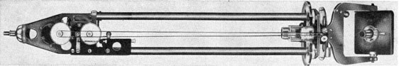
with the signal. The Mod 0 signal, shown in
figure 16-3, has a tail vane and is intended primarily to be dropped from an aircraft in distress.
The Mod 1, not illustrated, has no tail vane, and
is for dropping over the side from a disabled ship
or life boat.
Description
Each signal consists of the body part or signal
tube, containing 4 pounds of TNT, and fuze Mk
175 Mod 0, which is screwed onto the nose end of
the tube. Addition of the tail vane to the other
end of the body identifies the Mod 0 signal.
Before the signal is launched or dropped over-board, the cotter pin that locks the arming plunger
must be removed. As long as the arming plunger
protrudes through the diaphragm retainer the fuze
is unarmed and safe. If the signal is to explode at
a depth of 1,500, 2,000, 2,500, 3,000, or 3,500 feet,
the bottle cap that covers the appropriate depth-setting port is taken off by means of the attached
bottle opener. Removing the bottle cap exposes
a rupture disk that closes the inner end of the port.
Depth settings are indicated on the nose plate.
If the signal is to detonate at 4,000 feet, no cap is
removed, because at this depth, sea water operates
the fuze through an open port directly below the
nose plate. When the signal reaches the desired
depth, the exposed disk is ruptured and sea water
fills the fuze-head cavity, and exerts pressure on
the firing diaphragm. The firing diaphragm is
snapped forward and causes the shear wire, which
Figure 16-4. -Fuze used with sofar bomb.
239276°-53-19
285
Figure 16-5.-Map of northeast Pacific sofar network.
holds the stab-type firing pin in place to give way.
The firing pin then strikes the detonator.
The detonator remains in the safe position, even
after removal of the safety cotter pin until, at a
depth of between 750 and 1,200 feet, the pressure
of sea water acting on the arming plunger and on
the stiff copper arming diaphragm, moves the
detonator permanently into the armed position.
(See figure 16-4.) The arming plunger seats so
that the detonator is aligned between the firing
pin and the lead-in to the booster. The explosive
train follows the following path: detonator, lead-in, booster, and main charge.
Another type of bomb that has been developed
for use in signaling by means of sofar, is the
UNUSL multiple-shot bomb. This bomb is composed of four explosive sections, which fire at predetermined intervals, with a 90-second period after
the detonation of the first section. The timing of
the shots is controlled by a fifth section of the
bomb. By means of this device coded messages
may be sent from the ships to the sofar monitoring
stations.
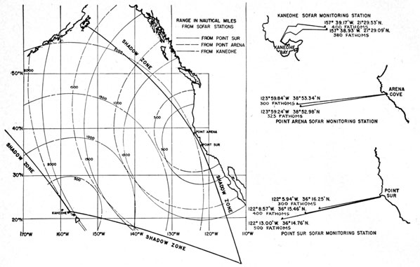
THE SOFAR NETWORK
The northeast Pacific sofar network (figure
16-5) consists of three monitoring stations located
at (1) the U. S. Coast Guard Light Station, Point
Sur, Calif., (2) the U. S. Coast Guard Lifeboat
Station, Point Arena, Calif., and (3) the Naval
Air Station, Kaneohe Bay, Oahu, T. H. Each
station consists, essentially, of hydrophones
planted offshore on the ocean bottom and connected by underwater cable to amplifying and
recording equipment on the beach.
All three sofar monitoring stations are equipped
with two channels, each consisting of (1) a beach
amplifier located in a beach hut, (2) land lines connecting the beach amplifier and main monitoring
equipment, and (3) the main monitoring equipment.
286
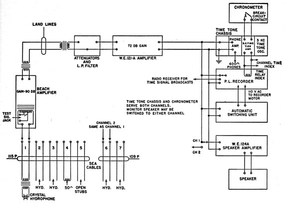
Figure 16-6. -Block diagram of one channel of a sofar monitoring station.
The main monitoring equipment is composed,
essentially, of the following units:
1. Western Electric Co. 121A amplifier for each
channel;
2. Power-level recorder for each channel;
3. Automatic switching unit;
4. Monitor-speaker amplifier and speaker, which
may be switched to either channel;
5. Chronometer and related time-tick circuits
for both channels;
6. Signal generator and calibration set for putting known calibration signals into the
beach amplifier.
A simplified block diagram of one channel of a
sofar monitoring station is shown in figure 16-6.
At the left are the sea cables terminating at the
lower panel of the beach-amplifier rack. The
hydrophone numbers correspond to the numbers
appearing next to each jack on this panel. No
other numbers are used to designate hydrophones.
APPLICATIONS
The most publicized application of sofar has
been for position location in air-sea rescue work.
The outstanding advantage that sofar has over
other air-sea rescue systems of signaling is that it
operates automatically. The only action required of the operator is removal of the cotter pin.
Then, regardless of whether the signal bomb is
thrown overboard or sinks with the wrecked craft,
the bomb fires and sends the signal because it is
armed and detonated by pressure.
Another application of sofar is for long-range
submarine signaling. By means of the multiple-shot bomb, signals can be sent at any fixed time
interval. In this way coded messages can be sent
great distances from any craft at sea. Special
equipment is not needed, and with a network of
monitoring stations messages are sure to be
received.
287
Harbor Defense
HARBOR UNDERWATER DETECTION
Harbor underwater detection, a little-publicized
field of naval defensive warfare, is a part of the
answer to enemy submarine threats to ships in
allied harbors the world over.
To ensure detection of any vessel regardless of
size or type, a number of different devices are
used in the detection line. Most vessels are built
of steel and have magnetic properties; consequently, one device is used which detects a ship's magnetic field. Propeller and engine noises are transmitted to the water and provide another means of
detection by listening devices. That part of a
vessel below the water line provides a surface from
which underwater sounds of short duration may be
reflected, thereby providing the requisites for
echo-ranging devices.
Harbor echo-ranging and listening devices are
used to provide precise tracking information to the
patrol vessels and are placed adjacent to the patrol
area inboard of the listening and magnetic detection lines. Magnetic indicator loops are placed
to seaward, because experience has shown that
they usually are more reliable in detection ability
than the other systems. Because the magnetic
loop is less dependent on the human element for
its warning efficiency, it is very useful for the first
warning. The radio sonobuoys or cable-connected
hydrophone listening devices are placed just inboard of the loops where they serve to indicate
what segment of the loop has been crossed and to
provide additional information as to the direction,
speed and type of vessel.
Detection Tactics
The purpose of fixed underwater detection is to
eliminate the element of surprise from an enemy
attack and allow necessary defensive action to be
taken by patrol craft and harbor-defense batteries.
The system, then, must provide a harbor-detection
line which cannot be evaded and which is as firm
as topographical factors and technical limitations
of the equipment permit.
The magnetic indicator loop, which is laid on the
ocean's bottom, records any distortions of the
earth's magnetic field caused by the presence of an
iron body over it. The magnetic field of a vessel
passing over the loop is recorded on chart paper
and the recorder mechanism in the station sounds
an alarm.
The cable-connected hydrophones detect underwater sounds generated by a vessel's propulsion
machinery and transmit the resultant electric impulses to a shore station by means of a submarine
cable. These hydrophones are placed behind the
magnetic indicator loop for the second line of detection. Radio sonobuoys perform the same function as cable-connected hydrophones but send the
underwater sound ashore by means of radio instead of through a cable. They are used in place
of hydrophones when water depths are excessive or
when time does not permit the laying of submarine
cable required for the installation of hydrophones.
Tests have shown that a submerged submarine
running at "silent speed" usually cannot be heard
when it is more than 500 yards from a listening device, so hydrophones and sonobuoys are installed
less than 1,000 yards apart to force any vessel entering
the protected area to pass within range of one
of them. By noting the unit from which the signal
is loudest, the operator can estimate the position of
the target, and an experienced operator can usually
determine the type of ship by the noises it emits.
A third type of harbor-detection equipment is
the herald. The word "herald" has been derived
from the first letters of the words "Harbor Echo-Ranging And Listening Device." From a tactical
viewpoint the herald is the most precise of the
underwater sound detection devices, in that with
it the operator is able (1) to listen, (2) to obtain the
bearing on a source of sound by virtue of the supersonic qualities of the system, and (3) to range on
that source of sound by transmitting a signal and
by listening to the returning echo and measuring
the elapsed time required for the signal to go to and
return from that object.
Because of the ability of the herald to obtain
ranges and bearings, the target position can be pinpointed and harbor patrol craft can be directed to
the exact location of the enemy.
The harbor detection system, then, is usually
composed of three lines of defense:
1. Magnetic loops which are the most dependable
and require the least attention of the operator.
288
When a passing vessel sets up currents in the
loops, the equipment automatically records
these currents and sounds an alarm, notifying
the personnel that a vessel has begun to penetrate the defended area.
2. Cable-connected hydrophones or radio sonobuoys-listening equipments with which the
operators can verify the contact and establish an approximate position for it.
3. Heralds, which give the bearing and range of
the target and allow precise positions to be
given to the friendly attacking vessels.
MAGNETIC-LOOP STATIONS
The loop is a very sensitive detection device
when properly laid and operated. The distortion
of the earth's magnetic field by a metal object
crossing the cable causes magnetic unbalance between the two areas enclosed by the cable, generating minute currents which are indicated by a
sensitive recording fluxmeter galvanometer in the
shore station.
The loop itself consists of cables laid along the
ocean bottom in the form of a figure "8". The
average length of the loops is between 2 and 3
miles, but may be as short as 1 mile, or as long as 6
miles. In general the lengths should be kept as
short as possible in keeping with the number of
fluxmeters available. A shorter cable allows
greater accuracy in localizing the target, and a
reduction of ambient noise permits the equipment
to be operated at higher sensitivities.
The spacing of the cables is usually 200 yards,
which is the average length of most craft that will
be passing over it. When the loop is designed for
the detection of small craft and midget submarines
the spacing may be made less.
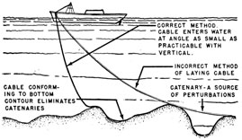
When the cable is laid, great care must be taken
to provide the proper tension on the cable as it is
paid out. If too much tension is kept on the cable,
lengths of cable will be suspended between high
spots of the ocean's bottom. These suspended
portions of cable will move with the movements
of the water and limit the usable sensitivity of
the system. If the cable is laid as slack as possible
it will conform closely to the contour of the bottom,
and movement will be materially reduced. However, some tension will exist as the cable leaves the
ship because of the weight of the cable hanging in
the water. Figure 16-7 shows the effects of the
Figure 16-7. -Correct and incorrect methods of laying
submarine cable.
correct and incorrect methods of laying submarine
cables.
Discriminator
In most magnetic-loop systems the maximum
sensitivity of the fluxmeter cannot be realized because of interference caused by cable movement.
For example, if a 10-foot length of cable moves 1/6
inch, the recorder pen is deflected far enough from
the movement of the cable to be confused with a
target ship. Because the frequency of interfering
signals caused by cable movement is much higher
than the frequency of signals caused by a ship
passing over the loop, it is possible to construct a
filter that removes the unwanted signals caused by
loop movement, yet does not interfere with those
from a ship. The discriminator has this function.
The discriminator consists essentially of two
circuits, or channels, as follows:
1. A filter circuit, which passes frequencies of
from 0 cycles per second (d-c) to 0.03 cycles per
second. This circuit is made up of a filter network
and a two-stage amplifier with a gain of slightly
more than one. A limiter and an output stage are
also included by which the output of the discriminator can be controlled so that the recorder pen
does not exceed the limits of the recorder tape.
2. A limiter circuit which operates the recentering
relay of the fluxmeter recorder to recenter the
galvanometer. This circuit is required because
the output of the filter circuit is so delayed that the
galvanometer coil would be out of control if the
usual centering action operated by the pen controls
were in effect. This circuit can be adjusted to
operate the recentering relay of the recorder at any
desired deflection of the fluxmeter galvanometer,
applying a return voltage to the galvanometer coil.
289
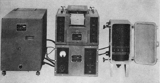
Figure 16-8.-Discriminator OS fluxmeter, recorder, and junction box.
Figure 16-8 shows the external appearance of a
discriminator with the OS fluxmeter and recorder.
The fluxmeter and recorder are devices to convert the minute changes in loop current to deflections of the pen in the recorder. The fluxmeter
is mounted on a concrete block so that vibrations
are not transmitted to the very sensitive galvanometer movement.
Multiturn Loops
From time to time the use of multiturn magnetic
detection loops has been suggested for obtaining
greater sensitivity. The suggestion is based on
the fact that the size of a signature (the trace left
by a passing ship on the recorder) increases in proportion to the number of turns used in the loop.
However, there are relatively few locations where
any real gain in sensitivity can be obtained by this
means. In many locations the fluxmeter, on even
a single turn loop, cannot be operated at its maximum sensitivity because of the perturbations due
to cable movement or other causes. With multiturn loops these cable movements are increased
in the same ratio as the ship signatures so that the
signal-to-noise ratio, which is the usual limiting
factor, is not changed.
CABLE-CONNECTED HYDROPHONES
The cable-connected hydrophone system is designed to pick up underwater sound noises from
ships and to convert them into electric impulses.
These impulses are transmitted by cables to shore
equipments where they are amplified and monitored by an operator.
Tests have shown that hydrophones should be
spaced no farther than 1,000 yards apart in a line
across the channel to be protected. With this
spacing, at least one of the hydrophones can be
depended upon to pick up the sounds produced
by a slowly moving submarine even if it is in the
presence of a noisy surface vessel. The hydrophones are usually not placed at depths of more
than 400 feet, but they will withstand pressures
at depths up to 925 feet.
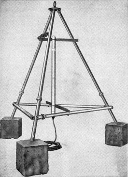
Hydrophone Assemblies
The tripods are approximately 8 feet on a side
and 8 feet high and are constructed of extra-heavy
1 ½-inch iron pipe. They are designed to hold the
hydrophone in a vertical position with the bottom
of the hydrophone approximately 1 ½ feet above
the base of the tripod. Each foot of the tripod
consists of a 1-foot cube of concrete weighing
approximately 200 pounds. A hydrophone is
shown in figure 16-9.
The hydrophone itself is approximately 55
inches long and 2 ½ inches in diameter. It comprises a long skeleton-like steel cylinder within
which are supported eight crystal assemblies at
6-inch intervals. One end of the cylinder is
closed by a watertight barrier, through which extend two insulated leads. The remainder of the
cylinder is enclosed in a rubber jacket, and the
entire unit is filled with castor oil.
Several hydrophones are placed in a line with
relays at each hydrophone to connect it to the
transmission cable when the system is used for
listening to each one individually. A maximum
of 20 hydrophones has been established for any
one line, even though not more than seven on one
line are recommended because the listening cycle
would be too long.
An automatic-manual switching unit was designed to permit the automatic scanning of a line
of 20 hydrophones, each one in succession. In
this type of equipment automatic operation may
be cut out at any time by manually operating one
of the keys provided for that purpose. There is
one 3-position key for each two hydrophones with
the center position as normal. With all keys in
the normal position, the switching is performed
automatically.
If it is desired to listen to one particular hydrophone for a longer interval of time than permitted
by automatic operation or not to wait until its
regular turn in the automatic scanning, the key
with the number of that hydrophone above or
below it may be operated in the direction of the
number desired. Odd numbers with indicator
lights for each appear above the keys. Even numbers with indicator lights are below the keys.
For example, if it is desired to stop automatic
switching and connect No. 4 hydrophone through
to the amplifier, the second key from the left
should be moved to the down position. Other
equipments may have rotary-type selector
switches.
The hydrophone listening equipment, therefore,
can be used in such a manner that the operator
can listen to each of the hydrophones in succession
automatically, or he may select any particular
unit, to localize or confirm a contact.
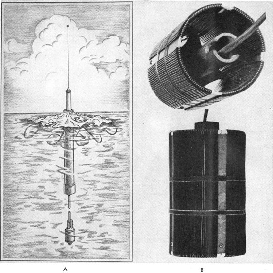
RADIO SONOBUOYS
The radio sonobuoy is used for the same purpose
as the cable-connected hydrophone. Fundamentally, the radio sonobuoy comprises a buoy barrel
containing a medium-powered f-m transmitter,
an antenna for transmission of the radio wave, a
suspended crystal hydrophone, and a separate
battery float and anchor.
In practice, the buoys are generally immediately behind the loops for the purpose of localizing
the point at which one of the loops has been
crossed. The buoys should not be spaced farther
than 1,000 yards apart, as in the case of cable-connected hydrophones. Radio sonobuoys generally are used when there is not sufficient time
for the installation of the necessary cables for the
cable-connected systems, or when the water is too
deep to allow placing of the cable-type hydrophones.
Model JM-4 Radio Sonobuoy
Function.-The purpose of the model JM-4
radio sonobuoy is (1) to detect underwater sounds
291
produced by moving power-driven watercraft and
(2) to transmit these sounds to a shore-listening
station as a warning that a craft is moving in the
waters within range of the buoy. Under normal
conditions, a radio sonobuoy can detect a vessel
underwater at ranges of about 1,500 to 2,000
yards. The buoys are spaced 1,000 yards or less
apart to assure satisfactory coverage under
unfavorable water conditions.
A receiver on shore-up to 19 miles from the
most distant buoy-picks up the signal from the
buoy. The receiver is continually tuned either
manually or automatically, so that each buoy is
listened to at least once each minute. When a
ship's sound is picked up by a particular buoy
this buoy is selected for continued listening to
verify the presence of the vessel. If the ship's
sound is heard on more than one buoy, the
loudest buoy is assumed to be the closest to the
vessel. A report is then made to the patrol
activity that a vessel is present.
Description.-The model JM-4 radio sonobuoy
equipment is shown in figure 16-10. It consists
of an f-m transmitter contained in a buoy,
powered by a large dry battery in a steel container
supported in a toroid-shaped buoy. A hydrophone is suspended below the transmitter buoy
by a suitable length of cable. The battery buoy
is anchored, and the transmitter buoy is connected
to it with a tie rope.
The transmitter buoy consists of a 53-gallon
steel barrel, to which a cover, a tower and antenna
assembly, and a tail pipe are secured. The
transmitter is attached to the bottom of the
cover of the buoy in such a manner that the
radio equipment may be removed from the
barrel by removing the cover. The tail pipe,
which is weighted at the bottom to stabilize the
buoy in a vertical position, is removable to
facilitate handling and storage of the equipment.
The hydrophone is connected to the transmitter
through its cable and a watertight connector
located on the top of the buoy cover. This
hydrophone, consisting of two sound-sensitive
Rochelle-salt crystals, is suitably encased in a
metal housing protected by a sound-transparent
rubber sleeve.
Battery voltage is applied to the transmitter
through a length of cable from the battery and a
second watertight connector located on the top
of the buoy cover and diametrically opposite the
hydrophone connector. The battery cable follows the side of the transmitter buoy through two
securing cable clamps and then is suspended in
the water until it reaches the battery buoy. This
cable is secured to the side of the transmitter
buoy. The termination of the cable at the battery
buoy is similar to that at the transmitter.
The battery buoy consists of eight drums
welded around a larger battery container, in
which the battery is sealed.
The buoy is suitably anchored and the transmitter is secured to it by lengths of wire rope.
The schematic diagram of the JM-4 sonobuoy
transmitter is shown in figure 16-11. The r-f
oscillator tetrode V105 is frequency modulated
by triode V104 acting as a reactance modulator.
Pentodes V101 and V102 comprise two resistance-coupled amplifier stages preceding the reactance
tube.
The transmitter operates at any frequency in
the range of from 70 to 90 megacycles. It is
frequency-modulated and has an undistorted
modulation width of ±75 kilocycles. The transmitter is provided with pre-emphasis so that the
frequencies between 600 and 12,000 cycles per
second are emphasized, while signals of other
frequencies are amplified with lesser gain. The
purpose of this pre-emphasis is to increase signal-to-noise ratio between 600 and 12,000 cycles per
second because most of the useful frequencies
are in this range. The audio range of the transmitter extends to 18,000 cycles per second.
The output circuit of the transmitter is coupled
to a concentric line which feeds a quarter-wave
ground-plane type of antenna.
The transmitter frequency and the modulation
level are adjustable by means of two tuning controls and one level control, all of which are located
on the top of the cover of the transmitter buoy.
The r-f output is sufficient to operate over distances of more than 10 miles-depending on the
sensitivity of the receiver and the type of antenna
installation-at battery voltages as low as 200
volts.
The battery is of the dry cell type, and is designed to operate the transmitter for a continuous
period of approximately 3 weeks, after which it
should be replaced with a fresh battery.
are that they are subject to damage by vessels colliding with them, they are likely to capsize and be
put out of operation when the antenna becomes
coated with ice, and they require frequent battery
changes. The batteries are heavy and sometimes
create a logistic problem.
On the other hand they can be installed quickly
and easily in any depth of water, and they do not
necessitate the long task of cable laying.
HERALDS
As previously stated, the herald is the most precise of the underwater sound detection devices, in
that with it the operator is able to obtain exact
bearings and ranges with the equipment. This information enables him to determine accurately the
position of the target.
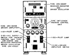
Model QBH Herald
The QBH herald equipment consists of a shore-station cabinet (figure 16-12), and a water-station
unit (figure 16-13). The shore-station cabinet contains a receiver, a transmitter, and operating and
training circuits. This console is connected by
submarine cable to the water-station unit, which
contains a crystal transducer and means for rotating and tilting the beam. The equipment operates from a 115-volt 60-cps source and requires
about 700 watts.
The shore-station unit has three chassis. The
bottom chassis, called the driver-amplifier unit,
contains power amplifiers and rectifiers. The
center chassis, called the training-control unit, contains training controls and indicators for the bearing
and tilt of the beam. The top chassis, or receiver-indicator and driver-oscillator unit, contains
receiver circuits, a range indicator, and a driver
oscillator. Two range scales are provided-0 to
1,000 yards and 0 to 4,000 yards, with alternate
keying provisions. The effective ranging capability of the equipment is about 4,000 yards. The
duration of the ping is about 250 milliseconds (200
yards) on the 4,000-yard scale and 95 milliseconds
(75 yards) on the 1,000-yard scale. A short ping
of 30 milliseconds also is available for use on the
1,000-yard scale.
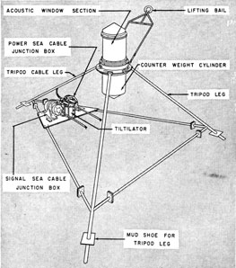
The water-station unit is located on the sea bottom. The watertight cylindrical housing is filled
with castor oil. The crystal transducer, located
at the top of the upper cylindrical housing, projects
a beam of ultrasonic energy downward to a metallic
plate, or acoustic mirror. The mirror is positioned
by step motors to rotate or tilt the beam. These
motors are located below the mirror in the lower
part of the cylindrical housing.
The water-station unit can be located up to 5
miles offshore and at a depth not exceeding 300
feet. The location selected should be such that
(1) the beam is unobstructed, (2) the tripod does
not tilt more than 15°, and (3) the unit does not
settle excessively.
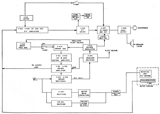
The circuits of the equipment are very similar
to shipboard echo-ranging equipment, as is the
operation of the equipment. A block diagram of
the QBH herald equipment is shown in figure 16-14.
Submarine Cables
INTRODUCTION
The installation of shore-operated harbor-detection equipment necessitates the use of a large
quantity of submarine cables. The cost of the
cable required usually exceeds that of the associated equipment, and the installation and maintenance of the cable require considerable skill.
The efficient functioning of the cable system
depends on (1) the selection of cable of suitable
design, (2) proper care and handling of the cable
and of the associated underwater equipment during
laying operations, (3) well-made cable splices,
and (4) correct testing and maintenance procedure. Therefore, it is of the utmost importance
that all personnel responsible for the installation
and maintenance of harbor-detection equipment
should become thoroughly familiar with standard
submarine-cable practice.
The sole function of a submarine cable is to
transmit electric currents underwater with the
greatest possible efficiency. The core designs selected vary greatly, depending on the voltage,
current, and frequencies to be transmitted and
on the number and kind of circuits required. In
addition to the core, protective coverings must be
added (1) to protect the cable from abrasion and
damage by the sea, and (2) to impart sufficient
tensile strength to permit handling. These coverings
293
Figure 16-12.-Shore-station cabinet of the QBH herald
equipment.
also vary considerably, depending on the conditions encountered. Therefore, most submarine
cables are manufactured to meet the specific
requirements of individual customers.
Although individual designs vary, several well-established design techniques usually are followed.
Hence, most cable designs are merely suitable
combinations of standard components, assembled
to produce a cable with the required characteristics.
Submarine cables may be divided broadly into
two classes-sheathed and nonsheathed. In the
former class the core is enclosed in a watertight
lead sheath, thus permitting the use of a non-waterproof material like paper for insulating the individual conductors. In the latter class the lead
sheath is omitted and the conductor insulation is
of some material-such as rubber or thermoplastic
compound-that retains its insulating properties
when exposed to moisture.
Lead sheaths are easily damaged or cracked
when subjected to rough handling or continuous
motion caused by waves, and consequently they
are used ordinarily only in sheltered waters. As
underwater-detection cables frequently are laid
under adverse conditions, lead sheaths and paper
insulation are not deemed sufficiently reliable.
Therefore, these instructions deal exclusively with
cables of the nonsheathed class.
Most nonsheathed cables consist of the required
number of conductors, individually insulated with
rubber or thermoplastic compounds and suitably
taped or braided. These insulated conductors are
laid up spirally, filled, and taped to form a round
core. In some cables a rubber or thermoplastic
jacket is applied over this core. Although such
jackets are essentially waterproof, jacketed cables
are not considered to be in the sheathed class because minute amounts of water may in time
penetrate the jacket, making the use of waterproof insulation on the individual conductors advisable. Jute or other bedding usually is applied
over the taped or jacketed core; steel-wire armor is
then laid on spirally for mechanical protection;
and a final layer of jute, coated with tar and
asphalt, is added to reduce corrosion.
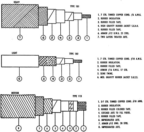
TYPES
Harbor detection cables can be divided into
three classes-(1) magnetic loop cables, (2) herald
cables, and (3) hydrophone cables.
Several types have been designed for each class,
depending on their function and the conditions
under which they are installed.
Figure 16-15 shows three submarine cables-
types 101, 102, and 113.
Figure 16-13. -Water-station unit of the QBH herald
equipment.
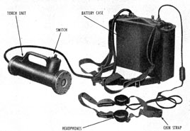
The model QAA equipment (figure 16-16) is a
portable f-m sonar device that gives a qualitative
indication of direction and distance of objects
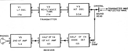
within a range of about 5 to 75 feet. A block
diagram of the equipment is shown in figure 16-17.
The low-frequency oscillator varies the frequency
of the high-frequency oscillator. The output of
the high-frequency oscillator then is applied to a
quartz-crystal transducer, which sets up ultrasonic waves in the water. A portion of the transmitted sound wave is reflected by the object, and
on striking the quartz-crystal transducer it generates a voltage, which is applied to a detector. The
equipment uses a single crystal for transmitting
and receiving. A small amount of the output of
the high-frequency oscillator also is applied to the
detector. The audio beat-frequency output of the
detector is amplified through two stages and then
applied to the headphones.
The frequency of the detector output depends
on (1) the rate at which the high-frequency oscillator frequency is changed and (2) the distance to
the object. The shorter the range to the target,
the lower is the frequency of the beat note, because
less time is required for the transmitted wave to
be reflected back to the detector. Hence the
nearer the oscillator frequency will be to that of
the reflected wave at the time it is received.
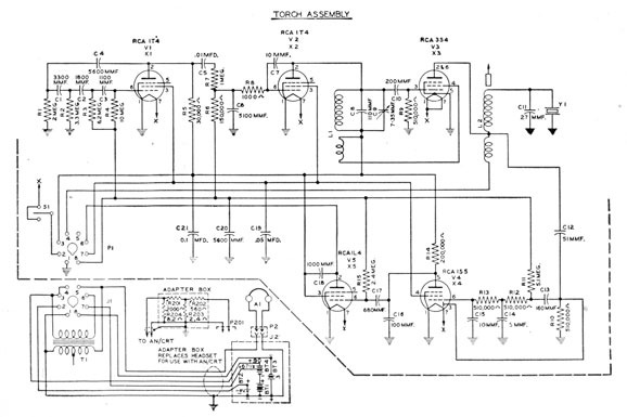
CIRCUIT
Figure 16-14. -Block diagram of QBH herald equipment.
295
Figure 16-15 -Submarine cables, types 101, 102, and 113.
The first tube, V1, is the low-frequency oscillator. It uses a resistance-capacitance feedback
network to produce a frequency of 12 cycles per
second. This frequency is used to sweep the
high-frequency oscillator.
Tube V2 is a conventional reactance tube
modulator. The high-frequency voltage from
tank, Ll, is fed back to the grid of V2 by a 10
μμf capacitor. A high-frequency current will
flow through C7, R8, and C6 to ground. This
results in a voltage across R8 and therefore on the
grid of V2 which is in quadrature with the tank
voltage. V2 plate current will therefore be in
quadrature with the tank voltage and the effect
is that of a capacitor in parallel with the tank.
This tube current, and hence the effective capacitance, is varied at a 12-cps rate by the signal from
V1. Thus, the resonant frequency of the V3
oscillator tank is varied. The frequency varies
Figure 16-16 -Model QAA portable sonar equipment.
296
Figure 16-17 -Block diagram of the QAA portable sonar equipment.
over a range of 5,000 cycles per second above and
below the average frequency.
Tube V3, the high-frequency oscillator, is a
typical electron-coupled oscillator. The plate
circuit, which is isolated from the grid circuit by
the screen grid, has only a minor effect on the
frequency. The reactance tube, V2, is connected
across the frequency-controlling portion of the
Figure 16-18 -Schematic diagram of the QAA portable sonar equipment.
297
Figure 16-19. -AN/CRT-1A radio sonobuoy and hydrophone. A, Transmitting position; B, hydrophone.
circuit and varies the frequency in accordance
with the signal from the low-frequency oscillator.
The plate circuit produces a high voltage across
the quartz crystal. The oscillator normally
operates at an average frequency of 500 kilocycles.
Tube V4 is a combination detector and first
audio-frequency amplifier. The detector is a
diode. The network of resistors and capacitors
(RIO, R12, R13, C14, and C15) between the
diode plate and the control grid is a filter to suppress high frequencies in the detector output.
Tube V5 is the audio output tube. The audio
output is coupled to the phones through a
transformer.
298
Submarine Detection by Aircraft
Antisubmarine warfare is a vital part of the
defense problem, and the detection of submarines
by aircraft is a high-priority phase of the antisubmarine problem. Although radar is the basic
detection device for surface vessels, it is ineffective
against submerged submarines. In World War
II, two devices were developed and used by aircraft for the detection of submerged vessels. These devices are the radio sonobuoy and the
magnetic airborne detector (MAD).
TYPE AN/CRT-1A RADIO SONOBUOY
The AN/CRT-1A, designated ERSB (Expendable Radio SonoBuoy), is an expendable device
that is dropped from airplanes or blimps by means
of a small, self-contained parachute. It is used
to pick up the underwater sounds of submarines
and transmit them to the aircraft by radio. The
ERSB is made up of (1) a cylindrical magnetostriction hydrophone and (2) an amplifier connected to an f-m radio transmitter. The sonic
hydrophone, amplifier, and transmitter, together
with a battery power supply, are incorporated in
a waterproofed cardboard tube about 30 inches in
length and 4 inches in diameter and weighing
about 12 pounds. The transmitter and batteries
Figure 16-20. -Interior view of the AN/CRT-1A buoy.
housed in an upper compartment, which is
separated by a watertight bulkhead from the
release mechanism, hydrophone, and cable in the
lower compartment.
The transmitter operates on frequencies between
67 and 72 megacycles and has a maximum range
of about 35 miles when the aircraft is at an altitude
of 5,000 feet. The device has an operating life of
from 2 to 4 hours after planting. After this
period, a carbowax plug dissolves and permits the
buoy to sink. In order to track a moving submarine, several buoys may be dropped in a pattern
surrounding the known or suspected location of
the submarine. A receiver, designated by type-number AN/ARR-3, is carried in the aircraft.
The receiver has as many as 12 channels corresponding to the frequencies of the buoys. A high
degree of automatic-frequency control compensates for any lack of frequency stability in the
buoys.
A wooden cap, fitted with a rubber gasket and
clamping screws, seals the top of the tube and
serves as a mounting for the antenna and parachute
assembly. This cap also contains the carbowax
plug, to flood the mechanism at the end of its
life. Four holes are cut through the wall at the
upper end of the lower compartment to ensure
flooding and to provide a cushioning effect by
regular air release as the buoy strikes the water.
The bottom of the housing terminates in a
cast-metal ring, which aids in stabilizing the buoy
in the water and which provides a mounting for
the hydrophone release mechanism. This mechanism consists of a spring arrangement, which
holds the hydrophone firmly in place during
shipping and handling but which automatically
triggers on impact with the water and permits
the hydrophone to drop to the limit of its 24-foot
cable, as shown in figure 16-19, A. The hydrophone, figure 16-19, B, is a cylindrical magnetostriction unit that is wound on a nickel shell. Its
construction permits the storing of the cable inside
the hollow shell and effects a reduction in length
of about 4 inches compared with earlier models.
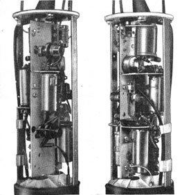
Two photographs of the AN/CRT-1A transmitter are shown with the cover removed in
figure 16-20. The r-f side is shown at the left
and the a-f side at the right.
299
Figure 16-21 -Schematic diagram of the AN/CRT-1A.
The f-m transmitter utilizes five vacuum tubes,
which provide approximately 90 db of audio-voltage gain and an effective r-f antenna radiation
of about 0.1 watt. Frequency modulation was
used in preference to amplitude modulation for
three main reasons: (1) the signal-to-noise ratio,
which is considered of vital importance because
the receivers are always used in close proximity
to aircraft engines, is better for frequency modulation; (2) frequency modulation provides precise
automatic control of volume of all signals sufficiently strong to fall within the effective operating
range of the receiver; and (3) frequency modulation reduces the effects of interference between
two buoys of the same frequency. This interference exists when extra buoys are dropped
while tracking, and before the original buoys have
ceased operating.
The AN/CRT-1A transmitter is mounted on a
single rectangular plate, with the audio amplifier
and the reactance tube on one side and the r-f
circuit on the other. The mounting provides
compactness and improved isolation between the
a-f and r-f circuits.
300
Figure 16-22 -AN/ASQ-1 MAD equipment.
Freedom from microphonic noise is achieved by
use of (1) four shockproof rubber mountings for
the chassis plate and (2) separate rubber mountings for each tube socket. The whole transmitter
assembly is enclosed in a transparent acetate tube
for protection when the unit is withdrawn from the
housing for installation of batteries.
The battery assembly consists of four parallel-connected standard 1.5-volt flashlight cells for
filament voltage, and two series-connected 67.5-volt miniature batteries for plate voltage. Sufficient battery capacity is available for a continuous
operating life of about 4 hours.
239276°-53-20
The antenna is a 39-inch telescoping quarter-wave tube mounted on the buoy housing cap.
About 9 ½ inches of the antenna are enclosed in a
watertight insulating sleeve to avoid short-circuiting
by waves. The antenna is coupled to the r-f
amplifier tube by a tuned circuit. This tuned
circuit matches the impedances of the antenna and
transmitter and helps to stabilize operation by
isolating the tuned transmitter circuits from the
direct influence of any variations in antenna
characteristics due to motion of the buoy.
The parachute is 24 inches in diameter and is
orange-dyed. After the buoy is launched, the pack
301
Figure 16-23. -Magnetometer of the AN/ASQ-1.
cover is torn loose by a static line attached to the
plane. The antenna protrudes through a hole in
the chute, and the pull on one of the shrouds withdraws a switch pin and turns on the transmitter.
On reaching the water, the parachute settles about
the antenna base.
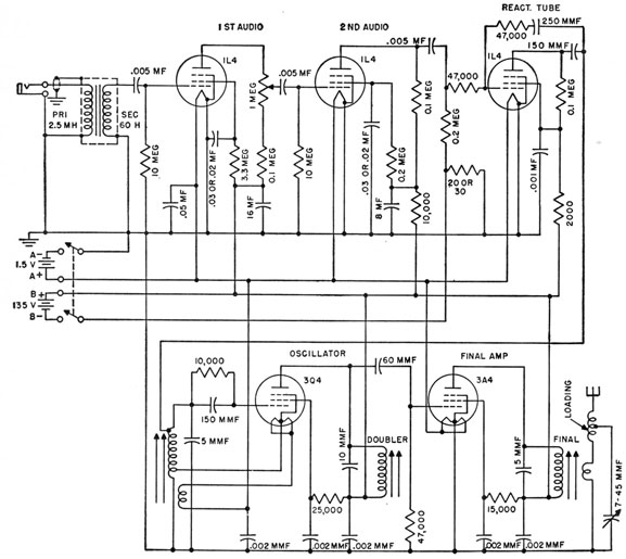
The schematic diagram of the AN/CRT-1A is
shown in figure 16-21. The oscillator is frequency-modulated by the reactance tube. The reactance
tube is driven by two audio-amplifier stages.
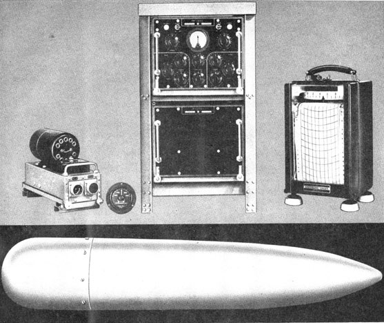
MAGNETIC AIRBORNE DETECTOR
One of the ASW devices developed and used in
World War II was the magnetic airborne detector
(MAD). Detection equipments AN/ASQ-1, AN/
ASQ-1A, AN/ASQ-3, and AN/ASQ-3A were installed on naval airplanes and airships. The
AN/ASQ-1 equipment is shown in figure 16-22.
The MAD equipment uses a magnetometer,
which is a saturable inductor. The magnetometer
(figure 16-23) is a coil of wire wound on some high
permeability core such as permalloy. A d-c current
is passed through the coil to balance out the earth's
magnetic field. The core therefore is in zero field.
The inductor is energized by a pure 400-cps
sine-wave current (for the AN/ASQ-1 and AN/
ASQ-1A) or a pure 1,000-cps sine-wave current
(for the AN/ASQ-3 and AN/ASQ-3A). The
current saturates the core on both positive and
negative swings. As the magnetometer is in zero
magnetic field, the core is saturated equally on
both positive and negative swings, and only odd
harmonics of the exciting signal appear at the
output. However, when the magnetometer enters
a magnetic field, the operating cycle is not the
same on both positive and negative swings, and
even harmonics appear at the output.
In the AN/ASQ-3 equipment, a band-pass filter
separates the 2,000-cps second harmonic that is
produced when the magnetometer element enters
a magnetic field such as that which might be
produced by a submarine. This signal is amplified
and recorded on a recorder.
In an airplane or airship the magnetometer
element is mounted so that it is as far as possible
from the field of the ship. The detector element
can be mounted on (1) the end of streamer cable,
(2) a wingtip, (3) a "stinger" tail, or (4) the bag
of an airship.
Provisions are made for stabilizing and orienting
the sensitive element around two axes. This
element is in a gimbal mounting, and two
gimbal
motors are used to position the element.