Methods of Drying and Charging Optical Instruments, OD 2847, 1944, describes how to dry and charge with nitrogen or helium optical instruments.
In this online version of the manual we have
attempted to keep the flavor of the original layout while taking advantage
of the Web's universal accessibility. Different browsers and fonts will cause
the text to move, but the text will remain roughly where it is in the original
manual. In addition to errors we have attempted to preserve from the original
this text was captured by optical character recognition. This process creates errors that are compounded while encoding for the Web.
Please report any typos, or particularly annoying layout issues with the Mail Feedback Form for correction.
Part III - Charging and drying submarine periscopes
13
O.D. 2847
15 Sheets
Sheet No. 3
Illustrations:
Drawings 119231
N.G.F. Negatives 30608
154856
30609
233249
233250
243589
320308
267634
INTRODUCTION
1. The fogging of optical instruments is due to the condensation
of water vapor on the optical elements. There are two types of fogging; external and internal. External fogging is temporary, and can be readily identified and easily eliminated. Internal fogging is of a most serious nature and its elimination requires skilled technique and special equipment.
2. External fogging can take place on the outside of the rear eyelens or eyepiece window and on the objective or objective window whenever the temperature of the glass is lower than the dew-point of the air to which it is exposed. A temporary fogging at the eyepiece may occur as a result of moisture in the observer's breath or, as in the case of submarine periscopes, at times when the periscope is first raised after it has been housed in the cold periscope well for a long period and the air in the submarine happens to be particularly humid. The condensation or fog that forms on the outside of the eyepiece can be wiped off with lens paper and the fogging will cease when the instrument becomes warmer. External fogging of the objective window will rarely occur. However, in the case of submarine periscopes, it is possible and may occur when the temperature of the sea water is appreciably colder than the dew-point of the outside air. This type of fogging can be recognized by the fact that when the periscope is first raised clear of the water and the outside surface of the window is still wet there is no apparent fog, but as the surface dries condensation slowly appears. This can be rapidly eliminated by occasionally lowering the periscope and wetting the window.
3. Internal fogging is due to the presence of sufficient moisture or water vapor, within the instrument, which condenses on one or more optical surfaces whenever the temperature of the optics falls below the dew-point. Obviously, the most practicable remedy of this situation is to reduce the moisture or water vapor to a point where condensation cannot take place at any temperature met by the instrument in service. In most instruments this is accomplished by periodic recharging with dry ges. To accomplish this in submarine periscopes it is necessary to evacuate the assembled periscope to a very low absolute pressure and then recharging with dry nitrogen.
4. This O.D. is prepared to give the necessary information and instructions for drying and charging optical instruments.
O.D. 2847
15 Sheets
Sheet No. 4
PART I
CHARGING WITH DRY GAS OR NITROGEN
1. As to the frequency with which optical Instruments should be recharged, the following procedure Is recommended for optical repair activities for those instruments fitted with charging systems:
(a) Recharge optical instruments prior to the conclusion of each overhaul of a vessel alongside of tender repair ship if recharging of the instrument has not been accomplished during the preceding six months.
(b) Recharge optical instruments prior to the departure of a vessel from a Navy Yard upon completion of a regular Navy Yard overhaul if a recharging has not been accomplished during the preceding six months.
(c) Recharge optical instruments at the earliest practicable date after need therefor is discovered as a result of inspection by ship's force or personnel of optical repair activities.
(d) The interval of time between successive rechargings of optical instruments should not exceed twelve months.
2. Apparatus and Procedure.
Three types of portable dryers - Optical Instrument Dryers Marks 1, 2 and 3, are provided for use in drying and recharging. The higher the temperature at which drying and charging are conducted, the more thorough will be the drying of the instrument. It is advisable not to recharge optical instruments in temperatures below 32°F.
OPTICAL INSTRUMENT DRYER MARK 1
3. This dryer provides means for drying the interior of an optical instrument by evacuating the air from the instrument. The dryer consists of the ejector and vacuum gage, shown on drawing 154856, and two pieces of hose about three feet long for connecting these units. The gage is provided with a knob and air valve connector for securing to the air inlet valve in the optical instrument. The threaded end of this connector is 1/4"-24 threads while the tapped hold in the air valve (piece 1 drawing 119231 or pieces 2 or 3 drawing 267634) of the optical instrument is 1/4"-28 threads. An adapter must, therefore, be made for this connection.
O.D. 2847
15 Sheets
Sheet No. 5
4. Operation of Dryer Mark 1.
(a) Secure the gage to the air valve in the instrument which is to be dried. Connect one hose to the gage and to the ejector nozzle marked "to instrument". Connect the other hose to the ejector nozzle marked "to tank" and to the ship's low pressure air line. Set the ejector valve to "vacuum" and open the valve in the air line so that air blows through the ejector. Adjust the regulator valve to obtain a pressure of about 18 pounds.
(b) Open the air inlet valve in the optical instrument so that the air or gas in the instrument may be exhausted. Continue the flow of air through the ejector until the gage registers about 22 inches of vacuum. This should take about 25 minutes, after which the air valve in the optical instrument should be closed in order to retain this partial vacuum while making the necessary connections for recharging.
(c) Before recharging the optical instrument with nitrogen or compressed air, disconnect the hose from the ship's air line and connect it to a nitrogen bottle or compressed air tank.
(d) Open the reducing valve on the nitrogen bottle or compressed air tank and allow the gas or air to escape slowly through the ejector. Open the air inlet valve in the optical instrument. Set the ejector valve to "slow filling" and allow the instrument to fill until the gage shows only a few inches of vacuum. Then set the ejector valve to "fast filling" and when the gage shows 2 pounds pressure, close the inlet valve in the instrument.
OPTICAL INSTRUMENT DRYER MARK 2
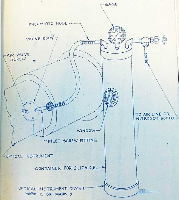
5. This dryer provides means for drying an instrument by forcing dry air or nitrogen through the instrument. The dryer consists of a container filled with silica gel, a gage and fittings, as shown on plate I and drawings 233249 and 233250. A window is provided in the side of the container for examining the color of the silica gel. The silica gel must have the wet and dry indicating feature. This silica gel contains cobalt chloride (Co CL2) and can be obtained from the Davis Chemical Company of Baltimore, Maryland. The color of this silica gel is pale blue when dry and pink when wet. When the color has changed to pink the silica gel must be removed from the container and baked, after which it should again be placed in the container for
O.D. 2847
15 Sheets
Sheet No. 6
further use. Either the ship's low pressure air line, nitrogen bottle or compressed air tank may be used with this dryer.
OPTICAL INSTRUMENT DRYER MARK 3
6. This instrument is similar to Optical Instrument Dryer Mark 2 differing from it only in minor details, see drawing 320308.
7. Operation of Dryer Mark 2 or Mark 3 (See Plate I)
(a) Connect the outlet of the nitrogen bottle or air line to the inlet connection of the silica gel container by means of a suitable host.
(b) Connect the outlet valve of the silica gel container to the air inlet valve of the optical instrument which is to be dried.
(c) Back off the inlet valve screw, piece 4 drawing 119231 or piece 4 drawing 267634, in the air valve body of the optical instrument and also open the air outlet valve of the optical instrument. This latter valve is usually located at the opposite end of the instrument from the air inlet valve and in some instruments is simply a screw with a lead washer.
(d) Hold the thumb over the air outlet in the optical instrument and open the control valves in the gas or air lines. When the gage shows a pressure up to, but not exceeding, five pounds remove the thumb from over the outlet, allowing the gas or air to escape. At about five minute intervals, over a period of approximately on half hour, repeat the operation of applying a slight pressure of gas or air in the instrument, then allowing the gas or air to escape. The outlet valve should then be closed and the instrument allowed to fill with gas or air until the pressure is approximately two pounds. The inlet valve is then closed and the dryer disconnected from the instrument.
O.D. 2847
15 Sheets
Sheet No. 7
PLATE I
O.D. 2847
15 Sheets
Sheet No. 8
PART 2
CHARGING RANGEFINDERS WITH HELIUM
1. Optical instruments are not to be charged with helium except on specific authorization or direction of the Bureau of Ordnance. The purpose oF the use of helium as a charging agent is to reduce the stratification effect in rangefinders when used for ant-aircraft work. Only anti-aircraft rangefinders of a base lengths greater than 1-1/2 meters are to be charged with helium.
2. When charging rangefinders with helium the Mark 2 or the Mark 3 dryer should be used. The arrangement of the charging outfit is shown on N.G.F. Neg. 30608. It is considered that an instrument requires recharging when the concentration as measured by a Helium Purity Indicator drops below 80%.
3. Procedure to be followed in Charging Rangefinder with Helium is given below: NOTE: This work is to be performed only by qualified optical repair personnel.
(a) Attach the reduction valve to the helium bottle by means of the thread adapter, (to be made by Navy Yards or forces afloat to suit connection on helium bottle).
(b) Clear out all hose with dry clean air before connecting.
(c) Remove caps from the air inlet and outlet valves of rangefinder, where caps are provided.
(d) Connect the pressure reduction valve to the silica gel container of the dryer by means of the pneumatic hose, and open the valve on the dryer.
(e) Connect the dryer to the inlet valve body of the rangefinder.
(f) Remove the screw plug from the air outlet valve body.
(g) Connect the Helium Purity Indicator to the air outlet valve. (See N.G.F. Neg. 30609)
(h) Turn the handle on the reduction valve counterclockwise to insure that the valve to the low pressure gage. is closed.
(i) Turn on the gas by turning counterclockwise the handle of the valve on the helium bottle. Record the pressure and cubic feet of the helium as read on the high pressure gage.
(j) Open the charging valve on the rangefinder by unscrewing part way the air valve screw.
O.D. 2847
15 Sheets
Sheet No. 9
(k) Slowly turn on the gas at the exit valve of the reducer, by turning the handle clockwise. The pressure as read on the low pressure gage must not exceed one pound.
(l) Immediately open the outlet valve of the rangefinder, by unscrewing part way the air valve screw. These valves must be open to their full extent during charging. The Helium Purity Indicator then measures the percentage of helium in the mixture leaving the rangefinder.
(m) Increase the pressure on low pressure gage to 5 lbs. and maintain at that pressure while running sufficient helium into the rangefinder to bring the concentration to 96 to 98% as determined by the Helium Purity Indicator.
(n) When the desired concentration of 96 to 98% has been reached, close the exit valve in the rangefinder.
(o) Adjust internal pressure within the rangefinder to 1 to l-1/2 lbs. per sq. in. Close the entrance valve in the rangefinder. Close the exit valve of the reducer.
(p) Close valve on helium bottle by turning the valve handle clockwise.
4. In the event a purity indicator is not available the charging of the rangefinder must be done cautiously so as not to waste the helium. In this case rangefinders of base length greater 2-1/2 meters should be gassed for a period of approximately 20 seconds at a pressure of 5 lbs. gage.
5. If the rangefinder has not previously been charged with helium paint a bright yellow circle near the charging valves on the top of the air valve screw in the charging valve body. This will serve to indicate that the instrument is charged with helium.
O.D. 2847
15 Sheets
Sheet No. 10
Parallax in AA Rangefinders Resulting from Use of Helium as Charging Agent
6. The data in sections 7 and 8 are taken from Naval Gun factory letter C-N0s-80352(142), (T,L) of 31 October 1942 and are recorded herein for the information of repair activities. In Table I are shown calculated values of parallax between target image and reticle, in diopters at the eyepiece, to be expected when helium is introduced in various rangefinders which have previously been adjusted for nitrogen or air. Also included in the table are the corresponding distances which the objectives of the several rangefinders must be moved toward the reticle in order to remove this parallax.
7. The computations were based on the lens data given on drawings available at the Naval Gun Factory for the various rangefinders, using the refractive indices, Nd = 1.0002935 for air and Nd = 1.0000349 for helium (both at 760 mm of hg. pressure and 0° C. temperature). Sample calculations indicated that the decrease in focal length of the erecting system, when surrounded by helium, should be neglected for practical purposes in all the rangefinders. No allowance was made in the computations for the change of refractive index of air and helium with pressure and temperature. In order to check the calculations and the validity of the assumption that only the change in focal length of the objective need be considered, a Rangefinder Mark 42, Mod. 10 set for magnification 24 x was adjusted as follows:
(a) The two objectives were moved so that there was no parallax between the reticles and the images of a target 2970 yards distant, as determined with a diopterscope at the eyepieces. Parallax was then measured with the rangefinder under air pressures of 5 and 3 lb/in2, a vacuum of 22 inches of mercury, and 3 lb/in2 pressure of helium (98% concentration). The results are given in the following table in diopters et the eyepieces:
AIR
HELIUM
VACUUM
DIOPTERS
Atmos. Press. 0.0
3 lb/in2 Press. -0.25
5 lb/in2 Press. -0.4
Atmos. Press. +1.0
3 lb/in2 Press. +0.9
Calc.
+1.0
22 inches Mercury +0.8
Plus (+) reading indicates images between reticle and objective.
Minus (-) reading indicates image between reticle and erectors.
Readings correct to ± 0.15 diopter.
O.D. 2847
15 Sheets
Sheet No. 11
(b) The objectives of the rangefinder were moved toward the reticles the requisite distance by turning the adjusting rings located on the objective mounts. The proper amount of rotation of these rings was judged by noting the number of spaces between holes in the ring periphery which passed a fixed point (a hole in the lock ring) on the mounts. These relationships are expressed by the formula: Number of holes passing a fixed point = inches of required rotion of objective x threads per inch on adjusting ring x total number of holes in circumference of adjusting ring. The instrument was then sealed and parallax measured at atmospheric pressure, a vacuum of 24 inches of Hg., and at 3 lb/in2 pressure of helium (98% concentration). The diopters parallax were -1.0, -0.1 and -0.1 respectively. The results of these two experiments were in good agreement with those predicted from the calculations. This fact was especially significant since the adjustment of the rangefinder objectives was performed by two students of the Optical School who had had no special rangefinder repair training. Adjustment was accomplished by working through the objective access holes in the outer tube of the instrument, without removing the instrument from its mount. Ranges and accuracy of ranging were the same before and after the experiments were performed.
To further confirm the procedure for removing the parallax due to helium a Mark 42, Mod. 11 rangefinder, which had been received for repair, was adjusted by the regular repair crew of the optical shop following the procedure outlined above. The final results were in excellent agreement with those predicted.
8. Attention is called to the similarity of conditions, optically, obtaining in the rangefinder when under a vacuum of 22 to 24 inches of mercury, and when filled with helium At 3 lb/in2 pressure. By noting the accuracy of adjustment of the objectives when the instrument is under a vacuum, much helium can be saved, especially if there is an error in adjustment and the rangefinder must be opened again. By admitting the helium into a vacuum of more than 20 inches of mercury, approximately 15 cubic feet of the gas is needed to bring the pressure to 3 lb/in2 above atmospheric and to the required concentration.
9. It is believed that most AA rangefinders can be adjusted
to remove parallax caused by the use of helium without removing them from their mounts. Exceptions are Rangefinders Marks 38, 41 and 41 Mod. 1 since they are not fitted with objective access holes. Therefore, it is impossible to readjust these rangefinders except in an optical shop.
O.D. 2847
15 Sheets
Sheet No. 12
TABLE I
Rangefinder Data
Parallax
Objective Mount
Ordnance Drawings
Mark
Mod.
Mfgr.
Diop.
Inches
T.P.I.
Turns
Spaces between Holes {See Par. 7b}
Title
No.
38
1
B&L
1.02
0.0195
36
0.702
16.8
Obj. Mt. Assy. &Details
175909
42
0
" )
Same as Mark 38-1
42
1
" )
Same as Mark 38-1
42
2
" )
Same as Mark 38-1
42
3
" )
Same as Mark 38-1
42
7
" )
0.69
0.027
24
0.648
15.6
Obj.Mt.Assy. &Details
Mk. 45RF 176414
38*
0
K&E
0.98
0.022
16
0.352
5.6
Section at Compensator
156056
42
4
"
1.05
0.0175
16
0.280
2.24
Sectional Assembly
203045
42
5
" )
Same as Mark 42-4
"
203045
42
6
" )
Same as Mark 42-4
"
220594
42
8
" )
Same as Mark 42-4
"
272138
42
9
" )
(Serial No. 119 only)
"
272141
42
10
" )
Same as Mark 42-4
"
279359
42
11
" )
Same as Mark 42-4
"
279359
42
12
" )
Same as Mark 42-4
"
222937
41*
0+
"
0.71
0.014
16
0.224
2.24
Right End Section
169988
41*
1+
"
0.71
0.0126
16
0.202
2.0
"
189633
41
2
B&L
0.53
0.0163
36
0.587
14.0
Obj.Mt. Assy.
Mk 43RF 176277
* Entire Objective mount rotates or, adjustment - Alignment must be checked
+ No access holes to objective Mt. Optical tube must be withdrawn from outer case for adjustment
O.D. 2847
15 Sheets
Sheet No. 13
PART III
CHARGING AND DRYING SUBMARINE PERISCOPES
1. The charging and drying of submarine periscopes should, if possible, be undertaken only by personnel skilled in the maintenance and care of submarine periscopes, who have studied this procedure and are sufficiently familiar with each step.
2. This procedure can be performed with the periscope installed in the submarine except that, when the temperature is under 50°F, it is preferable that it be done ashore or on the tender to gain advantage of a higher temperature. This method consists of evacuating the periscope, using a vacuum pump, to an absolute pressure of 40mm mercury, thereby removing any significant amount of moisture present in the instrument. It is then filled with nitrogen that has been passed through a silica gel dryer and cotton filter.
3. As a preliminary step the periscope should first be tested for tightness, with nitrogen under pressure. This will avoid the extremely difficult task of locating leaks while the periscope is under a vacuum. The periscope is filled slowly, taking two hours to build up a pressure of 100 pounds gage. Strong gas currents in the periscope should be avoided at all times to prevent the deposit of dust on the optical surfaces; too rapid building up of pressure may derange the optical system. The instrument is then thoroughly checked with soap for leaks. When it has been made tight the pressure is slowly released over another two hour period.
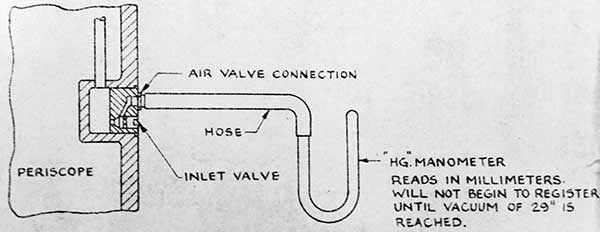
4. Prior to evacuating the periscope the pump should be checked by attaching a mercury manometer to the suction side. If operating properly the pump will pull a "flat" vacuum; that is, the height of the mercury in both legs of the manometer will equalize. Care must be taken to keep the pump level to prevent loss of oil from exhaust port.
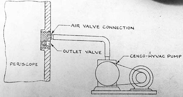
5. Connections are made for evacuating as illustrated on Plate 2. All leads should be kept as short as possible. A sealing compound should be used to insure tight joints at the periscope inlet valves and at other connections in the evacuating system. It may also be necessary to seal over the inlet and outlet air valve screws. Sealing compound should not he used on any other part of the instrument.
6. The periscope is then evacuated to 4 mm absolute; the time required will be several hours, depending on the amount of moisture present. After the pump has begun evacuation it should not be left unattended for if the pump should stop for any reason oil or oil fumes might be sucked into the periscope. When 4 mm has been attained, the outlet valve is closed before the pump is shut off to preclude possibility of pump oil being drawn into the periscope. The vacuum should then be held for a period of 3 hours as a check on the
O.D. 2847
15 Sheets
Sheet No. 14
tightness of the periscope and the removal of all moisture.
7. The periscope is now ready for filling with nitrogen. The nitrogen flask is connected to the instrument through a silica gel dryer and a filter. A small amount of nitrogen should be bled to the atmosphere before making final connection at the periscope air outlet to remove any moisture or dust in the line from the filter. The nitrogen is them slowly introduced, building the pressure up to eight pounds over a period of two hours. Nitrogen should not be taken from a flask in which the pressure is below 400 lbs./in2.
8. The Bureau of Ordnance Instrument Dryers or the Bureau of Ships Nitrogen Dryer manufactured by Navy Yard, Philadelphia can be used for drying the nitrogen. This equipment utilizes silica gel. Tests have demonstrated that this material is satisfactory for periscope work, provided freshly reactivated gel is used for each charging operation. Under no circumstances, for periscope servicing, should the color test be used to determine the dryness of silica gel. Reactivating can be accomplished by heating in a covered kettle or pan to a temperature of 480-500 degree's Fahrenheit for a period of two hours.
9. In making connections to the inlet and outlet valves on the periscope, it is recommended that the air-valve connection, supplied with the periscope tool and spare part boxes, be utilized.
10. Periscopes are to be dried and recharged under the following circumstances and a tag attached showing the date and pressure of recharging.
(a) When the internal pressure of any periscope falls to 4 lbs. or less. (If the pressure is found to be between 7 lbs. and 4 lbs. it should be increased to 8 lbs. with dry nitrogen passed through silica-gel and filters.
(b) Each time a periscope is overhauled or disassembled.
(c) Every periscope reported to be fogging, if internal fogging is indicated.
O.D. 2847
15 Sheets
Sheet No. 15
AIR INLET CONNECTION
EVACUATION CONNECTION
EVACUATION SYSTEM FOR DRYING OUT PERISCOPES