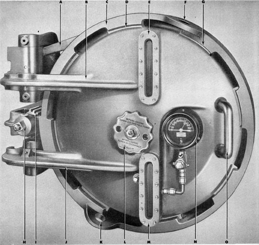
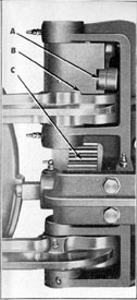
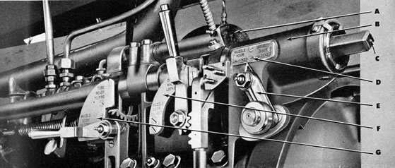
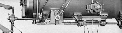
Tripping latch arm, operated by cam engaged by key in upper arm of breech door.
B
Hinge arm.
C
Locking ring.
D
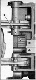
Lug on locking ring engaging lug on breech door.
E
Reflex water gage.
F
Ring for attaching pulley for loading torpedo.
G
Lug on locking ring engaging lug on breech door.
H
Squared extension on pinion gear for attaching operating handle.
I
Pinion gear which engages gear segment on locking ring.
J
Hinge arm.
K
Ring for attaching pulley for loading torpedo.
L
Adjusting hand wheel for torpedo tail stop.
M
Reflex water gage.
N
Pressure gage.
O
Hand grip.
24
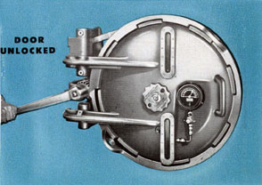
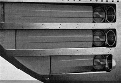
The breech door is at the inboard or loading end of
the torpedo tube. It is a bronze casting, bowl shaped,
having eight lugs fitting corresponding lugs on the
inner surface of the locking ring. On the outer
surface (see Figure 21) are two hinge arms which
extend and are pivoted to the hinge bracket at the
side of the barrel, the free ends of the hinge arms
bearing against the bracket and limiting the outward swing of the door. Also, there is a pressure
gage; a reflex crater gage in two sections; a hand
grip for opening the door; and a hand wheel in
the center for operating the torpedo tail stop.
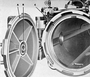
On the inner surface of the breech door (Figure
22) is an annular or ringlike groove in which is set a
rubber gasket which, when the door is closed and
locked, presses against a bead on the end of the
barrel, making the door water tight.
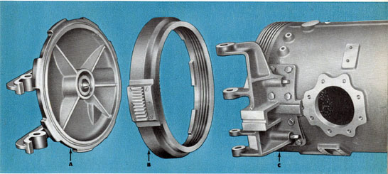
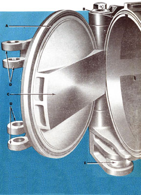
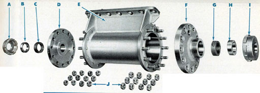
The breech door is held against the barrel by a
locking ring (see Figure 23), an annular or ring
shaped casting, having acme threads on its inner
surface which engage similar threads on the end of
Figure 22 Breech door open (A) Annular groove for rubber gasket; (B) Torpedo tail stop plate;
(C) Bead on breach face of barrel which fits against rubber gasket.
the barrel. On its inner surface are eight lugs, corresponding to the eight lugs on the outer surface of
the door. In closing the door, the lugs on the door
pass through the open spaces between the lugs on
the locking ring; the locking ring is then rotated,
bringing the eight lugs on the locking ring to bear
against the eight lugs on the door, thereby pressing
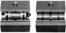
Figure 23 Breech door and locking ring disassembled
showing (A) The breech door; (B) The locking ring, with the acme
threads which engage similar threads on the end of the barrel, also
the gear segment which is engaged by the pinion gear to turn the
ring for locking and unlocking the breech door; (C) The breech
end of the barrel, showing the hinge bracket, also the acme threads
which engage the breech door locking ring.
25
the rubber gasket on the inside of the door firmly
against the bead on the end of the barrel and insuring a water-tight joint.
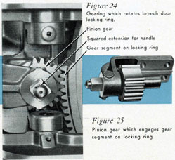
A hinge bracket, bolted to the outboard side of
the barrel at the breech end, carries the door, also
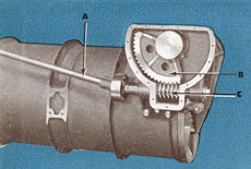
the pinion gearing (Figure 24) which rotates the
locking ring. The pinion shaft (Figure 25) has a
squared extension to which is attached the operating handle. As the handle is turned, the action of
the pinion on the gear segment attached to the side
of the locking ring causes the locking ring to rotate
(see Figures 26, 27, 28, 29).
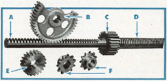
Figures 24 Figure 24 (left) - Gearing which rotates breech door locking ring. Callouts show the Pinion Gear, Squared extension for handle and Gear segment on locking ring. Figure 25 (right) Pinion gear segment on locking ring.
The locking ring carries a lug which engages an
interlocking bolt connected with the interlocking
mechanism described in a later chapter. When this
interlocking bolt is raised it clears the lug and permits rotation of the locking ring for opening the
breech door. When the bolt is lowered, it prevents
rotation of the locking ring.
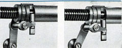
Mounted in the upper arm of the breech door is
a key (see Figure 30) which causes the tripping
latch cam to rotate when the door is being opened
or closed. This cam actuates a lever connected with
the operating shaft which leads to the tripping latch.
The tripping latch, as explained in a later chapter,
trips the starting lever on the torpedo as it is leaving
the barrel. Opening the breech door raises the trip
ping latch to permit loading a torpedo into the tube
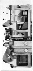
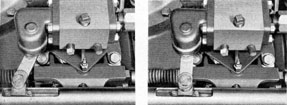
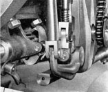
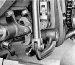
Figure 26 Door closed - left Figure 27 One-half open - right (A) Tripping latch cam; (B) Key which is engaged by upper arm
of breech door to rotate tripping latch cam; (C) Pinion and gear segment; (D) Gear segment on locking ring, pinion gear (shown in
Figure 25) removed, door in open position.
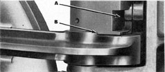
Figure 30 (A) Tripping latch cam; (B) Key on upper arm of
breech door engaging cam.
without interference. Closing the door lowers the
latch into position to strike the starting lever of the
torpedo when it has moved about three-fourths of
an inch forward from its normal loaded position.
A reflex water gage, in two sections, is mounted
on the breech door, also a pressure gage to indicate tube pressures. The pressure gage piping
is provided with a check valve (against the gage),
the purpose of which is to retain the indication of
the maximum pressure, attained when firing, long
enough to be read. In earlier vessels, the passages
from the inside of the tube to the chambers of the
reflex gage were cored to an area of about one-half
square inch. Since this area was considered
26
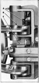
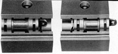
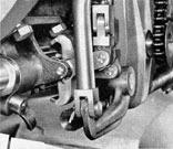
Figure 28 Door open - left Figure 29 Gear segment - right (A) Tripping latch cam; (B) Key which is engaged by upper arm
of breech door to rotate tripping latch cam; (C) Pinion and gear segment; (D) Gear segment on locking ring, pinion gear (shown in
Figure 25) removed, door in open position.
unnecessarily large, the size of these holes has been reduced to one-fourth inch diameter, by the use of
bushings, to reduce the amount of water that might
enter the submarine if a reflex gage glass were to
break.
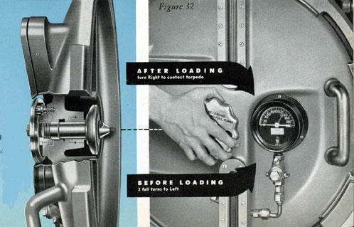
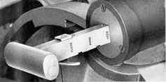
The torpedo tail Stop, fitted in the center
of the breech door (see Figure 31), holds the torpedo
against the torpedo stop bolt so it will be in proper
position to allow the spindles for the depth, speed,
and gyro setting mechanisms to drop into their
slots in the torpedo. This tail stop consists of a hand
wheel which, when turned as shown in Figure 32,
forces a non-rotating stop plate against the propeller
nut of the torpedo, holding the torpedo against
the stop bolt.
In loading a torpedo into the tube, the tail stop
is retracted by turning the tail stop handle to the
left two full turns, thereby preventing interference
with the torpedo or jamming it against the stop bolt
when closing the breech door. After the breech door
is closed, the tail stop handle is turned to the right
so the tail stop is tight against the propeller nut on
the torpedo. Then, unless the tail stop is fitted with
a rubber disc to bear against the torpedo propeller
nut, the tail stop is backed off by turning the handle
to the left about one-tenth of a turn to prevent binding the torpedo against the stop bolt.
When a torpedo tube test set is used, it is secured
by the pipe tap in the outer end of the tail stop spindle. If a rubber buffing disc is fitted on the tail stop,
its retaining stud and nuts must first be removed.
Figure 31 (left) Tail Stop in center of breech door, turned as shown in Figure 32 at right.
27
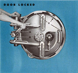
Breech Door Operation
All operating parts and mechanisms of the torpedo
tube are controlled by an interlocking system, described later in this pamphlet. Hence, opening and
closing the breech door also operates mechanisms
connected with the muzzle door operation.
To open the breech door, it must first be made certain that the muzzle door is closed, and that all water
which entered the tube during the previous firing
is drained off. With this positively assured, the
breech and muzzle door interlocking lever, located
at the side and just over the breech end of the barrel, is moved to Breech Door Unlocked position on
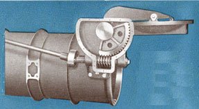
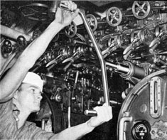
Figure 33 Turning breech door locking ring; A Operating handle turning locking ring; B Pinion gear engaging gear segment on locking ring; C Lugs on locking ring engaging lugs on breech door
the indicator. The breech door operating handle is
then attached and turned as shown in Figures 33
and 34. The handle operates the pinion engaging
the gearing and rotates the locking ring, bringing
the lugs on the locking ring in line with the open
spaces between the lugs on the door, removing the
pressure on the door so it can be swung open when
pulled by the hand grip.
A word of caution: The door must be held by
hand until it is fully open and bears against the
stops on the bracket. Jerking the door open and
allowing it to swing under its own momentum to
an abrupt stop may damage the mechanism and
prevent water tightness when the door is closed.
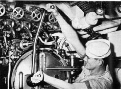
Figure 34 Breech door locking ring
turned, door unlocked, lugs on door
disengaged, door ready to open.
28
THE MUZZLE DOOR
AND ITS MECHANISM
Muzzle doors were designed for manual operation only on all torpedo tubes in: SS 198-242, 247-251,
253-274, 281 and 282, and on stern tubes in SS 243,
246 and 252. The text which follows, down to the
heading "Power Operation" on page 32, describes
this manually operated mechanism. The balance of
this chapter deals with the mechanisms designed
primarily for power operation, with manual operation retained only for emergency use, which are
installed on all other torpedo tubes in submarines
subsequent to SS198.
The Muzzle Door Mechanism consists of the door
itself (Figure 35); a bracket; a door arm; a worm
and worm segment (Figures 36 and 37); a breech
bracket, located over the breech end of the tube;
an operating shaft (see Figures 42, 43, 44); a muzzle
door indicator (see Figure 44), and interlocking features which are described in Chapter 4.
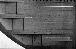
The muzzle door, like the breech door, is a bowl
shaped bronze casting. In a groove around the
inner surface of the door is set a rubber gasket, the
same as on the breech door, which, when the muzzle door is closed and locked, is pressed against a
V-shaped beading around the end of the barrel
(Figure 35), forming a water tight seal.
Figure 36 Gearing for opening and closing manually operated muzzle door, barrel rolled on side to show gearing. (A) Operating shaft; (B) Worm segment; (C) Worm which operates worm segment to open or close door.
Figure 35 Muzzle door, open at 45 degrees. (A) Annular groove containing rubber gaskets; (B) V-shaped beading around end of barrel; (C) Rubbing strip; (D) Connections for shutter door arms; (E) Operating shaft connection (this being for power operated muzzle door).
Figure 37 Showing worm and worm segment in muzzle door open position.
29
Manual Operation
Muzzle doors and their operating mechanisms for
stern tubes are similar in general design and operation to those for bow tubes. Differences arise, principally, from the omission of shutters in some
vessels. Where this is done, it sometimes has been
possible to obtain operating advantages by hinging
the doors on other than vertical axes. Reference
must be made to the plans or drawings known to
be applicable to a particular vessel or class of vessels.
Every submarine carries a set of the drawings or
blueprints which apply specifically to it.
The muzzle door and shutter are opened and
closed by means of the operating shaft, which extends from the muzzle door to the breech bracket
at the breech end of the tube, this shaft being fitted
with appropriate stuffing boxes, couplings, and universal joints as necessary.
All operating mechanism and controls for the
muzzle door are located at the breech end of the
tube and, as stated in previous references to the
breech door, both the breech door and the muzzle
door are linked together by the interlocking mechanism so that one can not be opened until the other
is closed and locked.
The muzzle doors of bow tubes open out into
chambers at either side of the submarine, and these
chambers are equipped with shutters (see Figures
40 and 41 for the type installed in submarines under
construction as this pamphlet is issued) which are
opened and closed as the muzzle door is opened
Figure 40 Outboard view showing muzzle door with shutters open.
Figure 38 Opening muzzle door by hand (action to left).
Figure 39 Closing muzzle door by hand (action to right).
and closed, a shutter arm being connected to the
door arm on the muzzle door (see D in Figure
35). The closing of the shutters when the torpedo
tube is not in action eliminates the resistance that
would be created by water entering the chambers
Figure 41 Outboard view showing shutters for muzzle doors closed.
30
were the shutters left open, so that the speed of the
submarine is not affected.
The forward ends of the shutters shown by Figures
40 and 41 are fitted with vertical pins upon which
rollers are mounted. Grooves for these rollers are
provided in the horizontal plating above and below
each shutter, so that as the rear of the shutter is
thrown in or out by the shutter arm of the door
mechanism (to open or close the shutter as the
muzzle door is opened or closed) the forward end
of the shutter slides to the front or rear, sliding
behind the hull plating forward as the shutter is
opened.
In certain submarines other types of shutters will
be found. For instance:
(1) A type similar in all respects to that pictured
by Figures 40 and 41 except for being curved around
a horizontal axis, and
(2) A type which is hinged at the front end instead of having the front end slide on rollers. On
this type, the pin at the end of the shutter arm
engages a slot in the shutter-frame instead of a hole.
Due to the lost motion which develops with this
type of linkage, such shutters have a special locking
mechanism to hold them open, so that they will
not foul a torpedo.
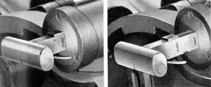
Figures 42 and 43 Cylinder slide on muzzle door operating shaft, showing (left) interlock bolt engaged in breech door unlocked position, (right) muzzle door unlocked position.
The interlocking mechanism which controls the
opening and closing of both the breech and the
muzzle doors is fully described in the following
chapter of this pamphlet. Briefly, however, the operation of this mechanism as it applies to the muzzle
door is as follows:
Located on the breech bracket at the breech end
of the tube is a system of levers and indicators, as
shown in Figure 44. As the breech and muzzle door
interlock lever is moved from one position to the
other, it engages or disengages bolts in the cylinder slide which moves in the breech bracket (see
Figures 42 and 43), thereby locking or releasing the
muzzle door operating shaft. To open the muzzle
door, the breech and muzzle door interlocking lever
is moved to the "Muzzle Door Unlocked" position
on the indicator plate. This can not be done, however, until the breech door has been closed and
Figure 44 Breech bracket and interlocking levers which control opening and closing of the breach and muzzle doors.
(A) Indicator
showing movement of muzzle door as it opens and closes; (B) Breech bracket for cylinder slide connected with muzzle door operating shaft; (C) End of muzzle door operating shaft to which
handle is attached for opening and closing muzzle door; (D) and
(E) Breech and muzzle door interlock indicator and lever; (F)
Drain valve and muzzle door interlock lever and indicator; (G)
Muzzle door unlocked and tube ready to fire interlock lever and
indicator.
31
locked, as a lug on the breech door locking ring
engages a bolt which prevents moving the lever
until it is in the right position. The drain valve and
muzzle door interlock lever is then placed on the
"Drain Valve Locked" position of the indicator
plate. The firing interlock lever is placed at "Muzzle
Door Unlocked" position on its indicator plate. The
muzzle door operating handle is then attached to the
squared extension on the end of the muzzle door
operating shaft and turned counter-clockwise (to
the left), as shown in Figure 38.
This counter-clockwise turning of the muzzle
door operating handle operates the worm and worm
wheel in the muzzle door bracket and opens the
door ready for the operation of the firing mechanism. As the muzzle door opens, its movement is
shown on the muzzle door indicator, which is
shown at (A) in Figure 44.
To close the muzzle door, the sequence of operation is reversed. The firing interlock lever is moved
to the "Muzzle Door Unlocked" position, opening
the interlock switch and unlocking the door. The
muzzle door operating handle may now be rotated
in a clockwise direction (to the right) as shown in
Figure 39, closing the door. When the muzzle door
indicator pointer is at 0 degrees the door is closed,
and the breech door locking bolt may be thrown,
unlocking the locking ring on the breech door.
Power Operation
The power operating mechanism for muzzle doors
is shown in Figure 45 (refer also to Plate One, on
which the bottom view shows the same tube more
completely). The muzzle door operating shaft is
operated by a hydraulic power cylinder, and is
located below and to the inboard side of the tube.
The power cylinder is connected by tubing with
the control valve, located just over the torpedo tube
and connected with the vessel's hydraulic manifold.
The control valve is operated by means of a thrust
rod which moves through the interlock sleeve connected with the cylinder slide in the breech bracket.
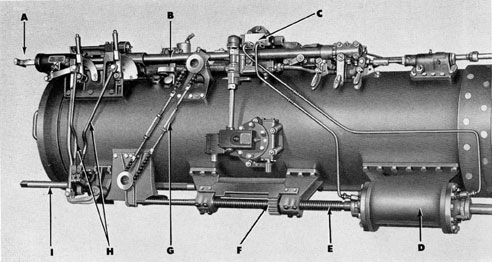
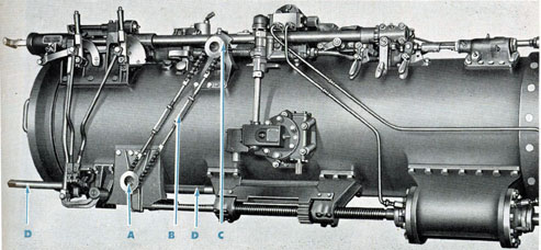
Figure 45 Breech end of tube, showing parts for power operation of muzzle door.
(A) Hand grip attached to thrust rod for operating control valve; (B) Interlock sleeve, through which thrust rod
operates; (C) Control valve; (D) Power cylinder; (E) Muzzle door
operating shaft; (F) Jacknut gear which connects with spur gear on
shaft for operating by hand; (G) Interlock chain; (H) Connecting
rods from interlock levers to lock or release muzzle door operating
shaft; (I) Shaft for operating by hand.
32
Figure 46 Control valve operating handle for power operation of muzzle door handle in door open position.
Figure 47 Handle in muzzle door closed position -left. Figure 48 Handle set for opening door by hand - right.
The control valve handle (Figure 46) which operates the thrust rod has recesses on the under side
which lock it in position, being released by a trigger,
so the handle is locked when set for muzzle door
open (Figure 46), muzzle door closed (Figure 47),
or for hand operation (Figure 48). The thrust rod
parts are shown in Figures 49, 50, 51.
The cylinder slide has slots which engage the
interlock bolts for the breech and muzzle door and
drain valve and muzzle door interlocks, the same
as with manual operation, so the thrust rod cannot
be operated unless these interlock bolts are in correct position.
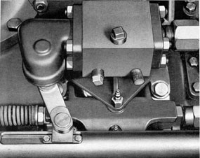
The muzzleward end of the thrust rod is connected to the control valve by an arm (Figure 52).
When the control valve handle is in closed position,
the arm is toward the muzzle door (Figure 52);
when in open position, the arm is toward the breech
door (Figure 53); when in neutral for hand operation, the arm is in the center (Figure 54).
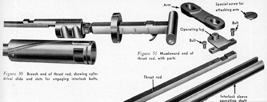
Figure 49 Control valve operating handle disassembled.
(A) Thrust rod and handle; (B) Slot for interlock bolt; (C) Cylinder
slide which moves in breech bracket; (D) Teeth on interlock sleeve
operating shaft engaged by gear on interlock chain to move
operating shaft and cylinder slide to show opening and closing of muzzle door on indicator.
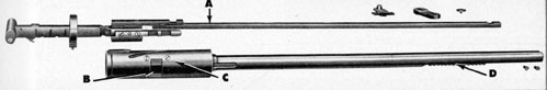
Figure 50 Breech end of thrust rod, showing cylindrical slide and slots for engaging interlock bolts.
Figure 51 Muzzleward end of thrust rod, with parts.
33
Figure 52 Control valve for operating muzzle door by power,
showing arm connected to thrust rod in muzzle door closed position.
Position for muzzle door open shown in Figure 53, below.
Figure 54 shows the control valve in neutral position for opening
and closing the muzzle door by hand.
Figure 53 left - Figure 54 right
Figure 55 left - Figure 56 right Figure 55 Control valve opened to show interior (view taken
from back of valve as shown in Figures 52, 53, and 54), with piston
in position for muzzle door closed. Position for muzzle door open
shown in Figure 56; neutral position for operating by hand in
Figure 57; interior with piston removed in Figure 58.
Figure 57 left - Figure 58 right
Cut-away views of the valve are shown, Figure 55
being with the piston in muzzle door closed position
(hydraulic pressure being on the muzzleward end
of the operating cylinder); Figure 56, muzzle door
open (hydraulic pressure being on the breechward
end of the operating cylinder); Figure 57, neutral
for hand operation (hydraulic pressure being
blanked off from both ends of the operating
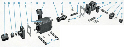
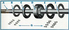
Figure 59 The control valve parts disassembled.
(A) Connector
nut; (B) Tailpiece; (C) Gasket; (D) Flange; (E) Gasket; (F)
Valve body; (G) Connection to supply from manifold; (H) Connector nut; (I) Piston; (J) Pin; (K) Pin; (L) Link; (M) Gasket;
(N) Bracket; (O) Arm; (P) Shaft; (Q) Stuffing box; (R) Follower
ring; (S) Gland; (T) Nuts and pins for attaching flange and
bracket to valve body; (U) Washers and cotter pins for piston and
link; (V) Bolts for bracket.
cylinder, which are cross-connected through a passage
in the valve piston so that oil may pass freely from
one end of the operating cylinder to the other while
Figure 61 Operating rod and packing for power cylinder.
(A) Shaft; (B) Retaining ring; (C) Piston cup (leather); (D) Piston;
(E) Piston cup (leather), (F) Retaining ring; (G) Machine screws
for fastening retaining rings to piston.
the muzzle door is being opened or closed by hand);
Figure 58 with piston removed. Figure 59 shows the
parts of the valve disassembled.
Figure 62 Breech end of muzzle door operating shaft.
(A) Threads on shaft which engage gear (B) for operating interlock
chain; (C) lack nut gear engaged by long spur gear on hand
operating shaft; (D) Threads on operating shaft engaged by jack
nut gear; (E) Gear; (F) Sprockets.
Figure 63 Showing the interlock chain in muzzle door open, tube ready to fire position.
(A) Connection with operating shaft; (B) Interlock chain; (C) Gearing connecting with interlock sleeve
operating shaft; (D) Shaft for hand operation.
35
Figure 64 Opening power operated muzzle door by hand.
(A) Handle attached for hand operation; (B) Jack nut gear engaged
long spur gear under; (C) Gear indicator and guard; (D) projections on guard with which jack nut gear must be lined up when changing
from hand to power operation.
The hydraulic power cylinder (see Figure 45) is
operated by oil under pressure from the vessel's
hydraulic manifold leading through the control
valve. Views of the power cylinder disassembled
are shown in Figures 60 and 61.
As the operating shaft is moved by the power
cylinder, teeth on the breech end of the shaft engage
gearing (Figure 62) operating the interlock chain,
which is connected at the top with gearing engaging
teeth on the under side of the interlock sleeve operating shaft. As the muzzle door opens or closes, the
interlock sleeve operating shaft and the cylinder
slide move, rotating the pointer on the muzzle door
indicator.
Provision also is made for opening and closing
the power operated muzzle door by hand should
it become necessary. A hand operating shaft is provided (Figures 63 and 64). At the end of this shaft
is a long spur gear which engages a jack nut on the
muzzle door operating shaft (Figure 64), the jack
nut having teeth parallel with the shaft on its outer
surface and a screw thread on its inner surface to
engage the thread on the power shaft. When the
muzzle door is opened or closed by power, this jack nut, being kept from rotating by its engagement
with the long gear on the hand operating shaft
rides along with the door operating shaft between
the two extensions of the bracket, without touching
either (since such contact would prevent the full
movement of the door). When rotated by the long
gear on the hand shaft, the jack nut first moves
along the threads of the operating shaft (since this
takes less force than to move the door) until it
comes against one of the two extensions of the
bracket, and then, since it can move no further
along the operating shaft, moves the shaft, thus
operating the door.
The hand operating shaft is acted upon by
special interlocking mechanism so as to obtain the
same results as in power operation. This mechanism
consists of rods extending down from the interlock
levers (Figure 45) to, dogs which appropriately engage or release a gear on the hand operating shaft
(in Figures 65, 66 and 67).
For further information, consult section 24 of
Chapter 12.
Figure 65 Hand shaft interlock, in position when muzzle door is locked closed.
Figure 66 Hand shaft interlock, position for muzzle door open, tube ready to fire.
Figure 67 Hand shaft interlock, position for opening muzzle door by hand.