All U. S. Navy torpedoes have the starting lever,
the side setting gyro setting sockets, the-depth setting sockets, and the speed setting sockets (when
fitted) in the same locations relative to the center
line of the torpedo and to its tail. Torpedoes are
divided into three groups according to the location
of the guide stud, the distances from the tail to the
front of the guide stud being 109.0 inches, 141.44
inches, or 150.44 inches, depending upon the length
of the torpedo.
The torpedo tubes described in this pamphlet
were designed primarily for the Mark 14 torpedo,
which has the front of the guide stud 141.44 inches
from the end of the tail, hence they will accommodate such torpedoes without any adjustment or
alteration of either the tube or the torpedo. The
length of this torpedo has been increased to 246.0
inches, but this increase in length does not in any
way affect the operation of the torpedo tube.
These tubes were designed also to accommodate
the Mark 10 Modification 3 torpedoes, which have
the front of the guide stud 109.0 inches from the
tail, by changing the stop bolt to the rear housing,
described in Chapter S, page 109 of this pamphlet.
With this torpedo, however, as with all others except the Mark 14 and Modifications, it is necessary
to use the gyro setting socket adapter described in
Chapter 7, in the section on the Gyro setting mechanism, and specifically on page 90. This adapter is
required if gyro angles are to be set while this torpedo is loaded in the tube.
Mark 10 Modification 3 torpedoes are originally
issued with a guide stud which is Tee shaped in
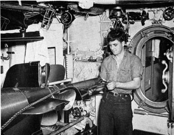
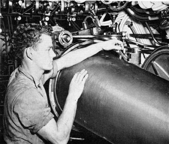
Figure 222 Loading the torpedo first step. A tail piece having
one end shaped to fit into the
propeller shaft, and with a pulley
at the other end, is inserted in
the propeller shaft, and the cable
is led around the end of the pulley. Illustrations on the following
pages show the succeeding steps.
124
cross section, and which is too high to suit the
guide slot in torpedo tubes such as those described
in this pamphlet. The flat, low guide stud used on
the Mark 14 torpedoes is to be used. This guide
stud has holes for four bolts, whereas the Mark 10
Modification 3 torpedo air flask is tapped for only
three bolts. Therefore, when attaching the guide
stud on the torpedo, the vacant hole in the guide
stud should be placed toward the tail of the torpedo.
The foregoing also applies to torpedoes Mark 9
and Modifications. In addition, on older Modifications of Mark 9 torpedoes, the depth index runs to
only 25 feet instead of to 50 feet as on modern torpedoes, and the scale index is 51 degrees of dial to
five feet of depth instead of 20 degrees to five feet,
so that the scale on the depth setting mechanism on
the tube may not be read directly when these torpedoes are
being used (although, from the foregoing
information, an equivalent scale may be readily
prepared).
In Chapter 2, describing the barrel, reference is
made, briefly, to the overall lengths and the effective lengths of bow and stern tubes, the effective
length referring to the length of torpedoes that
can be accommodated in the tubes. Experience on
any submarine will soon make it possible to determine at a glance whether any given torpedo of a
known length can be fitted into either the bow or
the stern tubes of the particular vessel. There are
certain torpedoes, principally the Marks 11, 12, and
15 torpedoes, of the original length of 271.0 inches,
which can be fired from the stern tubes of some
submarines. These torpedoes, however, have the
front of the standard guide stud 150.44 inches from
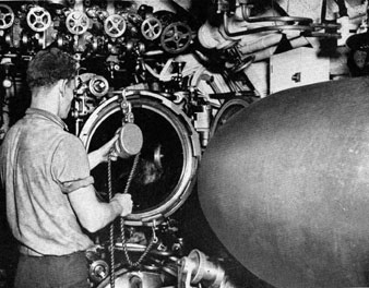
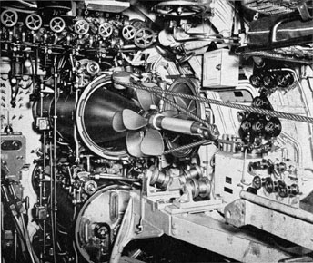
Figure 223 Loading the torpedo, second step. The block and
tackle is attached to the two
eyes on the breech door locking
ring.
125
the tail, therefore a special guide stud (see O.P. 586)
must be used for these- torpedoes, and the lower end
of the stop bolt must be shaped to fit the special
guide stud. The stop bolts now issued are so shaped,
these being shown in all applicable illustrations in
this pamphlet.
2. TORPEDOES (BRITISH)
Certain British torpedoes are of suitable length for
firing from the tubes described in this pamphlet
by using the special guide stud, although none of
the operating or setting mechanisms on the tube
will line up properly with the torpedo. The "air
lever," which corresponds with the starting lever
on USN torpedoes, is farther forward, and is to
port of the torpedo center line instead of to starboard. Furthermore, as the air lever swings to the
rear to start the torpedo, its tip rises above the
21.125 inches inside diameter of the tube. Hence,
should it be found necessary to attempt to use these
British torpedoes, it will be necessary to improvise
means, such as a lanyard, for starting the torpedo,
also to cut off the tip of the air lever so that it will
not dig into the wall of the tube when the lanyard
is pulled.
3. FIRING PROCEDURE,
LIVE TORPEDO
The following are the steps necessary in firing a
torpedo, though it is not necessary that they be
executed in the exact sequence given here:
(a) Ready the torpedo: Set the speed setting
socket in the torpedo to "Intermediate" on three
speed torpedoes, or to "Low" on two-speed torpedoes; that is, with the flat side of the socket parallel
to the center line of the torpedo. The mechanism on
the tube must also be set to "Low." Set the depth
setting socket on the torpedo, also on the tube
mechanism, to "10 feet." Set the torpedo gyro to "0,"
the corresponding setting for the tube mechanism
being "0" for a bow tube and "180" for a stern tube.
(b) Prime the firing valve in accordance with the
following steps, there being no charge in the impulse tank, or the impulse stop valve, if fitted, being
closed:
(1) Open the filling valve on the firing valve
head, also the drain valve on the firing valve body.
(2) Fill with clean, fresh water through the filling funnel until the water flows, not merely drips,
from the drain valve.
(3) After the water stops flowing from the drain
valve, close both valves.
(4) Exercise the firing valve by hand, or by firing
air charges inboard, as described later in this chapter.
(5) Repeat steps 1, 2, and 3.
Note-Opening either the filling valve or the
drain valve on the firing valve after the impulse
pressure is on the firing valve may fire the tube.
The hand wheels originally fitted on these valves
are now being replaced by small square knobs so
that a wrench or a pair of pliers will be required
for opening or closing the valves. Also, there is no
positive way of knowing exactly how many shots
one "priming" is good for. Very little, if any, of
the priming water should be lost, either by firing
or by evaporation. However, the possible excessive
tube pressures due to firing with too little water
in the throttling chamber are considered sufficient
to warrant the extra trouble of filling the throttling
chamber frequently, especially so when firing is
anticipated.
The firing valve may be exercised by hand by
removing the filling valve and inserting the firing
valve lifter in the tapped hole in the head of the
bolt which secures the orifice disc to the firing valve
cup, as described in Chapter 5, see page 56.
(c) Inspect the bore, with the breech door open,
and using a flashlight or a portable lamp, to make
certain there is no foreign object in the tube, also
that the stop bolt is down, the tripping latch is up,
and that the spindles of the depth setting, the speed
setting, and the gyro setting mechanisms are in the
out or retracted position.
(d) Open the vents inboard.
(e) Load the torpedo, easing it forward, gently,
against the torpedo stop bolt in order to avoid dam
age which might prevent the stop bolt from with
drawing properly when the tube is fired, or which
might cause it to lift prematurely.
As the torpedo is being loaded into the tube, make
126
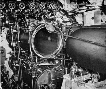
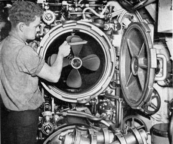
Figure 224 Loading the torpedo, third step. With the block
and tackle attached, the torpedo
is eased along the runways until
it enters the tube, making certain that the guide stud on top
of the torpedo enters the guide
slot in the top of the barrel.
certain that its stop valve is open, that the starting
gear is set to run, and that the starting lever safety
stick, lock or wedge has been removed.
When loading Mark 11, 12, or 15 torpedoes or
Modifications, which require the special guide stud
previously referred to in this chapter, it is necessary to engage the stop bolt in the slot near the end
of the guide stud instead of against its front face.
To do this, load normally until the front face of the
guide stud is against the stop bolt. Then raise the
stop bolt by "firing" as when firing an air charge
inboard, but without pressure in the impulse tank,
or with the impulse stop valve closed. Hold the
firing key closed, or the firing lever down, and load
the torpedo in a few inches further, but not more
than 8 1/2 inches. Release the firing key or lever and
ease the torpedo home.
With the Mark 11, 12, or 15 torpedoes or Modifications, it is even more important to engage the
stop gently, and without a jar, than with other torpedoes, since the special guide stud is necessarily
weaker than the standard guide stud. Make certain
that the interlocking mechanism is properly re-engaged, the same as after firing an air charge inboard.
(f) Remove the propeller lock.
(g) Charge Impulse Tank-The impulse stop
valves at the firing valves may be either open or
closed while charging the impulse tank. In either
case, the tightness of the firing valve should be observed during the charging operation if practicable.
This may be done quite readily if the breech doors
are open. A small leak of air through the firing valve
will reduce the impulse tank pressure, possibly to a
dangerous degree. Also, if the muzzle doors are
open, it will cause a bubble trail, or, if the muzzle
doors are closed, it may build up a sufficient pressure in the tube to crack open the muzzle door, in
which case whatever tube pressure exists in the after
portion of the tube will act to force the torpedo
against the stop bolt, which is not designed to
effectively resist such pressure.
The firing valve is supposed to be held closed by
the impulse tank pressure in the chamber above the
valve until the instant of firing. The air which enters
this chamber to build up and maintain the pressure
does so by "leaking" past the outer cylindrical wall
of the valve through small grooves in the piston
rings on the valve. These openings must be very
127
small in order that sufficient air will not pass through
them to impede the opening of the valve by preventing the sudden drop of pressure in the chamber
above the valve which should be caused by venting
it when firing. On the other hand, if these openings
are clogged, as by heavy grease, corrosion products,
or other foreign matter, the valve will fly open if
pressure is put on it too rapidly, as by suddenly
opening the stop valve to admit full impulse pressure, or, conceivably in extreme cases, by too sudden a rise of impulse tank pressure while charging
with the impulse stop valve open. After charging
the impulse tank, close the charging valve. Do not
let the tank "ride" upon the line.
(h) With tail stop retracted, close the breech
door, and take up tightly on the tail stop, to make
certain that the forward face of the torpedo guide
stud is against the stop bolt. Then, if the tail stop
plate is not fitted with a rubber disc to bear against
the torpedo propeller nut, back off the tail stop
about one-tenth of a turn to prevent binding the
stop bolt.
(i) Enter setting spindles, the gyro, depth, and
speed, first ascertaining that all readings on the
setting dials correspond with the known settings on
the torpedo. It is considered that the most practical
way of insuring that the settings correspond is to
make a practice of maintaining both the tube units
and the sockets in the torpedoes set as follows, except
when torpedoes are loaded and initial settings have
been made:
Gyro-Set at 0 degrees. If spread setting mechanisms are fitted, set these at 0 degrees also.
Depth-Set at 10 feet.
Speed-Set tube units to "low." The sockets in
the torpedoes have previously been set to "low" in
two-speed torpedoes, and to "Intermediate" in three
speed torpedoes, in accordance with the instructions
given in step (a) of this section.
(j) Poppet Valves-Check the, poppet valves to
make certain that the gag nuts are backed off, and
that manually operated stop valves in the poppet
valve drain lines are open.
(k) Flood Tube, when ordered.
(l) Set gyro, depth, and speed, when ordered,
and withdraw the depth and speed setting spindles.
(m) Open the muzzle door, when ordered, making certain that the operating shaft is turned through
its full movement, until stopped.
(n) Throw interlocking lever to "Tube Ready to
Fire" position, and report tube ready to fire.
(o) When firing, be sure to hold the electrical
firing key closed, or the firing lever in the "firing"
position if firing manually, for at least two seconds,
preferably four. Otherwise, the firing valve may
close before the torpedo receives a full impulse.
(p) Close the muzzle door.
(q) Close poppet valve (as described in Chapter
6, on page 71) after the tube has vented the impulse
air through the poppet valve, but before an excessively large quantity of water has entered. If the poppet valve discharges into a bilge or an open tank
which already contains water, some of this water
will be blown up into the torpedo room, giving the
impression that water is entering through the poppet
valve before such is actually the case. According to
the best information available, an interval of at least
five seconds is to be expected between firing and any
large rush of water through the poppet valve.
(r) Close muzzle door.
(s) "Blow down" the tube, when ordered. Immediately after a war shot in the vicinity of enemy
surface vessels, this may not be desirable. When all
water is out of the tube, close the drains and vent
the blowing air from the tube.
(t) Do not attempt to open the breech door until
all water is out of the tube, and the pressure in the
tube has equalized with that in the ship.
4. FIRING PROCEDURE, MINES
Reference to the Ordnance Pamphlet covering the
specific mine issued for use is necessary in order to
secure the correct instructions regarding the operation of torpedo tubes when they are being used to
launch mines.
5. FIRING PROCEDURE, DUMMY
TORPEDOES
It is intended that dummy torpedoes be fired,
generally speaking, for one of two purposes: (a)
128
For training personnel; (b) to test the operation of
a tube, or the shutter clearances, or other features
connected with the operation of the tube. In either
case, the dummy torpedo is used for the purpose of
simulating as nearly as practicable the firing of an
actual torpedo without hazarding the loss of a valuable mechanism. It is suggested, therefore, that the
routine of firing be carried out, or simulated, so far
as circumstances permit, when firing dummy torpedoes as well as when firing live torpedoes. An
exception would be the firing of dummy torpedoes
with the poppet valves inoperative for the purpose
of progressively acquainting new personnel with the
operation of torpedo tubes.
From a digest of the Bureau's records, it appears
that, with a given impulse pressure, and at a given
depth, the maximum tube pressure may be expected
to be from four to six pounds per square inch
lower, and the ejection velocity possibly three feet
per second higher, with a dummy torpedo than
with a live torpedo. Such effects might be expected
from the fact that a dummy torpedo, being proportioned to float, is several hundred pounds lighter
than the live torpedo which it simulates.
6. FIRING PROCEDURE, WATER SLUGS
Generally speaking, water slugs are fired for the
purpose of (a) training personnel; (b) exercising
tube mechanisms; (c) establishing or checking firing valve clearances. If the last, the results are not to
be regarded as conclusive, but only as indicative of
what may be expected from actual firings. In this
connection, it is understood to be the practice of one
builder of submarine torpedo tubes to establish firing valve clearances such that, when on the surface,
a maximum tube pressure of 59 to 65 pounds per
square inch will be attained when firing water slugs
with an impulse tank pressure of 400 pounds per
square inch. It appears to be the result of this builder's experience that, when such pressures are attained, the desired pressures and velocities are apt to
follow at all depths when firing torpedoes with the
prescribed impulse tank pressures. See, however,
Section 9 of this same chapter.
Do not have the poppet valve "on" when firing
water slugs. This is important, since without a torpedo, mine, or dummy in the tube it will open
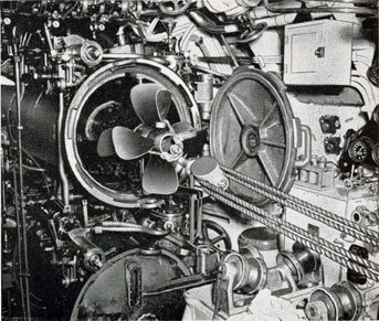
Figure 225 Loading the torpedo, fourth step. When the torpedo is part way in the barrel,
the safety guard is removed
from the starting lever, and the
index dials on the depth, gyro,
and speed mechanisms in the torpedo are checked to make certain they are properly set, also
that the torpedo stop valve is
open, and that the starting gear
is set to run.
129
immediately when the service line pressure is applied to the operating cylinder. The safest procedure
is to gag the poppet valves when firing water slugs.
Arrangements have been devised from time to time
to permit the poppet valve to function in connection
with the firing of a water slug, but since the operation does not exactly duplicate, in timing, the results obtained when firing a dummy or a live
torpedo, and since the use of such arrangements is
attended by the hazard of lodging some foreign
material in the way of the muzzle door, or in the
poppet valve, the use of such arrangements is not
recommended.
7. FIRING PROCEDURE, AIR
CHARGE, INBOARD
Air charges, in general, are fired inboard for the
purpose of (a) instructing personnel, or (b) exercising certain operating mechanisms of the tube,
such as the firing mechanism, stop mechanism, and
the gyro setting spindle retracting mechanism. The
procedure for firing an air charge inboard is as
follows:
(a) Open the breech door. The breech door is to
remain open until the interlocking mechanism has
been reconnected and locked.
(b) Withdraw depth and speed setting spindles.
(c) If a torpedo is in the tube, and it is desired to
make certain that it does not slide forward past the
stop bolt while that bolt is raised at the firing of the
air charge, withdraw the gyro setting spindle, pull
the torpedo back a few inches and lash it there. This
will also prevent the breech door from being closed
during the exercise.
Note-This precaution of pulling the torpedo
back and lashing it in place is important. On at
least one occasion a torpedo has slid forward past
the stop bolt while a tube was being exercised, and
the muzzle door was damaged to such an extent
that it could not be remedied without dry docking.
(d) Unlock and remove the padlock from the
firing interlock signal arm (the interlock warning
"flag"), and raise that arm to the vertical position.
This disengages the firing interlock bolt from the
clutch shaft (as shown in Figure 85 on page 46),
and permits the stop and firing mechanisms to function regardless of the position of the breech door or
the drain valve interlock lever, as explained in
Chapter 4 (see page 46).
(e) Open the firing impulse stop valve, if one is
installed on the tube.
(f) Charge the impulse tank to not over 100
pounds.
(g) Throw the firing interlock lever to "Tube
Ready to Fire," and report tube ready to fire air
charge inboard.
(h) When ordered, "fire" the tube.
(i) Throw the firing interlock lever to "Muzzle
Door Unlocked" position, lower the firing interlock
signal arm, engaging the interlock bolt with the
clutch shaft, then engage and lock the padlock.
(j) Place the tube in original condition, or in
other condition, as ordered.
8. NOTES PERTAINING TO
MARK 15 TORPEDOES
The following notes concern the handling of Mark
15 or Modifications torpedoes in the after torpedo
rooms of vessels in which the after tubes are long
enough to take these torpedoes. They also apply to
other torpedoes of comparable length (22 feet 7
inches), such as Marks 11 and 12. These notes are
taken from service experience, hence they should be
carefully observed.
To load these torpedoes into the torpedo room,
first remove the wooden loading chock, or skid, just
inside the loading hatch, to give room for lowering
the tail. The cradle, instead of being secured and
pivoted at its lower end on the deck, is entirely
suspended by chain falls. The same chain hoists
may be used as when handling the cradle normally; that is, two forward, at the sides, and one in
the center, aft.
Lower the torpedo in the normal manner until
its nose joint about touches the deck. Then lower
the tail, raising the nose end of the cradle slightly
if necessary, to allow the torpedo to be slid down a
little more in order that the tail will clear. As the
nose of the torpedo slides between the sling lines to
130
the after, or lower, chain hoists, those lines may be
chafed severely. This can be remedied by the use of
a strong-back or yoke having the chain hoist hook
applied at the center, and short lifting lines running
from the ends to the sides of the cradle.
9. IMPULSE PRESSURES AMP
FIRING VALVE SETTING
It was originally intended that a single impulse
tank pressure of 400 p.s.i. should be used with this
type of tube at all depths from surface down to 120
feet to keel, with any type of torpedo, and in both
bow and stern tubes. The firing valve was adjusted
so that, at 120 feet to keel, a torpedo launching
velocity of 30 to 40 feet per second was attained
with a maximum tube pressure of 60 to 70 p.s.i.
more than the "static head" (depth, in feet, from
surface to the centerline of the tube, multiplied by
0.44, giving p.s.i.). This setting was obtained by
calibration firings of water slugs while on the
surface, the valve clearance being established to give
a maximum tube pressure of about 60 p.s.i. The
higher launching velocities attained at lesser depths
were accepted in order to obtain the advantage of a
uniform impulse tank pressure.
Subsequent to the adoption of poppet valves, and
principally to favor their successful operation, the
variation of impulse tank pressures with depth was
authorized. From surface down to periscope depth,
the authorized impulse tank pressure became 300
p.s.i., from periscope depth to 120 feet to keel 400,
and from 120 to 180 feet to keel 525 p.s.i. The valve
clearance was established as before. No variation of
impulse tank pressure was authorized for different
torpedoes, for different ship speeds, or between bow
and stern tubes.
Extensive experimental firings have recently been
completed. These firings were conducted with the
idea of determining impulse tank pressures which
would:
(1) Eliminate the launching bubble to the greatest practicable degree.
(2) Favor the run of the torpedo to the greatest
possible extent, that is, launch it in such a way that
it would have the minimum tendency either to
broach or to take an initial dive. The following data
and conclusions proceed from these firings:
Figure 226 Loading the torpedo, fifth step. The torpedo is
eased further into the tube, riding on the tube rollers, the block
and tackle is detached, then the
torpedo is eased gently info
place against the stop bolt, care
being taken to avoid damaging
the stop bolt by forcing the Torpedo against it.
131
FOR TORPEDOES MARK 23
Keel Depth (Feet)
Ship's Speed (Knots)
Tubes
Best Impulse Tank p.s.i.
Surface
5-18
Bow
250
Surface
5-18
Stern
400
40-90
2-3
All
350
90-120
2-3
All
400
120-160
2-3
All
500
160-200
2-3
All
600
FOR TORPEDOES MARK 18
Keel Depth (Feet)
Ship's Speed (Knots)
Tubes
Best Impulse Tank p.s.i.
Surface
5-12*
Bow
150
Surface
5-18
Stern
350
40-65
2-3
All
250
65-90
2-3
All
350
90-120
2-3
All
400
120-160
2-3
All
500
160-200
2-3
All
600
*Above 12 knots Mark 18 torpedoes may be expected to broach and
run erratic when fired from bow tubes.
Since the originally intended maximum impulse
tank pressure was 400 p.s.i., higher pressures than
this should not be used unless the impulse tanks,
piping and firing valve bodies are known to have
been successfully subjected to hydrostatic test in
accordance with the requirements of the Bureau of
Ships (150 per cent of working pressure).
For best performance with the pressures set forth
above, the firing valve clearance should be established to give a maximum tube pressure of about
60 p.s.i. when a water slug is fired on the surface,
with an impulse tank pressure of 300 p.s.i.
No torpedoes other than Marks 18 and 23 were
fired during these tests. If other torpedoes must be
fired before more complete information is published,
proceed in accordance with relative speeds. For
example, a torpedo Mark 14 or Modification should,
if set for high speed, be fired with the impulse tank
pressure established for the torpedo Mark 23. If set
for low speed, the impulse tank pressure for a
mark 18 should be used.
Poppet valves should be used at all depths.
Poppet valves should be timed, with a stop watch,
as follows, in order to eliminate the bubble effectively:
Keel depth
Valve open
30-90 ft.
5 sec.
90-120 ft.
3 1/2 to 4 sec.
120-209 ft.
2 to 2 1/2 sec.
TEST PROCEDURES
A. GENERAL
It is the purpose, in this section, to outline the basic
information necessary in order that the testing of
torpedo tubes may be approached intelligently. The
successful launching of torpedoes is dependent upon
obtaining a sufficient impulse to get the torpedo
entirely clear of the tube, and of the ship's structure, without mechanical interference. At the same
time, if an excessive charge is used, the launching
bubble will be large.
Also, if the hydraulic brake in the firing valve
does not function as intended to slow the opening
of the valve, the tube pressure will build up too
rapidly, and therefore will reach an excessive maximum. In this connection, the short-time after body
test pressures of certain torpedoes, in pounds per
square inch, are as follows:
Mark 8 Mod. 3 C or D
75 p.s.i.
Mark 8 Mod. 4, 5, 8
150 p.s.i.
Mark 9 Mod. and Mods. except 1A
75 p.s.i.
Mark 9 Mod. 1A
85 p.s.i.
Mark 10 Mod. 3
85 p.s.i.
Marks 11, 12, 15 or Mods
150 p.s.i.
Mark 14 or Mods
150 p.s.i.
All later
150 p.s.i.
132
The foregoing are the pressures which the after
bodies are supposed to withstand for short periods
without leakage. The actual collapsing pressures of
the various after bodies are considerably higher, so
that the firing of torpedoes in war, when it is known
that the afterbody test pressures will be exceeded by
the maximum tube pressures, is justified since, even
if slight leaks are opened in soldered joints, the
chances are in favor of the completion of the run.
When the recovery of a torpedo is an object, the
afterbody test pressures should not be exceeded.
In general, torpedoes should be launched with at
least 30 feet per second velocity. This should insure
clearing the tube and hull.
B. FIRING TESTS
Taking actual test data as to tube pressures and
torpedo velocities is considered necessary at the
original commissioning of a vessel, and after all
firing valve overhauls involving the replacement or
repair of the firing valve body, the firing valve
head, or its throttling insert if fitted, the firing valve
cup, or the firing valve orifice disc, in order to
make certain that the operation of the tube is correct. It is also considered highly desirable that such
test data be taken at other times in order to get an
occasional operating check and to acquaint personnel with the circumstances attendant upon torpedo
launchings known to be in accordance with the requirements as to pressures and velocities, or otherwise.
These tests are made by using the Torpedo Tube
Test Set, which should be found available on tenders
and at yards and bases customarily working with
submarines and destroyers. The complete description
of the test set, with instructions for its use, is given
in NAVORD. O.D. No. 717.
C. BORE GAGING
During each period in drydock a bore gage should
be run through every tube. The standard bore gage
is 21.08 inches in diameter, as against 21.0 inches
without air charge for a torpedo, and 21.06 inches
for a dummy, and it is longer than the cylindrical
Figure 227 Loading the torpedo, sixth step. When the torpedo
is in place against the stop bolt
in the tube, the propeller lock is
removed, and the breech door is
closed and locked, the tube being further readied for firing as
explained in the preceding pages
of this pamphlet.
133
portion of a torpedo. Therefore, if tubes are bore
gaged occasionally, the sticking of torpedoes in tubes
should be minimized. Since the bore gage is larger
in diameter than a torpedo, the roller height which
best suits a bore gage may not be the best for a
torpedo. Hence, if roller settings are changed to
permit the passage of a bore gage, they should be
checked carefully afterwards with a torpedo while
the vessel is water borne.
D. USE OF THE BARREL CENTER
LINE GAGE
This gage should be used at intervals, and when
ever there is reason to suspect any projection within
the tube, whether it be the tripping latch, the stop
bolt, or one of the setting mechanism spindles,
which is a departure from the standard due to
wear or deformation. These barrel center line gages
should be found on tenders and at yards and bases
customarily working with submarines.
At the time of gaging, the registry of all spindles
with dial readings should be checked, and each
spindle should be forced sideways in several directions to make
certain that, first, each spindle has
the degree of flexibility necessary so that it will
engage its mating socket in a torpedo even though
not directly in line with it, which may be the case
due to necessary manufacturing tolerances or to
slightly incorrect roller adjustments; and, second,
that each spindle centering spring has sufficient
force to return the spindle to its centered position
when released after being pushed out of line. Do
not close the breech door when a barrel center line
gage is in position to check the tripping latch, since
the tripping latch linkage will thereby be broken
or at least bent so that the tripping latch will no
longer engage the starting lever of a torpedo properly.
E. BORE SIGHTING
This constitutes the process of establishing the
mean point of impact of the tubes so as to properly
align periscopes. It is described fully in Chapter V,
Section B, paragraph 35, of Ordnance Pamphlet
No. 762, entitled "Alignment of Ordnance Installations on Board Ship."
Figure 228 Removing the Torpedo from the tube. Should it
be necessary, for any reason, to
remove a torpedo from the tube
once if has been loaded, the
block and tackle is attached to
the propeller shaft, making certain that the spindles of the setting mechanisms are disengaged
or refracted from the sockets in
the torpedo. The torpedo is then
pulled gently out of the tube
and onto the runways.