|
19A1. Energizing the system. Turn the
electrical switches controlling the 1Y, 2Y, and
3Y circuits on the I.C. (interior communication) switchboard, and the conning tower repeater switch on the A.C.O. (action cutout)
switchboard to their ON positions.
19A2. Opening the sea valve. Raise the deck
plate above the sea valve. Turn the sea valve
handwheel in a counterclockwise direction as
far as possible to fully open the sea valve gate.
On some of the older ships the valve handwheel is turned clockwise to open the sea
valve. Inspect the marking on the handwheel
before operating the valve.
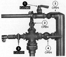
1. STATIC VENT COCK
2. STATIC SHUT-OFF VALVE
3. DYNAMIC VENT COCK
4. BYPASS VALVE
5. DYNAMIC SHUT-OFF VALVE
Figure 19-1. Venting routine, Step 1.
19A3. Venting the system. Do not vent the
system when the ship is submerged, as the
pressures increase approximately 1/2 pound
per square inch for each foot of submergence,
and the mercury will be blown out of the
manometer.
|
|
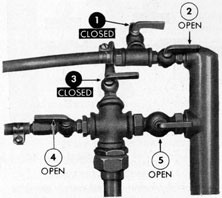
1. STATIC VENT COCK
2. STATIC SHUT-OFF VALVE
3. DYNAMIC VENT COCK
4. DYNAMIC SHUTOFF VALVE
5. BYPASS VALVE
Figure 19-2. Venting routine, Step 2.
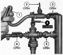
1. PINCH STATIC HOSE
2. STATIC VENT COCK
3. STATIC SHUT-OFF VALVE
4. DYNAMIC VENT COCK
5. BYPASS VALVE
6. DYNAMIC SHUT-OFF VALVE
Figure 19-3. Venting routine, Step 3.
|
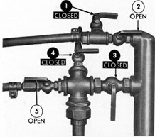
1. STATIC VENT COCK
2. STATIC SHUT-OFF VALVE
3. BYPASS VALVE
4. DYNAMIC VENT COCK
5. DYNAMIC SHUT-OFF VALVE
Figure 19-4. Valves and vent cocks in operating
positions.
For best results the ship should be stationary. The purpose of venting the system is
to remove any air that may be trapped in the
lines. The venting routine should be carried
out daily. The manometer should be gently
rocked back and forth in its gimbals while
venting to facilitate the removal of air. Vent
the system as follows: Turn the valves and
vent cocks as shown in Figure 19-1. When a
|
|
full stream of water, free from spitting, is
obtained from the dynamic vent cock, turn
the valves and vent cocks as shown in Figure
19-2. This is a transition step in the venting
routine. Turn the valves and vent cocks to
the positions shown in Figure 19-3. When a
full stream of water, free of spitting is obtained from the static vent cock, close the
static vent cock. The system is now vented,
and should be free of air. Turn the valves and
vent cocks to the operating position as shown
in Figure 19-4.
19A4. Lowering the rodmeter. To lower the
rodmeter, turn the hoist crank counterclockwise until the rodmeter is lowered to its
operating position. Keep the hose clear of
projections and chain links. The rodmeter is
in its operating position when the clamp and
guard assembly at the top of the rodmeter is
close to the sea valve extension.
19A5. Securing the log. Whenever the ship
enters port the log system is secured in the
following manner: Turn the hoist crank in a
clockwise direction until the top of the rodmeter is level with the marker plate, indicating that the tip of the rod is clear of the outer
hull. Keep the hose clear of projections as the
rodmeter is raised. The rodmeter may be
raised to its fully housed, or secured, position
by turning the crank until the top of the rodmeter strikes the stop at the top of the hoist.
|
