18A1. Description. A megger is an ohmmeter-type
instrument by means of which the
value of a resistance can be measured
and directly indicated by the position of a pointer on
a scale. The resistance indicated in an ohmmeter-type
instrument is independent of the
voltage applied for a test. The megger consists
of two principal elements: a hand-driven magneto type
direct current generator, which supplies the
current for making the measurement;
and the moving element with pointer, by means
of which the value of the resistance under
measurement is indicated.
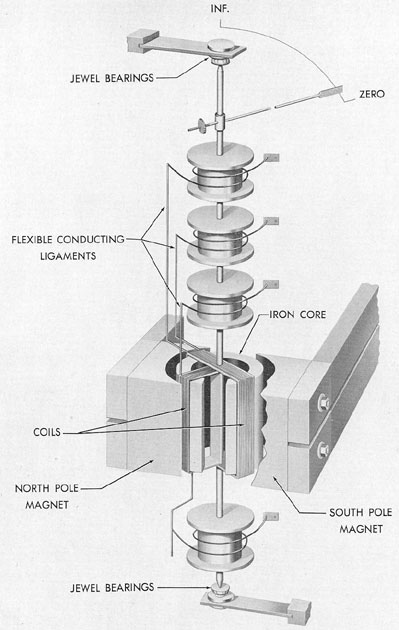
Figures 18-1 and 18-2 illustrate the construction
of the moving element and the magnetic circuit
and electrical connections in the
instrument. The permanent magnets serve for
both the ohmmeter and the generator. The
armature of the generator is hand-driven. The
rotational speed is stepped up through gears
and maintained at a constant rate, if a certain
cranking speed is exceeded, by means of a
clutching mechanism. The type III instrument
generates 500 volts and has a scale of 0 to 100
megohms.
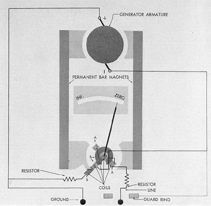
18A2. Principle of operation. The instrument
system consists primarily of two coils, A
and B (Figure 18-1), mounted on the same moving
element, with pointer attached, in a permanent
magnet field, Coil A is connected in series
with a resistance between the negative side of
the generator and the line terminal, and is called
the current coil. Coil B, in series with another
resistance, is connected across the generator
terminals, and is called the potential coil.
The moving element is mounted in spring-supported
jewel bearings and is free to rotate
about its axis, since there are no restraining or
controlling springs such as there are in an
ammeter or voltmeter. Current is led to the coils
by flexible conducting ligaments having the
least possible torsion, so that the pointer floats
over the scale. Hence, when the generator is not
being operated, the pointer may stand in any
position over the scale.
When current flows in coils A and B, they
tend to turn the moving element in opposite
directions. The pointer then takes a position
over the scale where the two forces are equal.
When the instrument is operated, either
with perfect insulation, or with nothing at all
connected across the earth and line terminals,
no current flows in coil A. The potential coil B
alone controls the movement and takes a position
opposite the gap in the C-shaped core, and
the pointer indicates infinity.
When, however, a resistance is connected
across the terminals, a current flows in coil A
and the corresponding torque draws the potential
coil B away from the infinity position into
a field of gradually increasing magnetic strength
until a balance is obtained between the forces
acting on the respective coils. Hence, by introducing
resistances of different known values
across the terminals and marking the
corresponding position of the pointer in each case, a
scale calibrated in resistance can be obtained.
Since changes in voltage affect both coils A
and B in the same proportion, the position of
the moving element is independent of the voltage. In the event that the instrument is short
circuited, the ballast resistance is sufficient to
protect the current coil.
The resistance range of meggers is very
great. For insulation resistance measurements,
their range is in thousands of megohms. They
are also designed to measure a resistance of only
a few ohms, such as the resistance to ground of
tower footings or ground wires. In service, the
megger is used for measuring insulation resistance
of cables, insulators, and windings of motors and generators.
To prevent the demagnetization of the
254
Figure 18-1. Megger magnetic circuit and electrical connections.
permanent magnets, a megger should never be connected
to a circuit in which current is flowing
and should not be placed on a pole piece or the
bedplate of a motor or generator.
18A3. Maintenance. The megger should be
given the same care and consideration as any
delicate instrument, as it contains a moving coil
with steel pivots turning in jewels and can be
injured by rough handling. There is an insulating
guard ring around each terminal post which
is wired to an internal circuit. This serves to
bypass around the moving coil element any
leakage current which may pass across the moist
or dirty surfaces of the box and which would
otherwise give an incorrect reading of the
circuit under test. The guard ring should be
maintained intact.
Care should be taken to keep the terminals
and terminal posts clean and the leads from
being partly broken, as such conditions would
add resistance to the circuit and give incorrect
readings.
There are no provisions for oiling any of
the bearings in the megger from the outside of
the case. The original assembly provides sufficient
lubrication for several years of use.
The megger has no external adjustments.
It can be checked for accuracy by shorting the
255
Figure 18-2. Megger moving element.
256
terminals, when it should read zero. With
terminals open, the pointer should stand at infinity
when the handle is turned at the usual speed.
Intermediate points of the scale can be checked
by measuring a known resistance, such as a voltmeter
of high range. Weston model No. 24 voltmeter averages
a resistance of about 100 ohms
per volt. The voltmeter should indicate about
160 volts at 120 rpm of the handle. A falling off
of the voltage generated does not affect the accuracy
of the megger, as the results are independent of the
test electromotive force. This
means that even though the permanent magnets
should change, or the speed of the turning vary,
the accuracy remains unaffected. However, if
the pointer stands at zero or infinity, as stated
above, the megger can be considered as being
fairly accurate. The pointer may stand anywhere
on the scale when the instrument is idle.
Repairs of any kind should be undertaken
only by an instrument maker who understands
the theory of operation, as the circuit resistances
have a certain relationship which must be maintained.
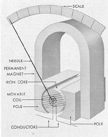
Figure 18-3. Operating principle of direct current
instruments.
B. AMMETERS AND VOLTMETERS
18B1. Description. The ammeters and voltmeters
supplied as part of the ship's measuring
instruments are direct current instruments.
Direct current instruments are fundamentally
current measuring devices and their indications or
calibration depend upon the characteristics of
the meter.
Ammeters and voltmeters are alike in construction
except for the fact that the coil of the
ammeter is wound with fewer turns of coarser
wire than the coil of the voltmeter. Thus the coil
of the ammeter is of lower resistance than the
coil of the voltmeter.
A coil with steel pivots and turning in jewel
bearings is mounted in a magnetic field which is
produced by permanent magnets. Motion of the
coil is restrained by two small flat coiled springs
which also serve to conduct the current to the
coil. The deflections of the coil are read with a
lightweight pointer which is attached to the coil
and moves over a graduated scale.
It is the force set up in the moving element
by the reaction between the permanent magnet
field and the field resulting from the current
flowing through the moving coil that causes
deflection and gives an indication of the current
or voltage being measured. An instrument of this
kind measures direct currents only.
18B2. Operating principle of direct current
instruments. If the moving coil of an ammeter
carries a current, a magnetic field results with
a north and a south pole at opposite ends of the
coil. If the coil carrying the current were placed
in a magnetic field, the coil would tend to turn
in such a direction that the resulting magnetic
field due to both the main field and that of the
coil would be at a maximum. Also the north
pole of the coil would be attracted toward the
south pole of the magnet, and the south pole
of the coil would be attracted to the north pole
of the magnet.
The moving coil of a direct current instrument
is made of several turns of wire carefully
insulated and wound upon a rectangular
257
aluminum frame. This coil is supported at the top
and bottom by hardened steel pivots turning in
cup-shaped jewels, usually sapphires. This
method of supporting the moving coil is almost
frictionless. The current is led in and out of the
coil by two flat spiral springs, one at the top of
the coil and the other at the bottom. These
springs also serve as the means of measuring
the force exerted by the current through the
moving coil and cause the pointer to return to
zero when current ceases to flow.
When current flows through the moving
coil, it rotates to a position where the force due
to the field of the coil is just equal to the returning force of the springs. The top and the
bottom springs are coiled in opposite directions
so that the effect of change of temperature,
which causes a spiral spring to coil or uncoil,
does not cause the needle to leave its zero
position. A light, delicate, aluminum pointer
is attached to the moving element to indicate the
deflection of the coil. This is carefully balanced
by small counterweights so that the whole moving
element holds its zero position very closely,
even if the instrument is not level. The pointer
moves over a graduated scale, marked in volts
or amperes as the case may be. Because of the
uniform radial field, the deflection of the
moving coil in this type of instrument is practically
proportional to the current in the moving coil
with the result that the scale of the instrument
has substantially uniform graduations.
If the moving coil, which is mounted on
jeweled bearings, starts to swing, it continues
swinging back and forth for some time, unless
it is in some way retarded or damped. One
method of damping is to attach an air vane to
the coil. This air vane is enclosed so that it
swings in a restricted space and damps any
swinging movement of the coil. The most satisfactory
method is electrical damping. If the coil
is wound on an aluminum bobbin, the motion
of the bobbin through the magnetic field induces
magnetic currents within itself in such a direction
as to put an electric load on the moving
coil. This opposes the motion of the coil and
thus brings the pointer to rest at the value to
be read. The pointer of a properly damped instrument moves quickly and comes to rest with
only about two or three overswings. Not only
does proper damping give faster readings, but
these slight oscillating swings serve to assure
the user of the instrument that there is no
frictional lag present.
From the foregoing we have learned that
the deflection of a direct current instrument is
a measure of the current passing through it.
The field of the moving coil tends to rotate the
coil to include as much of the flux from the
permanent magnet as possible. This motion is
opposed by the phosphor-bronze springs.
18B3. Operation of ammeters and voltmeters.
An ammeter, or the external ammeter
shunt, if there is one, is always placed in series
with the line, while voltmeters are placed in
shunt across the line. If the ammeter is used
with an external shunt, the shunt should have
the same serial number as the instrument, and
the calibrated leads, considered a part of the
instrument and furnished with it, should always
be used to connect the instrument to the shunt.
Ammeters ranging up to 50 amperes have self-contained
shunts, while ammeters for over 50
amperes usually have separate or external
shunts. Special care should be taken to see that
all contacts are clean, well-made and tight.
CAUTION. An ammeter should never be
connected across the line. Such a connection
would destroy the instrument.
18B4. Maintenance. Instruments should always be
carefully handled and any shock or
vibration avoided. In use, they should not be
placed in close proximity to any current-carrying
conductor or magnetic field. If more than
one instrument is used, they should be placed at
least 6 inches apart, to avoid mutual magnetic
effects. If the pointer does not read zero when
the current is off, use the zero adjuster to bring
the pointer to zero. By a quick side shift of the
instrument, it can readily be determined whether
the pointer or moving element is free from unusual
friction, and by turning about an axis of
rotation, whether it is out of balance.
The instruments require no oiling at any
time. The covers should always be kept free
from dust and dirt and the screws tightened
down to prevent dust from getting inside to the
258
working parts. The instruments at all times
should be carefully handled and kept in a dry,
clean locker under the charge of a responsible
man. Note that the instruments are sealed when
received. When the instruments have been repaired,
the seals should be renewed so that tampering
with the instrument can be detected.
Repairs and adjustments can readily be
made by a competent instrument man, but
owing to the fact that the instruments them
selves are used as the working or secondary
standards on shipboard, there is usually no
instrument of similar range available for checking
or calibrating them. For this reason, when an
instrument needs repairing or when there is any
doubt as to accuracy, it should be calibrated
by a tender that is equipped for this work, and
if that is impracticable it should be sent to a
navy yard for necessary repairs and calibration.
Likewise, after repairs or replacement of any
parts, a check must be made with a secondary
standard instrument and any adjustments necessary
to bring the meter within its guaranteed
accuracy should be made It should then be
sealed by the expert and returned to the vessel
from which it was received. Important secondary
standard instruments should be checked as
a regular routine at frequent intervals whenever
primary standards are available.
C. MILLIVOLTMETERS
18C1. Description. Ammeters and voltmeters
that are actuated by a few thousandths of a
volt are called millivoltmeters.
Millivoltmeters can be used as ammeters by
using a shunt across the coil. This shunt makes
it possible for the millivoltmeter to carry and
indicate a moderately large current. Only a small
fraction of the main current flows through the
moving coil.
Millivoltmeters can be used for measuring
voltage by placing a high resistance in series
with the moving coil. A high resistance connected
thus in series is generally known as a multiplier.