7A1. Purpose of a lubricant in a diesel engine. Lubricating oil in a diesel engine is used
for the following purposes:
1. To prevent metal-to-metal contact between moving parts.
2. To aid in engine cooling.
3. To form a seal between the piston rings
and the cylinder wall.
4. To aid in keeping the inside of cylinder
walls free of sludge and lacquer.
A direct metal-to-metal moving contact has
an action that is comparable to a filing action.
This filing action is due to minute irregularities
in the surfaces, and its harshness depends upon
the finish and the force of the contacting surfaces as well as on the relative hardness of the
materials used. Lubricating oil is used to fill
these minute irregularities and to form a film
seal between the sliding surfaces, thereby preventing high friction losses, rapid engine wear,
and many operating difficulties. Lack of this oil
film seal results in seized, or frozen pistons,
wiped bearings, and stuck piston rings. The high-pressures of air and fuel in diesel engines can
cause blow-by of exhaust gases between the
piston rings and cylinder liner unless lubricating
oil forms a seal between these parts.
Lubricating oil is used to assist in cooling
by transferring or carrying away heat from localized hot spots in the engine. Heat is carried
away from bearings, tops of the pistons, and
other engine parts by the lubricating oil. It is
the volume of lubricating oil being circulated
that makes cooling of an engine possible. For
example, under average conditions, an 8-inch by
10-inch cylinder requires about 24 drops of oil
per minute for lubrication of the cylinder wall.
About 30 drops of oil per minute normally will
lubricate a large bearing when the engine is
running at high speed. Yet some engines
circulate as much as 40 gallons of lubricating oil per
minute. This illustrates how much of the lubricating oil is used for cooling purposes.
Lubricating oil that is used to form a seal
between piston rings and cylinder walls or on
any other rubbing or sliding surface must meet
the following requirements:
1. The oil film must be of a sufficient thickness and strength, and must be maintained under
all conditions of operation.
2. The oil temperature attained during operation must be limited.
3. Under normal changing temperature
conditions the oil must remain stable.
4. The oil must not have a corrosive action
on metallic surfaces.
It is important not only that the proper
type of oil be selected but that it be supplied in
the proper quantities and at the proper temperature. Moreover, as impurities enter the system,
they must be removed. Diesel engines used in
the present fleet type submarines use a centralize pressure feed lubrication system. In this
system is incorporated an oil cooler or heat
exchanger in which the hot oil from the engine
transfers its heat to circulating fresh water. The
fresh water is then cooled by circulating sea
water inside the fresh water cooler. The heated
sea water is then piped overboard.
In order to maintain a strong oil film or
body under varying temperature conditions, a
lubricating oil must have stability. Stability of
the oil should be such that a proper oil film
is maintained throughout the entire operating
temperature range of the engine. Such a film
will insure sufficient oiliness or film strength between the piston and cylinder walls so that
partly burned fuel and exhaust gases cannot get
by the piston rings to form sludge.
7A2. Chemistry of lubricating oils. As explained in Chapter 5, lubricating oil is the
product of the fractional distillation of crude
129
petroleum. Lubricating oils obtained from certain types of crude petroleum are better adapted
for diesel engine use than others, therefore it
was formerly highly important that the oils be
manufactured from crudes that contained the
smallest possible percentage of undesirable constituents. Modern refining methods, by employing such processes as fractionation, filtration,
solvent refining, acid treating, and hydrogenation have, however, made it possible to produce
acceptable lubricating oils from almost any
type of crude oil.
7A3. Properties of lubricating oils. To insure satisfactory performance a lubricating oil
must have certain physical properties which are
determined by various types of tests. These tests
give some indication of how the oil may perform
in practice, although an actual service test is the
only criterion of the quality of the oil. Some of
the tests by which an oil is checked to conform
to Navy specifications are as follows:
1. Viscosity. The viscosity of an oil is the
measure of the internal friction of the fluid. Viscosity is generally considered to be the most
important property of a lubricating oil since
friction, wear, and oil consumption are more or
less dependent on this characteristic.
2. Pour point. The lowest temperature at
which an oil will barely pour from a container
is the pour point. High pour point lubricating
oils usually cause difficulty in starting in cold
weather due to the inability of the lubricating
oil pump to pump oil through the lubricating
system.
3. Carbon residue. The amount of carbon
left after the volatile matter in a lubricating oil
has been evaporated is known as the carbon
residue of an oil. The carbon residue test gives
an indication of the amount of carbon that may
be deposited in an engine. Excessive carbon in
an engine leads to operating difficulties.
4. Flash point. The lowest temperature at
which the vapors of a heated oil will flash is the
flash point of the oil. The flash point of an oil
is the fire hazard measure used in determining
storage dangers. Practically all lubricating oils
have flash points that are high enough to eliminate the fire hazard during storage in submarine,
tender, or base stowage facilities.
5. Corrosion. The tendency of an oil to corrode the engine parts is known as the corrosive
quality of the lubricating oil. The appearance of
a strip of sheet copper immersed in oil at 212 degrees F
for 3 hours formerly was thought to indicate the
corrosive tendency of an oil. This test, however,
is not necessarily a criterion of the corrosive
tendency of the newer compounded oils, some of
which do darken the copper strip but are not
corrosive in service. Corrosive oil has a tendency
to eat away the soft bearing metals, resulting
in serious damage to the bearing.
6. Water and sediment. Water and sediment in a lubricating oil normally are the result
of improper handling and stowage. Lubricating
oil should be free of water and sediment after
leaving the purifier and on arriving at the engine.
7. Acidity or neutralization number. The
neutralization number test indicates the amount
of potassium hydroxide, in milligrams, necessary
to neutralize one gram of the oil tested. It is,
therefore, proportional to the total organic and
mineral acid present. The results are apt to be
misleading or subject to incorrect interpretation,
since the test does not distinguish between corrosive and noncorrosive acids, both of which
be present. The chief harm resulting from
the presence of organic acid, which is noncorrosive, is its tendency to emulsify with water.
This emulsion picks up contaminants and is a
sludge which may interfere with proper oil circulation. The neutralization number of new oils
is generally so low as to be of no importance.
8. Emulsion. The ability of an oil to separate from water in service is known as the
emulsibility of the lubricating oil. The emulsibility of a new oil has little significance. Two
oils that have different emulsifying tendencies
when new, may have the same emulsion tendency after being used in an internal combustion
engine for a few hours. The emulsibility of an
oil that has been in use for some time is important.
9. Oiliness or film strength. The ability of
a lubricating oil to maintain lubrication between
sliding or moving surfaces under pressure and
at local high temperature areas is known as the
oiliness or film strength of the oil. Film strength
is the result of several oil properties, the most
important being viscosity.
130
10. Color. The color of a lubricating oil is
useful only for identification purposes and has
nothing to do with lubricating qualities. If the
color of a nonadditive oil is not uniform, it may
indicate the presence of impurities; however, in
additive lubricating oils, a nonuniform color
means nothing.
11. Ash. The ash content of an oil is a
measure of the amount of noncombustible material present that would cause abrasion or scoring of moving parts.
12. Gravity. The specific gravity of an oil
is not an index of its quality, but is useful for
weight and volume computation purposes only.
13. Sulphur. The test for sulphur indicates
the total sulphur content of the oil and does not
distinguish between the corrosive and noncorrosive forms. A certain amount of noncorrosive
sulphur compounds is allowable, but the corrosive compounds must be eliminated because of
their tendency to form acid when combined with
water vapor.
14. Detergency. The ability of an oil to
remove or prevent accumulation of carbon deposits is known as its detergent power.
7A4. Viscosity of lubricating oils. The viscosity of a lubricating oil at the operating temperature in the engine is one of the most
important considerations in selecting oil, since
viscosity is the characteristic that determines
film thickness and the ability to resist being
squeezed out. The viscosity of an oil changes
with temperature. Therefore, the viscosity
should be measured at the operating temperatures of that particular part of the engine which
the oil is to lubricate. From the viewpoint of
lubrication, engines can be considered in two
classes, those in which the cylinders and bearings are lubricated separately, and those in
which only one lubricating system is used. If
there are separate lubrication systems for cylinders and bearings, it is possible to use two
grades of oil, the heavy one for cylinders and a
medium one for bearings. The operating temperature to which the oil is subjected in the
cylinders is naturally much higher than in the
bearings. Also the motion in a cylinder is sliding, and a heavier oil is required to provide
sufficient body to prevent metallic contact and
wear. In the bearings, however, the temperatures are lower and the rotation tends to create
a fluid film permitting a lighter oil to be used.
When a single lubricating system supplies oil
to cylinders and bearings, it is necessary to
compromise on an oil that will do the best job
possible in both places. All modern submarine
diesel engines are of the latter type, having a
single lubricating system.
Temperature, however, is not the only consideration in selecting an oil of the proper viscosity. Clearances, speed, and pressures are also
important factors. Their effects on required viscosity may be summarized as follows:
The oil selected for a diesel engine is therefore a compromise between a high- and a low-viscosity oil. Most high-speed engines run better
using low-viscosity oils, but the viscosity must
not be so low that the oil film wedge is too thin
for efficient lubrication. On the other hand, oil
of a greater viscosity than necessary should not
be used because:
1. An oil of too great a viscosity increases
starting friction.
2. Increased friction raises oil temperatures, and thereby promotes oxidation.
3. The more viscous oils usually have a
higher carbon residue.
4. An oil of too great a viscosity places an
overload on the lubricating oil pump with a possible inadequate supply reaching some moving
parts.
For practical purposes the viscosity is determined by noting the number of seconds required for a given quantity of oil to flow through
a standard orifice at a definite temperature. For
light oils the viscosity is determined at 130 degrees F,
and for heavier oils at 210 degrees F. The Saybolt type
viscosimeter with a Universal orifice is used for
determining the viscosity of lubricating oils. The
longer it takes an oil to flow through the orifice,
at a given temperature, the heavier or more
viscous the oil is considered.
7A5. Tests. Viscosity tests are frequently
conducted on board ship to determine the
amount of dilution caused by leakage of fuel oil
131
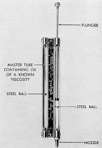
into the lubricating oil system. The test is made
with a Visgage (Figure 7-1), a small instrument
consisting of two glass tubes, each of which
contains a steel ball, and a scale calibrated to
indicate seconds Saybolt Universal (SSU) at
100 degrees F. One of the glass tubes is sealed and
contains oil of a known viscosity. The other has
a nozzle at one end and contains a plunger with
which the oil to be tested is drawn into the tube.
The instrument should be warmed by hand for
a few minutes so that the temperature of the
sample oil will be the same as that of the oil
sealed in the master tube. Then, starting with
both steel balls at the zero marking on the scale,
the instrument is tilted so that the balls will
move through the oil. On the instant that the
leading ball reaches the 200 marking at the end
of the scale, the position of the other ball in
relation to its scale is noted. That reading indicates the viscosity of the sample oil in SSU at
100 degrees F direct.
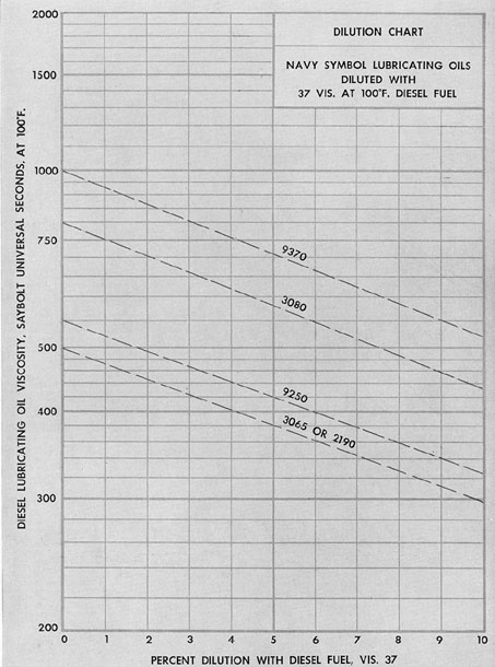
The percentage of dilution of the lubricating oil by the diesel fuel oil is determined by use
of the viscosity blending chart. This chart is
essentially a graph of oil viscosity against percentage. Both right and left vertical boundary
lines are marked in terms of viscosity SSU.
The horizontal lines are divided into percentages
from 0 to 100 percent. In using the viscosity
blending chart, a line is drawn between the
lubricating oil viscosity marked on the left vertical boundary line and the diesel fuel oil viscosity
marked on the right vertical boundary line. This
line represents only one particular lubricating oil
viscosity. Figure 7-2 is an expanded portion of
one section of a viscosity blending chart with
lines drawn in for Navy symbol lubricating oils
most commonly used. To determine the percent
dilution of a lubricating oil, the viscosity of a
test sample of the used oil is obtained, usually
with a Visgage. The intersection of this valve on
the chart with the line representing the Navy
symbol oil in use gives a direct reading of the
percentage of dilution on the horizontal scale.
Example:
SSU at 100 degrees F
New lubricating oil, viscosity 9250
550
Diesel fuel oil
37
Used lubricating oil (measured by Visgage)
420
Figure 7-1. Visgage.
As shown on the chart, the dilution is
approximately 5 percent.
7A6. Detergent lubricating oils. Detergent
or additive oils as they are usually called, consist
of a base mineral oil to which chemical additives
have been added. The additive agent has the following beneficial effect on the performance of
the base lubricant:
1. It acts as an oxidation inhibitor.
2. It improves the natural detergent property of the oil.
3. It improves the affinity of the oil for
metal surfaces.
For Navy use, heavy duty detergent lubricating oils of the 9000 series are used in most
diesel installations. The use of these oils in a
diesel engine results in a reduction in ring sticking and gum or varnish formation on the piston
and other parts of the engine. In dirty engines,
a heavy duty detergent oil will gradually remove
gummy and carbonaceous deposits. This material being carried in suspension in the oil will
132
Figure 7-2. Section of viscosity blending chart.
133
tend to clog the oil filters in a relatively short
time. Normally, a dirty engine will be purged
with one or two fillings of the sump, depending
upon the condition of the engine and the quantity of the oil used. During the cleaning-up process, the operator should drain the sump and
clean the filter if the oil gage indicates an inadequate oil flow.
In using additive or detergent type oils the
following points should be considered:
1. All Navy approved oils are miscible.
However, to obtain the maximum benefit from
additive oils, they should not be mixed with
straight mineral oils except in emergencies.
2. Detergent oils on the approved list are
not corrosive. Should ground surfaces be found
etched, or bearings corroded, it is probable that
contamination of the lubricant by water or partially burned fuel is responsible. It is important
that fuel systems be kept in good repair and
adjustment at all times. The presence of water
or partially burned fuel in lubricating oil is to be
avoided in any case, whether mineral oil or
detergent oil is used. However, small quantities
of water in the Navy symbol 9000 series oils are
no more harmful than the same amount of water
in straight mineral oils. They will not cause
foaming nor will the additives in the oils be
precipitated
7A7. Sludge. Almost any type of gummy or
carbonaceous material accumulated in the
power cylinder is termed sludge. The presence
of sludge is dangerous for several reasons:
1. Sludge may clog the oil pump screen or
collect at the end of the oil duct leading to a
bearing, thereby preventing sufficient oil from
reaching the parts to be lubricated.
2. Sludge will coat the inside of the crankcase, act as an insulation, blanket the heat inside
the engine, raise the oil temperature, and induce
oxidation.
3. Sludge will accumulate on the underside
of the pistons and insulate them, thereby raising
piston temperatures.
4. Sludge in lubricating oil also contributes
to piston ring sticking.
Sludge is usually formed by one or a combination of the following causes:
1. Carbon from combustion chambers.
2. Carbon caused by the evaporation of oil
on a hot surface, such as the underside of a
piston.
3. Gummy, partially burned fuel which
gets past the piston rings.
4. An emulsion of lubricating oil and water
which may have entered the system.
Sludge is often attributed to the breaking
down of lubricating oil, but generally this is not
true.
Sludge gathers many dangerous ingredients,
such as dust from the atmosphere, rust caused
by water condensation in the engine, and metallic particles caused by wear, which contribute to
premature wear of parts and eventual break
down of the engine.
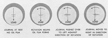
7A8. Bearing lubrication. The motion of a
journal in its bearing is rotary, and the oil tends
to build up a wedge under the journal. This oil
wedge lifts the journal and effectively prevents
metallic contact. The action of the oil film is
explained in Figure 7-3 which illustrates the
hydrodynamic theory of lubrication. This theory,
involving the complete separation of opposing
surfaces by a fluid film, is easily understood
when the mechanism of film formation in a plain
bearing is known. The diagram shows first the
bearing at rest with practically all of the lubricant squeezed from the load area. Then, as
rotation begins, an oil film is formed which
separates the journal from the bearing. When
rotation starts with the clearance space filled
with oil there is a tendency for the journal to
climb or roll up the bearing as a wheel rolls
uphill. As the center of the bearing does not
coincide with the center of the journal, the clearance space is in the form of a crescent with its
wedge-shaped ends on either side of the contact
or load area. Because of the fact that oil is
adhesive and sticks to the journal, rotation
causes oil to be drawn into the wedge-shaped
space ahead of the pressure area. As the speed
of rotation increases, more oil is carried into the
wedge by the revolving journal, and sufficient
hydraulic pressure is built up to separate completely the journal and bearing. When this film
has formed, the load on the journal tends to
134
Figure 7-3. Formation of bearing oil film.
cause it to drop to the lowest point. However,
the pressure built up in the converging film
ahead of the pressure area tends to push the
journal to the other side of the bearing. The
wedging action of the oil builds up a film pressure of several hundred pounds per square inch.
The oil pump pressure, however, need only be
sufficient to insure an adequate supply of oil to
the bearings. All oil openings should be in the
low-pressure section of the bearing in order to
keep the lubricating oil pump pressure to a
minimum. Diesel bearing pressures normally are
not much over 1000 psi, and an oil film of
straight mineral oil will usually withstand pressures of over 5000 psi.
The viscosity required to produce the
proper oil film thickness depends on several
factors. A rough or poor bearing needs a more
viscous oil than a smooth, properly fitted bearing. Bearing clearances should always be enough
to form an oil film of the proper thickness. Excessive bearing clearances reduce the oil pressure and only an excessively viscous oil will stay
between the bearing surfaces. The greater the
load on the bearing, the greater the oil viscosity
required to carry the load. On the other hand,
higher speeds permit a reduction in viscosity
since the high shaft rotation helps build up the
oil film pressure.
Bearing trouble and failure are usually attributable to improper lubrication. This may
result from either a lack of sufficient lubricant
or the use of an improper lubricant. Lack of
lubricant may be due to excessive bearing wear,
excessive bearing side clearance, low oil level,
low oil pressure, and plugged oil passages.
Failure, due to the use of an improper oil,
results not only from incorrect original lubricant,
but more frequently from continued use of an
oil that should be replaced. Viscosity, in particular, is subject to change due to bearing temperature variation, dilution by unburned fuel,
and oxidation. Bearing temperature variation is
controlled by the proper operation of the cooling
system. Lubricating oils may become corrosive
in service, due to contamination by products of
combustion or to inherent characteristics of the
oil itself. Bearing corrosion is, of course, most
likely to occur at high temperatures.
To insure against corrosion, the lubricating
oil should be changed frequently, especially if
oil temperatures are high or if easily corroded
bearing materials are used. A pitted bearing
usually indicates corrosion, which may be due to
fuel, lubricant, or water.
7A9. Cylinder lubrication. The oil supplied
to the cylinders must perform the following
functions:
1. Minimize wear and frictional losses.
2. Seal the cylinder pressures.
3. Act as coolant.
135
If no lubricant were employed, the metal
surfaces would rub on one another, wearing
away rapidly and producing high temperatures.
The cylinder oil must prevent, as much as possible, any metallic contact by maintaining a
lubricating film between the surfaces. Since oil
body, or viscosity, determines the resistance of
the oil against being squeezed out, it might seem
that the thicker the oil, the better. This holds
true in regard to wear, but there are other factors to be considered The body of the oil which
prevents the film from being removed from the
rubbing surfaces also provides a drag, resisting
motion of the piston and reducing the power output of the engine. In addition, an oil that is too
heavy does not flow readily, and spots on the
cylinder walls remote from the point of lubrication may remain dry, causing local wear. Very
heavy oils tend to remain too long on the piston
lands and in ring grooves. While this condition
may result in lower oil consumption, it will
eventually cause gumming due to oxidation of
the oil, and the final result will be sticky rings.
For cylinder lubrication, therefore, it is desirable
to use the lightest possible oil that will still keep
the cylinder walls and piston lubricated. Use of
a light oil will result in faster flow of the oil to
the parts requiring lubrication, reduce starting
wear, and minimize carbon deposits. This will
result in lower fuel consumption, lower temperatures, longer periods between overhauls, and
finally, lower total operating costs The lubricating oil consumption will probably be slightly
higher, but the saving in fuel alone will more
than make up for the additional lubricating oil
expense.
The sealing function of the oil is tied in
with its lubricating property. In order to make a
good seal, the oil must provide a film that will
not be blown out from between the ring face and
the cylinder wall nor from the clearance space
between the ring and the sides and back of the
ring groove. The effectiveness of this seal depends partly upon the size of the clearance
spaces. With a carefully fitted engine, in which
clearances are small, a light oil can be used
successfully. If the oil is heavy enough to provide a good seal, it will have a good margin of
safety for the requirement usually stressed, that
of preventing metallic contact.
The oil aids in cooling by transmitting heat
from the piston to the cylinder wall. To fulfill
this requirement the oil should be as light as
possible, since with light oils there is more movement in the oil film, a condition which aids the
transfer of heat.
7A10. Navy specifications and symbols for
lubricating oil. The symbol numbers used in
Navy lubricating oil classification tables are for
the ready identification of the oils as to use and
viscosity. Each number consists of four digits, of
which the first classifies the oil according to its
use, and the last three indicate its viscosity. For
example, the symbol 2250 indicates that the oil is
a force feed oil (viscosity measured at 130 degrees F)
and has a viscosity of 250 seconds Saybolt Universal. The following is a list of the classification
of lubrication oils as to use:
Series
Classification
Navy Symbol Examples
1000
Aviation oils
1065, 1080, 1100, 1120, 1150
2000
Forced feed oils (viscosity measured at 130 degrees F)
2075, 2110, 2135, 2190
3000
Forced feed oils (viscosity measured at 210 degrees F)
3065, 3080, 3100
4000
Compound marine engine oils
4065
5000
Mineral marine engine and cylinder wall oils
5065, 5150, 5190
6000
Compounded steam cylinder oil (tallow)
6135
7000
-
-
8000
Compounded air compressor cylinder oils
8190
9000
Compounded or additive type heavy duty lubricating oils (viscosity measured at 130 degrees F)
9110, 9170, 9250, 9370, 9500
136
The most common lubricating oil classification is that known as the SAE (Society of Auto
motive Engineers) classification. Since the SAE
numbers are more generally used outside of the
Navy, a comparison showing the viscosity limits
of the various numbers is given in the accompanying table.
SAE No.
Viscosity Seconds Saybolt
At 130 degrees F
At 210 degrees F
10
90-120
20
120-185
30
185-255
40
255-
80
50
80-105
60
105-125
70
125-150
B. LUBRICATING SYSTEMS
7B1. Basic requirements of a lubricating
system. Lubrication is perhaps the most important single factor in the successful operation
of diesel engines. Consequently, too much emphasis cannot be placed upon the importance of
the lubricating oil system and lubrication in
general. It is not only important that the proper
type of oil be used, but it must be supplied to
the engine in the proper quantities, at the proper
temperature, and provisions must be made to
remove any impurities as they enter the system.
In general, the basic requirements that a lubricating system must meet to perform its functions
satisfactorily are:
1. An effective lubricating system must correctly distribute a proper supply of oil to all
bearing surfaces.
2. It must supply sufficient oil for cooling
purposes to all parts requiring oil cooling.
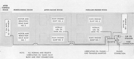
3. The system must provide tanks to
Figure 7-4. General arrangement of lubricating off tanks.
137
collect the oil that has been used for lubrication
and cooling, so that it can be recirculated
throughout the system.
4. The system must include coolers to
maintain the oil temperature within the most
efficient operating temperature range.
5. In order to exclude dirt and water from
the working parts of the engine, filters and
strainers must be included in the system to clean
the oil as it circulates.
6. Adequate facilities must be provided on
the ship for storing the required quantity of
lubricating oil necessary for extensive operation
and for transferring this oil to the engine lubricating systems as needed.
7B2. Ship's lubricating oil tanks and sumps.
A typical lubricating oil system installation on
recent submarines consists of three normal lubricating oil tanks and one reserve lubricating
oil tank. These tanks are located inside the pressure hull adjacent to the engineering spaces and
have approximately the following capacities:
Normal lubricating oil tank No. 1
1534 gallons
Normal lubricating oil tank No. 2
973 gallons
Normal lubricating oil tank No. 3
1092 gallons
Reserve lubricating oil tank
1264 gallons
In addition to these storage tanks, there is
a sump tank under each main engine and under
each of the two reduction gears. These tanks
collect the oil as it drains from the engine oil
pans. The sump tanks are always partially filled
in order to insure a constant supply of oil to the
lubricating oil pumps. As, the sump tanks are
never completely filled with lubricating oil,
their capacity is usually indicated as 75 percent
of the actual total tank capacity. The approximate capacities of the various sump tanks (at
75 percent) are:
Main engine sump tanks Nos. 1, 2, 3, 4
382 gallons each
Motor and reduction gear lubricating oil sumps Nos. 1, 2
165 gallons each
A filling connection is provided on the main
deck to a five-valve filling and transfer manifold
located on the starboard side of the forward engine room. This manifold is connected not only
to the filling connection, but also directly to each
of the normal lubricating oil tanks and the reserve lubricating oil tank. The oil to fill the
tanks normally is passed through a strainer before it reaches the filling and transfer manifold.
This oil strainer may be bypassed. A drain from
the bottom of the strainer makes it possible to
drain out any salt water that might have leaked
into the filling line through the outboard filling
connection.
The tanks are provided with vents and air
connections from the 225-pound air service lines.
By the use of these lines, lubricating oil may be
blown from any lubricating oil storage tank to
any other lubricating oil tank. Oil to be discharged may be blown or pumped overboard
through the deck filling connection or through a
hose connection in the filling line.
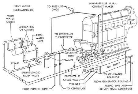
7B3. Operation of engine lubricating oil
system. Oil is drawn from the sump tank by
the attached lubricating oil pump. The discharge
from this pump passes through the lubricating
oil strainer. Between the discharge side of the
pump and the strainer is a relief valve built integral with the pump. From the strainer the oil
is carried to the lubricating oil cooler and thence
to the engine main lubricating oil headers. The
strainer is always placed forward of the cooler
in the system because, if the temperature of the
lubricating oil is higher, its filtering efficiency
will be greater and the power necessary to force
the oil through the strainer will be less.
In most installations the lubricating oil goes
from the main lube oil headers to the engine
main bearings and thence to the connecting rod
bearings. The oil then passes through a drilled
hole in the connecting rod up to the piston pin
bearing which it lubricates and sprays out onto
the under surface of the piston crown. Next, it
drains down into the oil drain pan, carrying
away from the piston much of the heat caused
by combustion. From the oil pan, the oil drains
to the engine sump tank from which it is recirculated
138
Figure 7-5. Typical lubricating oil flushing and filling system.
139
Between the oil pan and the sump tank,
screens and basket type strainers may be inserted to prevent small metallic particles from
draining down into the sump tank.
Lubricating oil for the main generator bearings is also provided by the main lubricating
oil system. The oil used for this purpose is piped
from the main lubricating oil line, at a point just
before it enters the engine oil header, to the
tops of the generator main bearings. From the
bottoms of the bearings, the oil drains back to
the sump tank, either directly or through the
engine oil system.
The attached lubricating oil pumps are
driven directly by the engines and therefore
cannot be used for priming the lubricating oil
system before starting. For this purpose, detached lubricating oil service pumps are provided, one in each engine room. These pumps
should be started approximately five minutes
before starting an engine. When an engine has
been started and its attached pump is supplying
oil to the engine system, the service pump may
be shut down. The service pumps may also be
used to circulate lubricating oil to cool an engine
after it has been stopped.
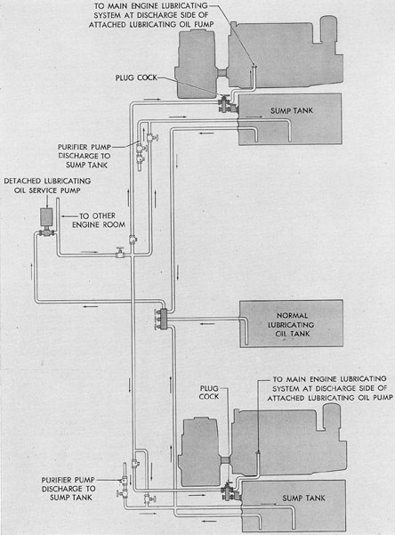
Figure 7-5 shows a typical lubricating oil
flushing and filling system in one engine room.
In this system the detached lubricating oil service pump may be used to prime the engine
lubricating oil systems prior to starting, to replenish the sump tanks from the normal lubricating oil stowage tank, and possibly to flush out
the engine lubricating oil system when necessary. When the system is used for priming, the
detached service pump takes a suction from the
sump tank and discharges the oil into the engine
lubricating oil system at the discharge side of
the attached lubricating oil pump. When the
detached pump is used for replenishing the
sump tanks, it takes a suction from the normal
lubricating oil tank and discharges the oil to
either sump tank as necessary.
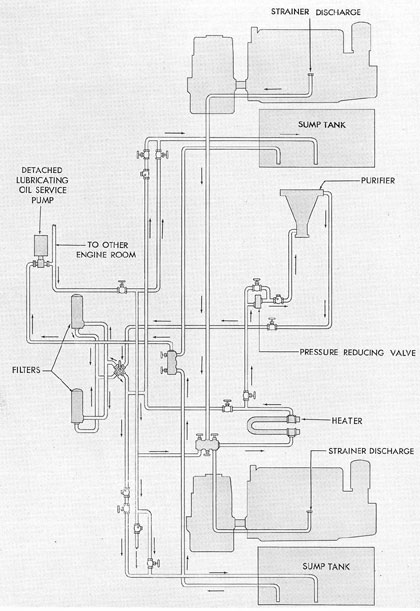
Lubricating oil may be purified by drawing
the oil from the sump tanks with the service
pump and discharging the oil back to the sump
tanks through a purifier. Figure 7-6 illustrates
a typical main engine lubricating oil purifying
system for one engine room. Two engines and
their respective sump tanks are shown, together
with the piping that connects these units with
the auxiliaries necessary for lubricating oil purification. These include a lubricating oil purifier,
detached lubricating oil service pump, lubricating oil heater, and lubricating oil filters. The
normal path of the oil during purification is
from the sump tanks to the lubricating oil service pump thence to the oil heater, the purifier,
the filters, and then back to the sump tanks. In
actual installations, the filling and flushing and
the purifying systems are combined in one system. For clarity the systems are separated as
shown in Figures 7-5 and 7-6.
The lubricating oil pumps are designed to
deliver considerably more oil than is normally
required to pass through the engines. This insures sufficient lubrication when changes in the
rate of oil flow occur because of cold starting,
changes in speed, changes in viscosity of the oil
due to heat, or increases in bearing clearances.
Pressure gages are placed in the system to
indicate the pressures of the lubricating oil
entering the strainer, leaving the strainer, and
entering the engine. Through a change in pressure readings at these gages, troubles such as
air binding of pumps, broken supply lines, or
dirty strainers may be localized and remedied.
The lubricating oil is cooled by fresh or
salt water circulating through an oil cooler. The
pressure of the lubricating oil is higher than the
pressure of the water so that, in the event of a
leak, water cannot enter the oil system.
7B4. Detached lubricating oil service and
standby pumps. All fleet type submarines use
a detached lubricating oil service pump in each
engine room for the purpose of supplying the
purifier, filling the sump tanks from the storage
tanks, and for flushing and priming the engine
lubricating oil system. These ships also have a
standby pump located in the maneuvering room
for the purpose of filling the lubricating oil storage tanks, discharging used oil from the ship,
and for transferring oil from one tank to an
other. This pump also serves to supply the main
motor bearings and reduction gears in the event
that the oil pressure in that system drops below
the safe operating limit, or the reduction gear
sump pumps become inoperative. Both the
140
Figure 7-6. Typical main engine lubricating oil purifying system in one engine room.
141
detached service and standby pumps are of the
positive displacement type, driven by electric
motors.
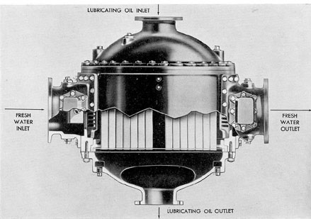
7B5. Lubricating oil coolers. The oil cooler
is a Harrison radiator heat exchanger. This
cooler is made up of a tube bundle or core and
an enclosing case. The tubes are oblong and
each tube encloses a baffled structure which
forms a winding passage for the flow of oil. The
tubes are fastened in place with a header plate
at each end and with an intermediate reinforcement plate. These plates are electroplated with
tin. The tube and plate assembly is mounted in
a bronze frame by means of which the tube
bundle is fastened to the covers on each end of
the casing.
The header plates, at the end of the tubes,
separate the water space in the casing from the
lubricating oil ports in the end covers. The lubricating oil flows through the tubes in a straight
path from one cover port to the other. The intermediate tube plate acts as a baffle to form a
U-shaped path for the water, which flows around
the outside of the tubes, from one opening in
the bottom of the casing to the other.
All the lubricating oil coolers are provided
with zincs which act as electrodes. Electrolytic
action is always present in all water systems on
a submarine, and these electrodes allow the zinc
rather than the cooler tubes to be eaten away.
Zincs are mounted on removable plates and
should be replaced when they show marked
deterioration.
In all cooling systems it is a universal rule
that the pressure of the liquid cooled be greater
than that of the cooling agent. In a lubricating
oil cooler this means that the pressure of the
lubricating oil should be greater than the pressure of the fresh or salt water, whichever is
used. If a leak should develop in the system, the
water would then be prevented from leaking
into the lubricating oil.
7B6. Lubricating oil strainers and filters.
a. General. Strainers and filters are incorporated in the lubricating oil system for removal
of foreign particles. In most installations the oil
is passed through two strainers located forward
of the cooler. Filters generally are located in the
lubricating oil purifying system on the discharge
side of the purifier. Various types of strainers
and filters may be found in service. Some
strainers consist of an element of edge-wound
metal ribbon, others use a series of edge type
disks. Filters may employ absorption type cellulose, waste, or wound yarn elements which are
replaced when dirty. A few of the commonly
used strainers and filters are described in the
following paragraphs.
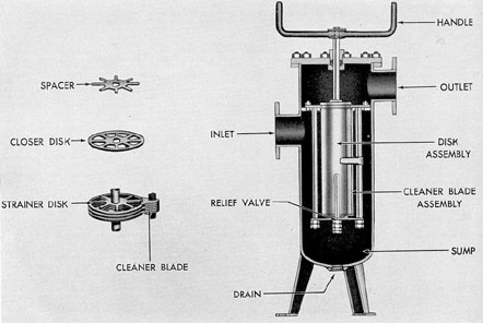
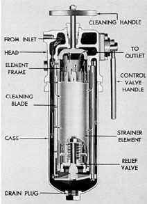
b. Edge disk type strainer. The edge disk
type of lubricating oil strainer consists of an assembly of thin strainer disks separated slightly
by spacer disks. The lower end of this assembly
is closed and the upper end is open to the
strainer discharge. The oil comes into the
strainer and is forced through the strainer disks
into the center of the strainer assembly. The oil
then passes up through the assembly and out
the top of the strainer. In passing through the
strainer, the oil must pass through the slots between the strainer disks. In the bottom of the
strainer element a relief valve is provided to
avoid the possibility of excess pressure building
up in the strainer should the slots become filled
with foreign matter. This relief valve bypasses
the oil up through the center of the strainer element and out the strainer discharge. The valve
is set to open when the differential pressure
reaches 10 psi. The disadvantage of this relief
valve is that its functioning allows any foreign
matter that may have collected in the bottom
of the strainer to pass to the discharge side of
the strainer and into the lubricating oil system.
When the assembly is turned by means of
the external handle, the solids that have lodged
against or between the disks are carried around
until they meet the stationary cleaner blades.
The stationary cleaner blades comb the solids
clear of the strainer surface. The solids are compacted by the action of the cleaner blades and
fall into the sump where they are filtered out
of the stream of incoming oil. To keep the
strainer in its clean and free filtering condition,
the external handle is given one or more complete turns in a clockwise direction at frequent
intervals. It is therefore not necessary to break
any connections or interrupt the flow of oil
through the strainer to clean the strainer unit.
142
Figure 7-7. Cutaway of latest type Harrison heat exchanger.
Figure 7-8. Cutaway of older type Harrison heat exchanger showing internal construction.
143
Figure 7-9. Edge disk type oil strainer.
If the handle turns hard it indicates that the
strainer surfaces have heavy deposits of solids
on them. The handle should be turned frequently; there is no danger of turning the handle
too often as there are no parts to wear out. If
the strainer cannot be cleaned by turning, the
head and disk assembly must be removed and
soaked in a solvent until the solids have been
removed. A wrench or other type of tool should
never be used to turn the strainer handle. During periods of overhaul the head and disk assembly should be removed and the disk assembly rinsed in a clean solvent. The disk assembly
should never be disassembled. If it is in such a
condition as to warrant disassembly it should be
replaced with a new unit. When cleaning the
disk assembly, the strainer body and sump
should be thoroughly drained and cleaned. Extreme care is necessary when cleaning the
strainer, to prevent injury to the strainer element and the introduction of dirt and foreign
material into the clean side of the strainer.
c. Edge-wound metal ribbon type strainer.
This strainer, manufactured by the Purolator
Company, is so constructed that the oil required
by the engine is continuously filtered except
when its filtering element must be removed for
cleaning or servicing. When this is done, the control valve handle is turned to the bypass position. This shunts the oil flow through the filter
head, permitting removal of the element without
interruption of oil flow to the engine. Under
normal conditions the oil comes into the
strainer and surrounds the ribbon element. It
then passes through and up the center of the
strainer element to the outlet passage. One
complete turn of the cleaning handle on top of
the element rotates the element winding, and
foreign material is removed from the element.
The element consists of a cage of accurately
spaced slots or perforations covered with a continuous, closely compressed coil of stainless steel
wire. The wire is passed between rollers to produce a wedge-shaped wire or ribbon, one edge
thicker than the other. On one side, projections
are spaced at definite intervals while the other
144
side is smooth. The projections on one side of
the wire touch against the smooth side of the
wire on the next coil to provide a spacing of
approximately 0.005 inch. The thick edge of
the wire is on the outside of the coil so that a
tapered slot is formed through the coil, with the
narrowest part of the slot on the outside. This
insures that the dirt particles small enough to
pass the outside, or narrowest point will not
become stuck halfway and clog the oil flow. The
dirt removed from the oil remains on the outside
and can readily be removed by rotation of the
cleaning handle.
The control valve handle on the strainer
operates the bypass valve. When the handle is
Figure 7-10. Cutaway of edge-wound metal
ribbon type oil strainer.
in the ON position, the lubricating oil is flowing
through the strainer. When the handle is in the
BYPASS position, the oil is flowing directly
through the head of the unit, and the strainer
case and element can be removed and cleaned.
The ON and BYPASS positions are indicated
on the strainer head.
The pressure drop through the strainer is
an indication of the condition of the straining
element. When the pressure drop becomes abnormal and cannot be reduced by turning the
cleaning handle, the strainer element should be
removed and cleaned with an approved solvent.
Care must be taken to prevent entrance of dirt
to the inside of the element while it is being
washed. The strainer element should not be
cleaned with a wire brush or a scraper. The
drain plug may be removed when the element
is bypassed, thereby making it possible to drain
out sludge and foreign material from the bottom
of the strainer.
Most filters of this type have a relief valve
installed in the lower end of the element. This
valve lifts when there is a differential pressure
of 7 to 10 psi. This design makes it possible for
dirt to be bypassed to the clean side of the filter;
therefore foreign matter must not be allowed to
accumulate in the filter housing.
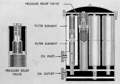
d. Absorption type filter. The absorption
type filter consists of a number of cellulose,
waste, or wound yarn filter elements supported
in a steel container. The steel container is partitioned so that oil entering the tank completely
surrounds all filter elements. A pressure relief
valve mounted in the partition is permanently
set to maintain the correct pressure differential
across the filter for proper clarification. Oil in
excess of the set pressure (usually about 20 psi)
is discharged through the valve and the filter
outlet from which it returns to the sump tank
for recirculation.
Filters of this type vary considerably in
design and construction but are similar in operating principle. Some designs employ only two
large filter elements, while others may have over
twenty. The location of the partition and the
position of the relief valve and the inlet and
outlet openings also vary depending upon the
make and model of the filter.
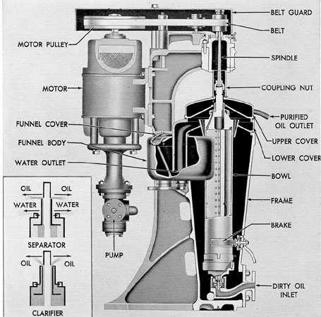
7B7. Lubricating oil clarifier. a. General.
Clarification of the lubricating oil is accomplished by the Sharples centrifuge which also
serves as the fuel oil purifier (Section 5C4).
The machine is set up as a clarifier by installing
145
Figure 7-11. Absorption type filter.
a clarifier sleeve, or ring dam, on the top of the
bowl, thus closing the outlet passage through
which the water is discharged. The term clarifier
is applied to the machine when it is set up to
discharge a single liquid from which solid matter
has been removed by centrifugal force. If the
machine is set up to separate two liquids from
solid matter and from each other (such as oil
and water in a fuel oil purifier) it is called a
separator. The machine is usually set up as a
separator for fuel oil purification and as a
clarifier for lubricating oil purification.
The lubricating oil purifier consists essentially of a rotor, or bowl, which rotates at high
speeds. It has an opening in the bottom to allow
the dirty lubricating oil to enter and two sets of
openings to allow the oil and water or the water
by itself to discharge. The bowl, or hollow rotor,
of the centrifuge is connected by a coupling unit
to a spindle which is suspended from a ball
bearing assembly. The pulley of this bearing assembly is driven by an endless belt from an
electric motor mounted on the rear of the frame.
Tension on the belt is maintained by an idler
pulley.
The lower end of the bowl is entered into
a drag bushing mounted in the drag assembly.
This is a flexibly mounted guide bushing. In
side the bowl is a three-wing partition consisting
of three flat plates equally spaced radially. The
three-wing partition rotates with the bowl and
its purpose is to force the liquid in the bowl to
rotate at the same speed as the bowl. The liquid
to be centrifuged is fed into the bottom of the
bowl through the feed nozzle under pressure so
that it jets into the bowl in a stream. For lubricating oil clarification the three-wing partition
has a cone on the bottom against which the feed
jet strikes to bring the liquid up to speed
smoothly without making an emulsion. This
cone is not necessary for fuel oil separation
since fuel does not have the tendency to
emulsify.
b. Operation. When a mixture of oil,
water, and dirt stands undisturbed, gravity tends
to effect a separation into an upper layer of oil,
146
an intermediate layer of water, and a lower
layer of the solid. When the mixture is placed
in a rapidly revolving centrifugal bowl, the effect of gravity is negligible in comparison with
that of centrifugal force, which acts at a right
angle to the vertical axis of rotation of the
bowl. The mixture tends to separate into a layer
of solids against the periphery of the bowl, an
intermediate layer of water, and a layer of oil
on the inner surface of the water. The discharge
holes of the bowl may be so arranged that water
can be drawn off and discharged into the upper
cover. The solids will deposit against the wall
of the bowl, to be cleaned out when necessary
or as operations permit.
If an oil contains no moisture, it need only
be clarified, since the solids will deposit in the
bowl, and the oil will discharge in a purified
state. If, however, the oil contains some moisture,
the continued feeding of wet oil to the bowl
Figure 7-12. Cross section of Sharpies purifier.
147
results eventually in a bowl filled with water, and
from that time on, the centrifuge is not accomplishing any separation of the water from the
oil. Even before the bowl is completely filled
with water, the presence of a layer of water in
the bowl reduces the depth of the oil layer. As
a result, the incoming oil passes through the
bowl at a very high velocity. This higher velocity means that the liquid is under centrifugal
force for a shorter time, and the separation of
water from the oil is, therefore, not so complete
as it would be if the bowl were without the
water layer, or if the water layer were a shallow
one. Because of this, the centrifuge should not
be operated as a clarifier unless the oil contains
very little or no water. A small amount of water
can be satisfactorily accumulated, together with
the solids, to be drained out when the bowl is
stopped for cleaning, but if there is any appreciable amount of water in the oil, the bowl
should be operated as a separator.
The length of time required to clarify lubricating oil is determined to a great extent by
the viscosity of the oil. The more viscous the oil,
the longer it takes to purify it to a given degree
of purity. The use of a pressure in excess of that
normally used to force a high-viscosity oil
through the purifier will result merely in less
efficient purification. Decreasing the viscosity of
the oil by heating is therefore one of the most
effective methods of facilitating purification.
The capacity rating of the centrifuge is
based on the use of 2190 oil at 130 degrees F, which
represents a viscosity of approximately 200
SSU. For good results no oil should be purified
at a higher viscosity than this and other oils
may need to be heated above 130 degrees F to reach
200 SSU. (See temperature table below.)
A reduction in the pressure at which the oil
is forced into the centrifuge will increase the
length of time the oil is under the influence of
centrifugal force, and therefore will tend to Improve results. The effective output of the machine in any case will depend on viscosity,
pressure, the size of the solid particles, the difference in specific gravity between the oil and
the water, and the tendency of the oil to emulsify. If a used lubricating oil contains no water,
but merely metallic particles, it may be cleaned
at a higher rate (high input pressure). If the
same oil contains a large percentage of water,
and has a tendency to emulsify, the input pressure will necessarily have to be lower to obtain
the required degree of purity.
TEMPERATURE TABLE
Oil, Navy symbol
Temperature* in degrees F
Oil, Navy symbol
Temperature* in degrees F
Oil, Navy symbol
Temperature* in degrees F
1042
89
2135
116
5065
143
1047
102
2190
129
5150
190
1065
137
2250
142
5190
209
1080
151
3050
119
6135
192
1100
166
3065
135
7105
173
1120
179
3080
154
8190
128
1150
190
3100
163
9170
123
2075
92
3120
180
9250
140
2110
95
4065
140
9370
158
* Minimum temperature of oil to obtain viscosity of 200 SSU
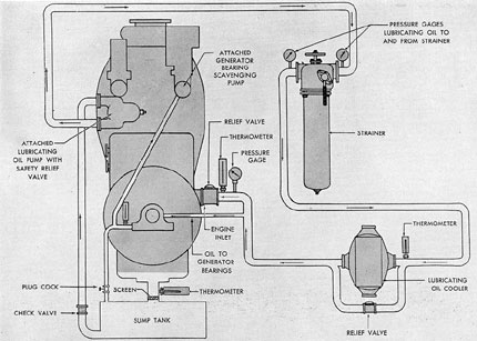
C. GENERAL MOTORS LUBRICATING SYSTEM
Oil for the GM
lubricating system is circulated by the positive
displacement attached lubricating oil pump
driven through the camshaft drive gear train.
This pump draws oil from the sump tank,
passes it through a safety relief valve at the discharge side of the pump, then through a lubricating oil strainer and a cooler. From the cooler,
the oil enters the engine's main lubricating oil
manifold. After circulating through the various
148
Figure 7-13. Lubricating oil system, GM.
passages in the engine, the oil drains into the
engine oil pan and then back into the sump
tank from which it is recirculated.
Oil for the generator bearings is taken from
the lubricating oil piping between the cooler
and the engine inlet. When the engine is running, the bearing drains are placed under a suction head by the attached generator bearing
scavenging pump to prevent flooding of the main
generator bearings. The plug cock in the gravity
drain line leading from the generator bearings
to the sump tank is closed and the oil is drawn
from the bearing drains into the engine lubricating system, whence it drains into the oil pan
and back to the sump tank. Before starting, or
when flushing the engine with the detached lubricating oil service pump, the plug cock in the
gravity drain line is opened, permitting the oil
to drain directly into the sump tank.
Mercury type thermometers are located at
the lubricating oil cooler inlet and at the engine
inlet. A bypass line with a relief valve is provided to bypass the cooler when for any reason
the cooler cannot handle the full flow volume.
This bypass is also used when cooling of the
oil is not required, as when starting an engine
in cold weather.
Engines on SS 313 to 318 have a relief
valve set at 80 psi. All other engines for the
SS 313 Class have a 30-pound differential pressure relief valve. The 80-pound relief valve is
not considered satisfactory for this service.
Duplex type pressure gages are provided
in the system to register the oil pressure at the
engine inlet and at the inlet and outlet of the
lubricating oil strainer. The system is provided
with a low-pressure alarm consisting of a pressurestat at the engine inlet which energizes a
horn and light whenever the oil intake drops to
15 psi or less. Continuous reading type thermometers indicate the temperature of the oil
drain from the engine and the generator
bearings.
149
Figure 7-15. Crankshaft oil passages, GM.
7C2. Engine lubricating system. The lubricating oil enters the engine at a connection on
the control side of the camshaft drive housing.
The relief valve ahead of the inlet keeps the
pressure of the oil at 40-50 psi. Any oil bypassed
by the relief valve returns to the camshaft drive
housing from which it drains to the oil pan.
From the engine inlet connection, the oil
flows to the main lubricating oil manifold which
extends the length of the engine and is bolted
to the bottom of the main bearing supports. The
oil flows from the manifold up through drilled
passages in the supports to each main bearing.
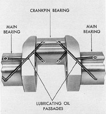
The crankpin bearings are lubricated with oil
that is received from the adjacent main bearings
through oil passages in the crankshaft. A drilled
passage in the connecting rod conducts this oil
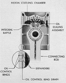
to the piston pin bearing and to the piston cooling chamber formed by an integral baffle under
the piston crown. Lubricating oil under pressure
flows from the top of the connecting rod, through
an oil sealing assembly and into the cooling
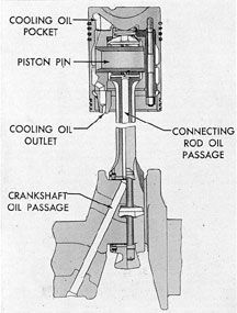
Figure 7-16. Piston and piston pin lubrication
and cooling, GM.
chamber. The sealing assembly consists of a
bronze oil seal saddle which rides on the machined top of the connecting rod and is held
against the connecting rod by a spring. The
heated oil overflows through two openings in
the integral baffle and down to the oil pan from
which it drains to the sump tank.
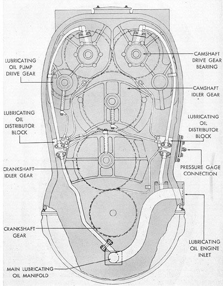
The lubricating oil for the camshaft drive
gear train is supplied by branch lines from the
main lubricating oil manifold. These branch
lines conduct oil to the lubricating oil distributor
block on each side of the camshaft drive housing. From each of the distributor blocks a pipe
supplies oil to each camshaft drive gear bearing.
The drilled camshafts are supplied with oil
through passages in the camshaft gear hubs and
the camshaft drive sleeves. The oil then passes
through the hollow camshafts and supplies the
camshaft bearings by radial holes through the
camshaft bearing journals. Oil for lubricating
the rocker levers and cam rollers flows through
a tube from the camshaft bearing cap at each
engine cylinder. This oil also lubricates the
valve assemblies. The oil flows from the end of
the camshafts down the camshaft drain tubes to
the engine oil pan.
Each rocker lever assembly is lubricated
with oil that is received from an adjacent camshaft bearing. The oil flows from the top of the
camshaft bearing through a tube to the plate
connection that is fastened to one end of the
rocker lever shaft. From this connection, the oil
flows through drilled passages in the rocker
lever shaft to the three bearings in the rocker
lever hubs.
A drilled passage in each of the rocker lever
forgings conducts the lubricating oil from a hole
in the hub bushing to the camshaft end of the
lever. The rocker lever motion permits oil to
flow intermittently under pressure from the
hole in the shaft, through one hole in the bushing and rocker lever to the cam roller. The bearing in each of the cam rollers receives oil
through drilled holes in the roller pin and in the
bearing bushings.
Oil from the cylinder heads and valve
operating gear drains through the micrometer
link passages to the control shaft compartment
and thence through tubes to the crankcase.
A manifold, bolted to the blower end of the
main lubricating oil manifold, supplies the lubricating oil for the blower gears and bearings,
and the accessory drive gears and bearings. The
manifold carries oil to the blower rear end plate,
to the blower front end plate, and the accessory
drive housing. Steel tubing cast into the ribs of
the end plates and the housing carries the lubricating oil to the blower drive gear bearings
and to the gear bearings in the accessory drive.
Excess oil drains through the lower blower housing into the oil pan.
The engine main lubricating system also
furnishes lubricating oil to the overspeed governor. When the engine speed exceeds a predetermined limit, this lubricating oil is pumped
under pressure to the overspeed injector lock
on each cylinder head and prevents the injector
from operating.
152
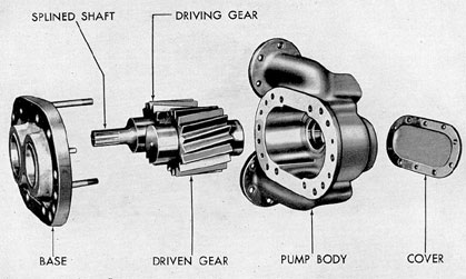
7C3. Attached lubricating oil pump. The
lubricating oil pump used for the GM pressure
lubricating system is mounted on the camshaft
drive housing cover and is a positive displacement helical spur gear type pump.
The lubricating oil pump body and body
base are bronze castings. The spur gears and
shafts are integral forgings and the shafts revolve on bronze bushings which are pressed into
the housing and cover, the cover being used to
close the outside of the body.
The spur gear that does the driving has its
shaft extended and splined to fit into the hub of
the oil pump drive gear. The camshaft drive
gear meshes with the oil pump drive gear to
operate the pump.
A spring-loaded pressure safety valve is frequently attached to the lubricating oil pump
to prevent the lubricating oil pressure in the
system from exceeding a safe operating pressure,
The spring pressure is adjusted with a regulating
screw which is enclosed by a cover on the valve
head. The regulating screw is adjusted so that
the valve opens when the lubricating oil discharged from the pump reaches a gage pressure
of 90 pounds. The bypassed oil is returned to
the suction side of the pump.
D. FAIRBANKS-MORSE LUBRICATING SYSTEM
7D1. General description. The lubricating
oil system outside the engine in an F-M installation is similar to the GM system described in
section 7C1. Lubricating oil is drawn from the
sump tank by the attached positive displacement gear pump mounted on a plate at the control end of the engine and driven by the lower
crankshaft through gears and a flexible coupling.
From the attached pump, the oil is passed
through a strainer and two coolers. Leaving the
coolers, the oil is piped to the engine where it
enters the lower lubricating oil header through
an inlet flange. A pipe connection ahead of the
engine inlet supplies lubricating oil to the generator bearings. After circulating through the
engine, the lubricating oil drains into the engine
oil pan and back to the sump tank for recirculation. Oil from the generator bearings returns directly to the sump tank.
An electrical resistance thermometer bulb
is installed in the lubricating oil line between
the pump and the strainer. Temperature of the
oil at this point is indicated on a gage mounted
on the engine gage board. This gage board also
supports a duplex type pressure gage which indicates the pressure of the oil in the line between the strainer and the attached pump and
in the line ahead of the engine inlet. Also near
the lubricating oil inlet to the engine is a mercury bulb thermometer and a pressure static
contact maker which closes a circuit to energize
a low-pressure alarm signal whenever the lubricating oil pressure drops to 15 psi or less.
The coolers may be bypassed if the operating conditions warrant. In this bypass line a
spring-loaded pressure relief valve, set to open
at a pressure of 45 psi, is installed. This bypass
and relief valve insures circulation of the oil
should its viscosity be such as to cause a restricted flow through the coolers.
7D2. Engine lubricating system. Entering
the lower lubricating oil header from the inlet
near the control end, the oil flows through the
lower header toward the blower end. There, a
vertical pipe carries the oil to the upper header.
Both headers extend longitudinally the entire
length of the engine.
Through supply pipes from both lower and
upper headers, oil is forced to each main bearing, and thence, through tubes swedged into the
crankshaft, to each crankpin bearing. From each
crankpin bearing, oil passes through the drilled
passage in the connecting rod to the piston pin
bearings and to the piston oil cooling pockets.
The surfaces between the thrust shells and
the crankshaft flanges are lubricated through
openings in the thrust bearing shells.
The cooling oil from each lower piston is
discharged through the lower piston cooling oil
outlet into the oil pan. Oil from each upper
153
Figure 7-19. Lubricating system, F-M.
piston is discharged through the upper piston
cooling outlet into the compartment around the
tipper ends of the cylinders. This oil can drain
either to the blower or to the control end of the
engine and then down to the oil pan.
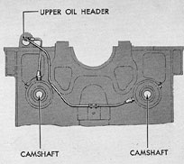
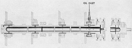
The two camshafts receive lubrication
from the upper oil header. Oil enters the hollow
camshafts through the camshaft bearing at the
control end of the engine, and small openings at
each bearing journal allow oil to reach the camshaft bearing surfaces. An opening in the end of
each camshaft, and excess oil from the No. 1
main bearing, supply oil to the timing chain at
the control end of the engine. The oil spray
from the timing chain provides lubrication for
the bearings of the idler sprockets, for the control mechanisms, drive gears, and bearings of
the governor, and for the water, fuel, and lubricating oil pumps. Spray from the timing chain
also lubricates the air start distributor and the
air start control valve located in the lower part
of the control end compartment. The air start
distributor valves admit a minute quantity of
oil which is carried by the air to lubricate the
air start check valves.
The drive bushings of the pump flexible
drive (on the control end of the lower crankshaft) receive lubrication through an opening in
the lower crankshaft from the control end main
bearing.
Oil from the upper engine compartment
enters the injection pump housing and lubricates the tappet assembly. The excess oil is
drained through leads to a return header which
conducts the oil to the control end compartment.
The blower drive gears are lubricated by
sprays of oil from special nozzles located on
each side of the centerline of the engine. These
nozzles are attached to the oil piping connecting
the lower and upper oil headers.
The blower flexible drive gear is lubricated
through openings in the drive spider. Oil is
brought to these openings from the nearest
main bearing by means of drilled passages in
the upper crankshaft.
Figure 7-21. Sectional views of F-M piston showing oil passages.
Figure 7-22. Thrust bearing oil passages, F-M.
155
Figure 7-23. Piston assembly oil passages, F-M.
The inner and outer blower impeller bearings are lubricated by branches and oil tubes
from the upper oil header.
The vertical drive gears and pinions are
lubricated by a spray of oil from nozzles connected to the upper and lower oil headers by
Figure 7-24. Oil supply to camshafts, F-M.
Figure 7-25. Camshaft and camshaft bearing lubrication, F-M.
156
Figure 7-26. Drive end of attached lubricating oil pump, F-M.
Figure 7-27. Gear end of attached lubricating oil pump, F-M.
157
tubes. Other tubes supply oil to the vertical
drive pinion shaft roller and thrust bearings.
Having performed its various functions.
the lubricating oil drips down into the oil pan
below the lower crankshaft. From the oil pan,
the oil drains into the sump tank from which
it is recirculated.
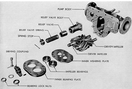
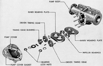
7D3. Attacked lubricating oil pump. The
attached lubricating oil pump used in the F-M
pressure lubricating system is mounted on a
pump mounting plate on the control end of the
engine. It is driven, through gears and a flexible
coupling, by the lower crankshaft. The pump is
a positive displacement herringbone (impeller)
gear type and consists essentially of a pump
body, a driver and driven timing gear, a driver
and driven impeller, inner and outer wearing
plates, and inner and outer bearing plates. A
spring-loaded relief valve, set at 50 to 60
pounds pressure, is located in the discharge
opening of the pump body.
The impeller shafts are supported on bearings pressed into the bearing plates. The inner
and outer wearing plates are located against
the inner surfaces of the bearing plates and
provide a clearance of 0.002 to 0.004 inch between the wearing plates and the impellers.
The longitudinal clearance between the impellers and the pump body is 0.003 to 0.0045 inch.
The driver timing gear is pressed on the end
of the driver impeller shaft and the driven timing gear is pressed on the end of the driven impeller. Both timing gears are enclosed within
the pump cover. The drive coupling is attached
to the end of the driver impeller outside the
outer bearing plate.