13A1. Function and type. The main diesel
engines are directly connected to the main generators which furnish power to the main motors
or battery through the control cubicle. Two
types of main drive installations are now in use
in modern fleet type submarines. The older type
which is at present used in about 95 percent of
our submarines consists of four main motors arranged in pairs to drive each of the propeller
shafts through a reduction gear. This type of
installation uses a single control cubicle. The
latest type of main drive installation consists of
a split control cubicle and two large, slow-speed,
double-armature motors which are directly connected to the propeller shaft. Each section of the
split control cubicle is designed primarily to
control propulsion on its particular side. It is
possible, however, to tie the two sides of the
split cubicle together and therefore use port
engines on the starboard screw and vice versa.
This description of reduction gears is limited to the older type installation. Each reduction gear reduces the high main motor speed of
approximately 1300 rpm to the propeller shaft
speed of 280 rpm. The ratio of reduction is
determined by the maximum efficiency obtainable from the propellers without loss of power
at varying motor and propeller speeds.
The gears are single reduction, double helical type, a right- and left-hand helix being used
to balance the fore and aft components of the
tooth pressure. These helical gears produce a
smoother action and avoid the tooth check of
spur gears.
13A2. Description and operation. With the
exception of minor differences in design, gear
units produced by various manufacturers and
installed on fleet type submarines today are
similar. Specifications to which they are built
will be found in the manufacturer's instruction
book pertaining to the unit in question. The two
units used on each ship are alike except that
one is for port propulsion and the other for starboard propulsion. Facing aft, the port shaft
rotates clockwise, and the starboard shaft rotates counterclockwise.
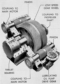
The reduction gear assembly consists essentially of two main motor pinions forged and
cut integral with the pinion shafts, one main
gear or bull gear which is connected to the
propeller shaft, and a lubricating oil pump gear
which is geared to the inner pinion shaft. The
forward ends of the pinion shafts are connected
to their respective motors through flexible couplings. Each pinion shaft is supported by a cylindrical type bearing at each end.
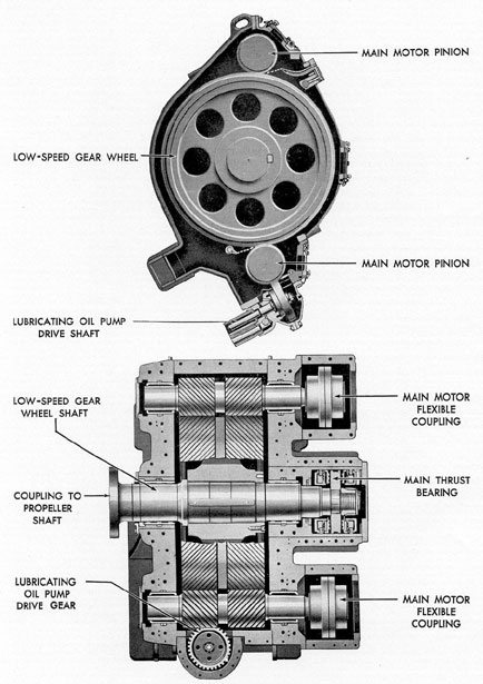
The main gear is pressed and keyed to the
gear shaft. The aft end of the shaft is coupled
to the propeller shaft. On the forward end of
the main gear shaft is mounted the collar of the
main thrust bearing which absorbs the propeller
thrust. The gear and shaft are carried on two
sleeve bearings.
The sleeve bearings consist of steel shells
lined with babbitt. The bearing shells are split
Figure 13-1. Reduction gear, top case removed.
261
Figure 13-2. Sectional views of reduction gear.
262
and the two halves of each shell are held in
alignment by dowels set in the lower half.
Dowels in the bearing caps prevent the shells
from rotating. The lubrication of the bearings is
explained in Section 13A4f.
13A3. Flexible couplings between pinion and
motor shafts. The couplings between the two
main motor armature shafts and the pinion
shafts of the reduction gear are of the enclosed
flexible type. Each coupling consists essentially
of two hubs with external spur gears, and two
sleeves with internal spur gears. The hubs are
pressed on and keyed to their respective shafts.
The floating sleeves fit around the hubs so that
the spur gear teeth are permanently meshed.
The floating sleeves are bolted together.
This type of coupling provides longitudinal
flexibility between the driving and driven shafts
and thereby permits the pinion to trail the main
gear. Movement of the main gear is in turn limited by the clearance in the thrust bearing. The
coupling permits a small amount of misalignment of the hubs to occur without causing operational difficulties. However, it is not advisable
to operate continuously with the hubs out of
alignment because the coupling is not intended
to function as a universal joint. Continuous operation with the hubs out of alignment will result
in excessive friction and gear teeth wear, and
eventually will cause a breakdown.
The couplings are lubricated by a continuous stream of oil supplied by the main motor
and reduction gear lubricating oil pump. Oil
enters through a nozzle and after passing between the gear teeth is discharged through holes
in the sleeve.
13A4. Maintenance. a. Machinery history. It
is of great importance that the machinery history contain a complete record of the installation from the time of commissioning. Complete
installation data as furnished by the contractor
should be entered in the machinery index by
prospective engineer officers at the contractor's
yard. This should include the original bearing
crown thickness or bridge gage readings, bearing
clearances, thrust settings and clearances, and
tooth clearances (backlash and root) of the gear
wheel and pinion teeth. It is essential that these
data be on hand when the alignment is subsequently checked.
An accurate record of all repairs, adjustments, readings, and casualties should be kept
in the machinery history.
b. Unusual sounds. A properly operating
reduction gear has a certain definite sound
which the trained operator can easily recognize.
The cause of any unusual noises should be
investigated, and the gears should be operated
with caution until the source is located and
remedied.
c. Tooth contact. It is essential, for proper
operation of the gears, that the total tooth pressure be uniformly distributed over the total area
of the tooth faces. This is accomplished by accurate alignment, and adherence to the designed
clearance limits.
Alignment should be checked at the time
the gear is installed, during each major overhaul, and after any casualty severe enough to
threaten the alignment. Operating gears with
faulty alignment are detrimental to the life and
performance of the teeth. Continued quiet operation and good tooth contact are the best indications of proper tooth alignment.
d. Backlash. Backlash is measured by locking the main gear in its forward position and
then moving each pinion just far enough forward and aft to make firm contact each way.
The total lengthwise movement measured when
doing this is the axial backlash. The backlash
will increase with wear, and it can increase
considerably without causing trouble. The actual
longitudinal movement, as measured at the time
the unit was built at the factory, should be found
stamped on all pinion shafts except spares, and
should be recorded in the machinery history.
This measurement is the minimum allowable
backlash.
e. Flexible couplings. The coupling backlash should be checked at regular intervals to
see that it has not increased excessively. A dial
indicator is used to measure the total backlash
without dismantling the coupling. The one shaft
is held stationary, and the dial indicator is
mounted on the opposite or moving shaft with
the indicator needle on some Dart of the coupling housing. By twisting the movable shaft
back and forth without allowing the stationary
shaft to move, the total backlash will be indicated on the dial indicator.
263
The backlash when found should be
checked with the recorded initial backlash. If
subsequent wear has increased the backlash to
twice the original amount, replacement of the
coupling should be considered.
Since the condition of the bearing surfaces
depends upon the axial alignment of the shafts,
regular inspection should include a check to see
that proper alignment is maintained. To check
the alignment, the flexible coupling must first
be dismantled. To accomplish this, the manufacturer's instruction book should be consulted.
f. Bearings. All of the bearing caps may be
removed for bearing inspection or replacement
without disturbing the gear case. The pinions
are light enough so that no trouble should be
experienced when rolling out the lower halves
of the pinion bearings once the shaft has been
raised.
When assembling, all bearing shells should
be replaced in their original positions. Old
cement should be cleaned off the mating surfaces of the bearing caps, end caps, and case,
and a new coat of oilproof cement applied to
these surfaces before reassembling. Do not permit the cement to contact the surface of the
bearing. The dowel bolts should be tapped back
into position before the bearing cap bolts are
tightened.
Before starting the gear unit, sufficient oil
should be pumped through the system by the
standby pump to indicate pressures not less
than 15 pounds on the two gages and to show
steady flow through the thrust bearing sight
flow indicator.
After starting the unit and securing the
standby pump, the oil inlet temperature should
not exceed 130 degrees F. Bearing temperatures should
not exceed 180 degrees F, and the temperature rise
should not exceed 50 degrees F. At full speed, lubricating oil pressure at the reduction gears should be
at least 15 pounds. At any value above 25 percent of full speed, the pressure should not fall
below 4 pounds. For continuous operation below
25 percent of full speed, the low limit pressure
is 2 pounds.
Pressures and temperatures, as well as the
flow through the thrust bearing flow indicator,
should be observed at regular intervals during
operation.
g. Bearing wear. The amount of wear of
reduction gear bearings must not be allowed to
become sufficiently great to cause incorrect gear
tooth contact. The designed clearances, load
diagrams, and methods of measuring bearing
wear are given in the manufacturer's instruction
book pertaining to the unit in question.
13A5. Special precautions. a. In case of
churning or emulsification of the oil in the gear
case, the gear must be slowed or stopped until
the defect is remedied.
b. If for any reason, the supply of lubricating oil to the gears fails, the gears should be
immediately stopped until the cause can be
located and remedied.
c. When bearings are known to have been
overheated, gears should not be operated, except
in cases of extreme emergency, until bearings
have been examined and the defects remedied.
d. If excessive flaking of metal from gear
teeth occurs, the gears should not be adjusted,
except in case of emergency, until the cause
has been determined. Care should be taken,
however, to prevent the entry of the metal flakes
into the general lubricating system.
e. Unusual noises should be investigated at
once, and the gears should be operated with
caution until the cause is discovered and
remedied.
f. No inspection plate, connection, fitting,
or cover that permits access to the gear casing
should be removed without specific authority of
the engineer officer.
g. The immediate vicinity of an inspection
plate joint should be kept free from paint.
h. When gear cases are open, precaution
should be taken to prevent the entry of foreign
matter. The openings should never be left unattended unless satisfactory temporary closures
have been installed. Before replacing an inspection plate, connection, fitting, or cover, a careful
inspection should be made by a responsible
officer to insure that no foreign matter has
entered or remains in the casing or oil lines.
i. Lifting devices should be inspected carefully before being used and should not be overloaded.
j. Naked lights should be kept away from
vents while gears are in operation, as the oil
vapor may be explosive.
264
B. MAIN MOTOR AND REDUCTION GEAR LUBRICATING SYSTEM
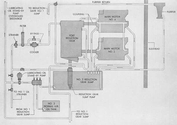
13B1. Description. Lubricating oil for the
reduction gears and the main motors is contained in two sump tanks located beneath the
reduction gears. Oil is supplied to each reduction
gear unit and its bearings, as well as to the main
motor bearings, by means of a pump attached
to and driven by the reduction gears. The attached pump takes its suction directly from its
sump tank and discharges oil directly into the
reduction gear through a check valve, a
strainer, a filter, and a cooler. The pump discharge line is also connected to the discharge
side of the lubricating oil standby pump.
The standby pump is placed in operation
in the event of failure of one of the attached
pumps, and when the propeller shaft speed is
below 34 rpm. The standby system is also used
to prime the main motor and reduction gear
bearings after a shutdown period.
The piping on the gear unit is arranged so
that the oil flow divides, part of it going to the
after bearings and inboard pinion spray box, and
the remainder flowing to the forward bearings,
outboard pinion mesh, and the flexible couplings.
All of the gear lubricating oil drains into
the lower casing and is returned to the sump
through a fitting connected to the bottom of the
casing. A sounding rod may be inserted into the
sump tanks for checking the oil level.
A hand pump is provided for sampling the
contents of the sump tanks. Before starting the
machinery, samples should be taken from the
tanks and examined for presence of water and
dirt. When the hand pump brings up water,
the pump should be operated until the water is
removed. The engine should not be started until
all of the water is removed. The hand pump is
fitted with one suction line which takes a suction
from either of the two sump tanks.
When filling the sump tanks from the filling
line, the oil enters the sump tanks through the
filling and transfer line. New oil may be transferred from the normal lubricating oil tank to
the sump tank by means of the standby pump.
Low-pressure alarms are installed in the
supply lines from the reduction gear to the main
motors. The contact maker is set to close an
alarm circuit when the lubricating oil pressure
drops below the minimum pressure required.
The alarm consists of a twin horn and warning
light, both located in the maneuvering room.
13B2. Maintenance. Efficient lubrication of
reduction gears is of the utmost importance. It
is essential that oil at the designated working
pressures and temperature be supplied to the
gears at all times while they are in operation.
The proper grade of lubricating oil must be
used. The oil must be so thin that the film will
be squeezed from between the teeth, with resultant damage that may be beyond repair, nor so
heavy that it will not flow through the restricted
oil passages.
The lubricating system must be kept clean
at all times. Particles of lint or dirt in the system
are likely to clog the oil spray nozzles. The
lubricating oil must be free from all impurities
such as water, dirt, grit, and any particles of
metal that may enter the system. Particular
care must be taken to clean out metal flakes and
fine chippings when new gears are wearing into
a working fit. Magnets are fitted in lubricating
oil strainers for this purpose.
The importance of taking immediate corrective measures when salt water is found in
the reduction gear lubricating oil cannot be
emphasized too strongly. The immediate location and sealing of the leak or removal of its
source are not enough. Steps must also be taken
to remove the contaminated oil from all steel
parts. Several instances have occurred where,
due to deferring this treatment, gears, journals,
and couplings were so badly rusted and pitted
that the gears had to be taken out by naval
shipyard forces for reconditioning of teeth and
journals. This condition can be reached in a
week or less and may, result in burned-out
bearings.
Frequent tests should be made to determine whether salt water is present in the oil,
and the reduction gears should be inspected
through the inspection plates for signs of salt
water pitting. The oil level in the bottom of the
gear case must not rise above the proper height
predetermined for the particular installation. If
the oil level is too high, the rotation of the gears
will churn and aerate the oil, causing a sudden
265
Figure 13-3. Schematic diagram of port main motor and reduction gear lubricating oil system.
266
increase in its temperature.
Spray nozzles to gears should be kept open
at all times. No oil spray apparatus fitted for the
lubrication of gears should be altered or
rendered inoperative without authority from the
Bureau of Ships.
C. PROPELLER SHAFT THRUST AND ADJUSTMENT
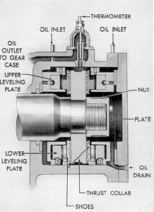
13C1. Description and operation. The
thrust bearing on the forward end of the lowspeed gear shaft is manufactured by the Kingsbury Machine Works. This thrust bearing
restricts axial movement of the propeller shaft
in both the ahead and astern directions. The
principal components of the bearing are a rotating thrust collar, which is keyed to the gear
shaft, and stationary shoes with their load-equalizing supports or leveling plates. Hardened
steel pivots or rocking levers in the back of each
shoe contact the leveling plates and allow slight
titling to equalize the load.
The shoes are the bearing members in this
type of bearing. They are supported in a manner
that permits them to tilt and form a wedge
shaped oil film between the shoe surface and the
collar. The total end play permitted by the
bearing is determined by the thickness of a
spacer which rests against the end cover. This
end play is fixed by the manufacturer at 0.015
to 0.030 inch.
The reduction gear oil pump supplies oil
under pressure at a rate of approximately 3
gallons per minute. This quantity should be sufficient to limit the normal temperature rise
between the oil inlet and outlet to about 15 degrees F.
The oil pressure required is comparatively low,
because the passages within the bearing are
large. There are two oil inlets, one at each end
of the bearing, and a single outlet as shown in
Figure 13-4.
The line admitting oil to the bearing contains a needle valve that may be operated to
obtain the desired flow. With the valve closed,
sufficient oil will be delivered through a drilled
hole in the valve seat for ordinary running conditions.
13C2. Maintenance. During normal operation, the thrust bearing will require no attention
Figure 13-4. Cross section of reduction gear
thrust bearing.
except to see that the necessary circulation of
clean, cool oil is maintained.
Since the bearing surfaces, when running,
are completely separated by oil, there is practically no wear, and therefore, no take-up is provided except by shimming.
During the general overhaul period, the
thrust bearings should be disassembled and
thoroughly cleaned. Cleaning cloths that deposit
lint should not be used. A coarse stone, a scraper,
or a file should not be used on the collar surfaces.
267
D. PROPELLERS
13D1. General. Propellers used on modern
submarines are of the four-blade solid construction type. There are two propellers on each ship,
referred to as the starboard screw and the port
screw. A knowledge of the design of the propeller is not important from the viewpoint of submarine operating personnel. It is enough to say
that the designer has adequately designed the
propeller to give optimum operating characteristics under all conditions of submarine operation, both surface and submerged. It is necessary, however, that submarine personnel have a
knowledge of the terms used in describing a
propeller so as to be able to discuss the subject
of propeller operation more intelligibly. More
important still, they should have some knowledge of the upkeep and maintenance of propellers, so as to keep them in the best possible
operating condition.
13D2. Nomenclature. Terms used in describing a propeller and relative to propeller
operation are as follows:
The pressure face is the after face of the
propeller blade. It is customary to design the
blade section by using this face for datum line.
This is the driving side of the blade which
pushes the water astern when the propeller is in
action.
The suction face is the forward face of the
blade. As this face is under a relatively low pressure, small irregularities in the surface will cause
cavitation. It is therefore important that this
surface be maintained fair and smooth.
Diameter of a propeller is twice the distance from the shaft center to the extreme blade
trip.
Pitch is defined as the distance the blade
element would move in one revolution of operating in a solid medium. Unless otherwise defined,
it is the designed pitch and equals the pressure
face pitch of the blade section at the .7 radius.
When the leading or trailing edge of the pressure face is not a true helix, the design pitch is
considered to be the pitch of that part of the
section which is a true helix.
Projected area is the area of the projection
of the propeller blades upon a plane normal to
the shaft axis.
Disk area is the area of a circle whose
diameter is equal to the propeller diameter.
PA/DA represents the ratio of the projected area to the disk area.
Developed area. The helicoidal (curved)
surface of a propeller blade can be represented
only approximately by a plane area. The developed area therefore approximates the sum of the
actual areas of the pressure faces of all of the
blades. Note: For convenience all areas are
measured from the maximum hub diameter.
This introduces a slight error due to the fact
that the hub is not cylindrical.
Mean width ratio (MWR) is the ratio of
the average width of the developed blade to the
diameter of the propeller.
Pitch ratio is equal to the pitch divided by
the diameter of the propeller.
Cavitation. When a propeller turns at high
speed, the resulting high velocity between the
propeller surface and the water, augmented by
surface irregularities, tends to form a vacuum
adjacent to the propeller. When the absolute
pressure is reduced below the vapor pressure of
the fluid, vapor pockets are formed, which
break the continuity of flow and reduce the efficiency of the propeller. This phenomenon is
called cavitation. When the cavitation bubbles
collapse on the blade surfaces due to condensation, erosion of these surfaces results.
True slip, or slip ratio, is equal to unity
minus the ratio-of the speed of the water relative
to the propeller in feet per minute divided by
the pitch in feet times the rpm. When the speed
of the ship through the water is used instead of
the speed of the water relative to the propeller,
the resulting slip ratio is known as apparent slip.
The difference between these two velocities is
due to the wake created by the ship's hull.
S = I- Va / (rpm X pitch) where
Va = Velocity of water relative to the
propeller in feet per minute.
Propeller numbering. Every propeller has
been assigned a serial number for identification
and to enable the Bureau of Ships to maintain
a complete history. When referring to propellers,
268
the serial number, drawing number, and the
nomenclature appearing on the drawing should
be used.
13D3. Propeller inspection and maintenance.
a. Inspection. Whenever the vessel is in drydock,
the propeller should be inspected for possible
damage. If there is reason to suspect that the
propeller blades have been sprung or bent, and
the fact is not obvious from a visual inspection,
the pitch should be checked with a pitchometer.
Whenever the propeller is removed, the tail
shaft and hub bore should be inspected for corrosion and fractures.
Propellers are dynamically balanced to prevent vibrations. If an inspection and test show
the need of removal of metal to obtain a balance,
the metal must be taken from the pressure
(after) face of the blades.
If an inspection shows small pieces broken
off the blades or slight cracks, repair may be
possible by the hot melt process. If the breaks
or cracks appear to be so serious that either
blade or hub strength is affected, expert consultants should be called in to survey the damage
before any attempt is made to repair. If there
is any question as to the suitability of the damaged propeller, it should be replaced. Pitting or
erosion found during inspection should be considered from the viewpoint of cause and the
elimination of the cause if possible. Fast runs or
steady runs under high power in prolonged
heavy weather will sometimes erode the backs
of the blades. This erosion is due to cavitation
and usually appears at the tips of the blades.
Erosion under these conditions cannot be prevented, but pitting or erosion at any other point
on the blades is usually the result of a fault that
can be eliminated.
b. Propeller blade maintenance. The casting and machining of the propellers require extreme care to maintain the relationship between
the engineering calculations of proper pitch,
diameter, and area and the actual physical
dimensions of the propeller.
Navy propellers are invariably made of
cast solid manganese bronze. Usually small
propellers and frequently large propellers (up
to destroyer size) are machined to their true
pitch. The tolerance allowed is from 1/2 to 2
percent, the amount depending on the application.
All large, and sometimes small, propellers are brought to their final shape by
chipping and grinding.
Propeller blade surfaces must be fair and
free from humps and hollows. Many different
blade thicknesses are used at numerous places
on the blade and each must be accurate to less
than 2 percent. Inaccuracies will set up forces
that cause vibrations resulting in excess noise
which is not acceptable on submarine installations.
Bent blades cause hydrodynamic irregularities which will cause vibrations and sometimes
severe damage to struts and bearings.
Blade fillets located near the hub should
be fair and should change uniformly, decreasing
near the ends. There should never be any
knuckles or sharp corners for the water flow to
break over. Irregular contours always result in
erosion.
Blade edges and tips must be maintained
as sharp and clean as called for on the propeller
drawing. A propeller can vibrate in many different ways, and each vibration is associated with
a definite frequency. Forces that cause vibrations of a definite frequency are sometimes the
result of blunt edges on the blades near the tip,
and these vibrations result in a noisy or singing
propeller. Propellers are dynamically balanced
to prevent vibrations when in service.
Hub taper. The hub of the propeller is
accurately bored out to receive the propeller
shaft. One or more keys are used to insure a
tight fit and to prevent movement between the
shaft and the hub. These keys must fit uniformly and snugly in both shaft and hub, and no
movement should be permitted. Loose keys
work back and forth and may eventually result
in the loss of a propeller.
Fairwater cap. The after end of the
propeller tail shaft is sealed against water by a
fairwater cap which is filled with hot tallow.
Some ships have a separate nut behind the
fairwater cap for holding the propeller hub on
the tail shaft, and some fairwater caps have the
nut integral with the cap. In either case, the cap
and nut must be fitted so that there is no play.
The nut is kept from working loose by a locking
key. The faces of the cap must be smooth and
free of sharp corners or irregularities.
269
13D4. Propeller upkeep. It has been found
that clean and properly operating propellers add
measurably to the amount of speed obtainable
from a given propulsion installation. It has therefore become the practice to clean the blades of
both propellers and perform minor repair jobs
on the blade tips at every refit and overhaul
period of a submarine. It is much easier to do
this when the vessel is in drydock, but the
cleaning especially and some repair jobs may be
accomplished by a diver when the ship is waterborne. The cleaning is usually done by an air operated cleaning tool with little or no difficulty.
When the blades are cleaned, the diver should,
in addition, make a careful inspection of the tips
of the blades to check for irregularities, nicks,
and bent sections. These should be corrected if
the operations schedule permits.
13D5. Routine tests and reports. a. Whenever a ship is-docked the engineer officer (of the
ship) should examine the propellers, and the
result of the examination entered in the engineering log and in the ship's log.
b. As soon as practicable after docking a
vessel, the naval shipyard or repair force should
make a careful examination of the propellers,
and any repairs found necessary should be undertaken immediately so that the undocking of
the vessel will not be delayed.
c. The stenciled hub and blade data should
be verified and recorded at each drydocking.
Wear of bearings, adjustments made, general
conditions found, and work performed should
be recorded in the machinery history.
d. At each interim and regular naval shipyard overhaul docking, the hub cap should be
removed from each propeller and the propeller
nut examined.
e. When repairs are made to propellers, the
activity performing the work should make a detailed report, including repairs effected, condition of propeller, location and extent of defects,
data stamped on hubs and blades, and pitch
measurements, if taken. Applicable forms should
be submitted if major repairs affecting pitch
and blade dimensions have been accomplished
or if the propeller was balanced dynamically.