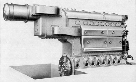
12A1. General. The General Motors 8-268
or 8-268A engine is used on board modern
submarines as an auxiliary engine. It is located
in the lower flats of the after engine rooms, and
may be used for directly charging the batteries
or carrying the auxiliary load, and indirectly
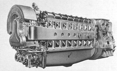
for ship propulsion. The GM 8-268 is an 8-cylinder, in-line, 2-cycle, air started engine rated
at 300 kw generator output at 1200 rpm. In general, the individual parts of the engine are similar to, but smaller than the corresponding parts
in the GM 16-278A. For example, the camshafts, exhaust valve and rocker lever assemblies, injectors, pistons, cylinders, liners and
connecting rods are almost miniature replicas
of the 16-278A parts. The main differences between the engines appear in the construction
and design of the various systems such as the
scavenging air, exhaust, lubricating oil, and
fuel oil systems, as well as in the fact that the
8-268 is an in-line engine.
12A2. Engine stationary and moving parts.
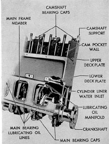
a. Cylinder block. The cylinder block is the
main structural part of the engine. It is composed of forgings and steel plates welded together, combining strength with light weight.
The upper and lower decks of the cylinder
block are bored to receive the cylinder liners.
The space between the decks is the scavenging
air chamber. The bore in the lower deck is constructed with a groove which serves as a cooling
water inlet for the liner. The cylinder liners are
located in the cylinder block by means of dowel
pins in the upper deck.
The camshaft bearing lower support is an
integral part of the cylinder block located at the
extreme top of the block. The bearing cape and
bearing supports are match-marked and must
be kept together.
The forged transverse members in the bottom of the cylinder block form the main crankshaft upper bearing seats. Again the bearing
caps and bearing supports are match-marked
and must be kept together.
Fifteen removable handhole covers permit
access to the crankcase. Eight are located on
one side and seven on the other. The remaining
handhole is covered by the air maze which may
be moved. Seven of the covers are of the safety
type, each having four spring-loaded plates,
which in an emergency, relieve any undue pressure in the crankcase.
The main bearings are lubricated from the
lubricating oil manifold located in the crankcase.
b. Crankshaft. The crankshaft is a heat-treated steel forging finished all over, having
eight connecting rod throws or crankpins 45
degrees apart. The crankshaft is held in the cylinder block by nine main bearing caps. The
bearing at the drive end of the engine acts as a
combination main and thrust bearing. Lubricating oil is supplied under pressure from a
main manifold located in the crankcase, and is
forced through tubes to the crankcase crossframes, where it flows through oil passages to
the main bearings. From the main bearings the
oil flows through drilled holes, in the crankshaft
to the adjoining crankpin and lubricates the
connecting rod bearing. The combination main
and thrust bearing journal No. 9 is not connected by drilled holes to a crankpin. There is
a 1/4-in. diameter radial oil hole in the surface
of this journal into which a capscrew, with the
head ground off enough to clear the bearing
seat, may be inserted for rolling out the upper
shell.
c. Elastic coupling. The power from the
engine crankshaft is transmitted through spring
packs from the inner spring holder of the elastic
coupling, or flywheel, to the outer spring holder,
and from there through the driving disk to the
generator armature shaft flange. A pilot on the
end of the crankshaft fits into a ball bearing in
the armature shaft. The turning gear pinion engages a ring gear shrunk on the rim of the outer
spring holder.
The inner cover of the elastic coupling,
through which the camshaft gear train is driven,
is fastened to the outer spring holder. A helical
230
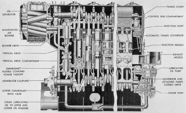
Figure 12-1. Blower end control side of GM 8-268 auxiliary engine.
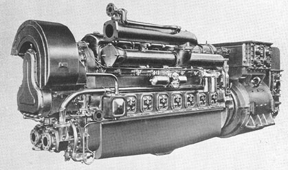
Figure 12-2. Blower end exhaust header side of GM 8-268 auxiliary engine.
231
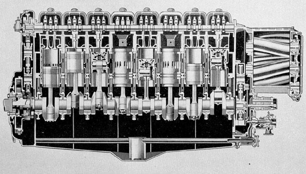
Figure 12-3. Longitudinal cross section of GM 8-268 auxiliary engine.
232
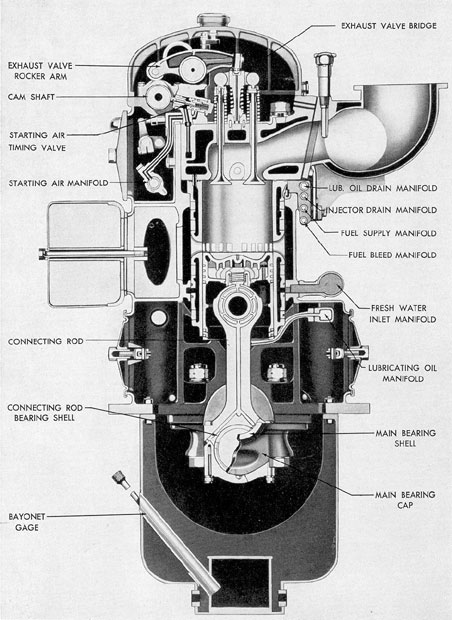
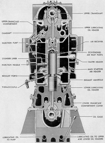
Figure 12-4. Transverse cross section of GM 8-268 auxiliary engine.
233
Figure 12-5. Cutaway of frame, GM 8-268.
internal gear, cut in the inner bore of the elastic
coupling cover, meshes with the crankshaft gear,
forming a splined drive connection to the crankshaft gear which has a loose mounting on the
crankshaft.
The bearing bore of the crankshaft gear.
hub receives oil that flows from the adjacent
main bearing through passages in the crankshaft. The parts of the elastic coupling are lubricated with the oil that flows from the bearing bore of the crankshaft gear hub.
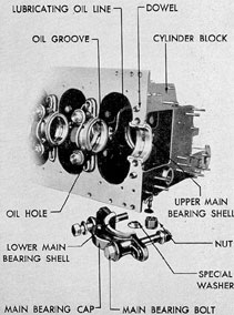
d. Main bearings. Each main bearing consists of an upper and a lower double-flanged,
bronze-backed, precision bearing shell. The
centrifugally cast lining is a high lead bearing
metal called Satco which contains a special
hardener.
The lower shell is mounted in the bearing
cap and the upper shell in its seat in the cylinder block crossframe. The joint faces of the
upper and lower bearing shells project a very
small amount above the seat and cap. That is to
insure that the backs of the shells will be forced
Figure 12-6. Lubrication of main bearings, GM 8-268
into full contact when the cap is fully tightened.
A drilled hole in the lower shell fits on a dowel
pin in the cap. The dowel pin locates the lower
shell in the bearing cap and prevents both the
upper and lower shells from rotating.
Each bearing shell is marked on the edge
of one flange. For example, 2-L-B.E. indicates
that the shell so marked is for the No. 2 main
bearing, the lower bearing shell, and the flange
so marked must be toward the blower end of the
engine. The main bearing nearest the blower
end of the engine is the No. 1 main bearing.
Upper and lower bearing shells are not interchangeable.
Crankshaft thrust loads are taken by the
rear main bearing. The thrust bearing shells are
the same as the other main bearing shells except
that the bearing metal is extended to cover the
flanges. Each main bearing cap is marked with
its bearing number and is marked Blower End
on the side that should face the blower end of
the engine.
Lubricating oil enters the oil groove in the
upper shell through a hole in the top and then
234
flows to the lower shell. The bearing surface of
the lower shell has an oil groove starting from
the joint face at each side and extending partially around the inner surface of the shell.
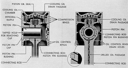
e. Pistons. The pistons are made of an
alloy cast iron. The bored holes in the piston
pin hubs are fitted with bronze bushings. The
outer ends of the bore for the full-floating alloy
steel piston pin are sealed with cast iron caps.
A cooling-oil chamber is formed by an integral baffle, and the piston crown lubricating
oil under pressure flows from the top of the connecting rod, through a sealing member, into the
cooling chamber. The oil seal is a spring-loaded
shoe which rides on the cylindrical top of the
connecting rod. The heated oil overflows
through two drain passages.
Each piston is fitted with six cast iron
rings, four compression rings above the piston
pin and two oil control rings below. These rings
are of the conventional one-piece, cut-joint type.
f. Connecting rods. The connecting rod is
an alloy steel forging. The connecting rod bearing in the lower end of the connecting rod consists
of upper and lower bearing shells. The
bearing shells are lined with Satco metal and
are of the precision type. Each connecting rod
bearing shell is marked on the edge of one
flange. For instance, 1-L-B.E. indicates the shell
is marked for the No. 1 connecting rod, and
lower bearing shell, and the bearing flange so
marked must be toward the blower end of the
engine. No shims are used between the connecting rod and the bearing cap. The upper and
lower bearing shells are not interchangeable.
The lower shell is mounted in the bearing
cap and the upper shell in its seat in the connecting rod. The joint faces of the upper and
lower bearing shells project a very small
amount above the seat and cap. This is to insure that the backs of the shells will be forced
into full contact when the cap is fully tightened.
A drilled hole in the lower shell fits on a dowel
pin in the cap. The dowel pin locates the lower
shell in the bearing cap and prevents both the
upper and lower shells from rotating.
The piston pin is of the full floating type.
The piston pin bronze bushing is a shrink fit in
Figure 12-7. Cross section of piston, GM 8-268.
235
the upper hub of the connecting rod. The ends
of the pin oscillate in the bronze piston pin
bushing hubs of the piston.
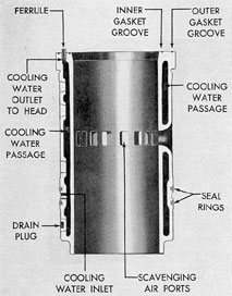
g. Cylinder liner. The cylinder liner is a
cylindrical alloy iron casting with cored annular spaces between the inner and outer surfaces between the inner and outer surfaces
through which cooling water is circulated. The
liner is accurately bored to a smooth finish.
The cylinder liner is held in the engine
block by the lower deckplate and a recess in
the upper deckplate. The cylinder head forces
the liner against the cylinder block. The lower
deckplate has a groove that serves as the water
inlet into the passages in the cylinder liner. It
is made watertight by two synthetic rubber ring
gaskets, called seal rings. The cooling water
flows up through the cylinder liner and into the
cylinder head through ferrules made watertight
by synthetic rubber gaskets. The air intake
ports, through which scavenging air from the
blower enters to supply the cylinder with fresh
clean air, are located around the circumference
of the liner. When the piston reaches the bottom
of its stroke, these ports are completely open
and the air space above the piston is charged
with fresh air.
The joint between the cylinder liner and
the cylinder head is made gastight by an inner
bronze gasket while an outer copper gasket
which has notches in it serves to seat the head
squarely against the cylinder liner.
The drain plug in the lower part of the
jacket of the cylinder liner should be removed
for draining water when freezing temperatures
are expected and an anti-freeze solution is not
in use.
h. Cylinder heads. The engine cylinders
are fitted with individual cylinder heads which
are made of alloy cast iron. Studs in the cylinder block hold each head against the cylinder
liner flange. The joint between the head and
the liner is made gastight with an inner bronze
and an outer copper gasket. The outer gasket
serves to seat the head squarely on the liner.
The shallow milled grooves show leakage of
exhaust gas or water.
The head is also fastened to the vertical
wall of the cam pocket with tap-bolts. The joint
is made oiltight with a synthetic rubber gasket.
Cooling water flows from the cylinder liner into
the head and then flows into the water jacket
of the exhaust manifold.
Each cylinder head is fitted with four exhaust valves, the unit injector, rocker lever assemblies, air starter distributor valve, an over
speed injector lock, the air starter check valve,
and the cylinder test and safety valves.
i. Rocker lever assembly. Each cylinder
head is equipped with three rocker levers, two
of which operate the two pairs of exhaust
valves, and the third operates the injector. The
rocker levers are made of alloy steel forgings.
Bushings are pressed into the lever hubs and
are reamed for a bearing fit on the rocker lever
shaft.
The three rocker levers rock on a fixed
shaft which is clamped in a bearing support.
They are fitted with cam rollers, which operate
in contact with the exhaust and injector cams.
Each of the three cam rollers turns on a bushing
and the bushing turns on a sleeve that has a
loose mounting on the roller pin. Each of the exhaust valve rocker levers operates two valves
236
through a bridge. Each of the valve rocker
levers is fitted at the valve end with a nutlocked adjusting screw, which has a hardened
ball end that fits into the ball socket in the valve
bridge. The injector rocker lever is fitted at the
injector end with a nut-locked adjusting screw,
which has a hardened ball at the lower end.
This ball is fitted with a hardened steel flexibly
mounted shoe. The shoe bears on the injector
plunger follower and transmits the rocker lever
motion to the injector plunger.
The rocker lever shaft is made of alloy
steel and is ground to size. The shaft is clamped
in the bearing support by two bearing caps and
is held in its correct location by a dowel pin in
one of the bearings. A rocker shaft thrust plate
is bolted to each end of the shaft, and a plant
fiber gasket is placed in the joint between the
thrust plate and the rocker lever shaft. The
bearing support is fastened to the cylinder head
with two studs and positioned by two dowels,
and is also held against the head by two of the
cylinder head hold-down studs.
The rocker lever assembly is lubricated
with oil received from one of the camshaft bearings. The oil flows from the top of the camshaft
bearing through a tube to the plate connection
that is fastened to one end of the rocker lever
shaft. From this connection, the oil flows through
drilled passages in the rocker lever shaft to the
three bearings in the rocker lever hubs.
A drilled passage in each of the rocker
lever forgings conducts the lubricating oil from
a hole in the hub bushing to the camshaft end
of the lever. The rocker lever motion permits
oil to flow intermittently under pressure from
the hole in the shaft, through one hole in the
bushing and rocker lever to the cam roller. The
bearing in each of the cam rollers receives oil
through drilled holes in the roller pin and in the
bearing bushings.
j. Camshaft drive. In 2-cycle engine operation the camshaft rotates at the same speed as
the crankshaft. The camshaft drive gears are
located at the power takeoff end of the engine.
They transmit the rotation of the crankshaft to
the camshaft. It is necessary to maintain a fixed
relationship between the rotation of the crankshaft and the rotation of the camshaft so that
the sequence of events essential to the operation
of the engine will be in the proper order.
The forged steel crankshaft gear, which is
driven by, the crankshaft through the elastic
coupling, is keyed on a split collar and drives
the camshaft gear through the crankshaft and
camshaft idler gears. A spacer ring is doweled
to the crankshaft gear.
Steel-backed babbitt-lined bearing shells
support the inner and outer hubs of the forged
steel helical idler gears. The inner and outer
supports are bolted and doweled together before
being mounted in the camshaft drive housing.
The fuel oil pump and governor are driven
from a gear that meshes with the lower idler
gear. A pair of bevel gears drives the vertical
governor shaft which is mounted in ball
bearings.
The lower idler gear also drives the quill
shaft gear, which is splined for the quill shaft
that drives the blower and accessory gear trains.
A splined coupling, which rotates in the babbitt-lined center bearing, joins the two sections of
the quill shaft.
The overspeed trip weight assembly and
the camshaft gear are bolted and doweled to a
hub that also serves as a bearing journal for this
assembly. The hub is splined to fit on the end
of the camshaft.
Lubricating oil for the camshaft drive gear
train and bearings is piped from the end of the
lubricating oil manifold in the cylinder block.
Oil is supplied under pressure to the hollow
camshaft through the camshaft gear bearing.
Open jets spray oil on the gear teeth.
Complete dynamic balance of the engine is
obtained by balance weights mounted in a certain relation to each other on the gears in the
front and rear gear trains.
k. Accessory drive. The accessory drive,
located between the end of the crankcase and
the blower, consists of a train of helical gears
driven from the camshaft drive gear train
through the quill shaft. The gears in the accessory drive are match-marked with a definite
relationship to the match-marks on the gears in
the camshaft drive gear train, to maintain the
237
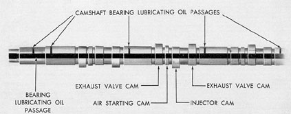
Figure 12-9. Cross section of camshaft, GM 8-268.
relationship between the balance weights in
both trains.
The accessory drive gear drives the upper
idler gear. This upper idler gear drives the lower
idler gear. A plate with a splined hub for driving
the lubricating oil pump is bolted to the hub of
the lower idler gear. The fresh water and sea water pump drive gears are driven from the lower
idler gear. The hubs of the water pump drive
gears have a spline cut in the bore for the fresh
water and sea water pump shafts. The hubs
which project from each side of the lower idler
and water pump gears run in steel-backed babbitt-lined bearings mounted in the inner and
outer bearing supports. These bearing supports
are bolted together and the assembly is fastened
in place on the inside of the accessory drive
housing.
Lubricating oil is piped to the accessory
drive from the main lubricating oil manifold in
the cylinder block. Oil lines and connecting pass
ages in the bearing supports supply oil to the
bearings in the drive.
The accessory drive cover should be removed periodically and the gear train inspected
for excessive wear of any parts. Lubricating oil
lines and passages should be checked periodically to insure that they are not broken or
clogged. All nuts and capscrews should be tight.
1. Camshaft. The camshaft is of the one-piece type with integral case-hardened cams
and bearings. The bearing bushings, which are
steel backed and babbitt lined, are held on their
seats in the cam pocket with bearing caps.
There are four cams for each cylinder. The
two outer cams operate the exhaust valves, and
the center cam operates the injector. The fourth
cam, which is narrower than the other three,
operates the air timing valve.
The camshaft drive end of the camshaft is
splined for a driving connection in the hub of
the camshaft gear which is driven from the
crankshaft gear through a train of idler gears.
Lubricating oil under pressure is supplied
to the camshaft bore through the splined drive
connection. The oil is then delivered to the
camshaft bearings through radial holes in the
camshaft. Oil for lubricating the rocker lever
mechanisms flows through tubes from the camshaft bearing caps.
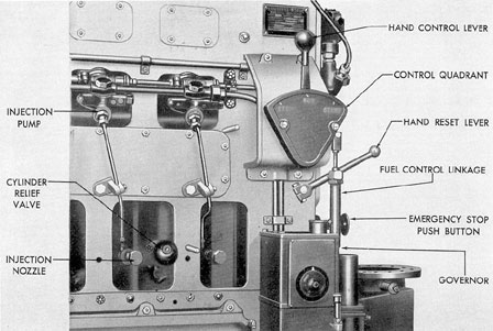
m. Engine control. The governor, which is
located at the generator end of the engine, controls the engine speed for any setting.
The movement of the governor power
mechanism is transmitted through lever and
link connections to the injector control shaft in
the cam pocket. Each fuel injector rack is connected to a control shaft lever through a slipjoint link. A micrometer adjusting screw on this
link increases or decreases the amount of fuel
injected into the combustion chamber.
A slip joint is connected to each injector
rack so that in case the control rack in one injector binds, the compression of the spring in
238
the slip-joint link allows normal operation of
the other injectors. Each spring is preloaded to
limit the force that can be applied by the governor to move the injector control racks. When
the link is either shortened or lengthened by a
load greater than its assembly load, the spring
is compressed.
The start and stop lever is used for
manual control when starting or stopping the
engine, and its movements are transmitted
through a connection that provides for unrestricted governor control when the start and
stop lever is latched in the RUN position. The
governor connections to the injector control
shaft include an extensible spring-loaded link
which permits the injector control shaft to be
turned manually without moving the governor
power piston.
When the governor or any part of the injector control system is renewed, the governor
power piston should be linked in the correct
relation to the injector rack.
n. Overspeed trip. The overspeed trip
mechanism stops the injection of fuel oil to the
combustion chambers when the engine speed
exceeds 112 percent of rated speed.
The overspeed trip weight assembly,
mounted on the camshaft gear, is fitted with a
spring-loaded flyweight. The spring tension is
adjusted so that, at a predetermined engine
overspeed, the centrifugal force moves the flyweight radially until it strikes a roller latch, releasing the spring-actuated injector lock shaft
in the cam pocket at each engine cylinder. The
injector lock carries a lever on the shaft that
moves a pawl engaging a notch on the injector
rocker lever. The injection of fuel stops when
the locked rocker lever holds the injector
plunger at the lower end of its pumping stroke.
The overspeed trip is manually reset with
a hand lever on the shaft which projects from
the camshaft drive housing.
12A3. Fuel oil system. a. Description. The
fuel oil pump draws oil from the clean fuel oil
tank and forces it through the fuel block and the
fuel oil strainer and filter. From the filter, the
oil flows to the fuel supply manifold, which is
the third pipe from the top in the multiple oil
pipe assembly, and then through a small jet
filter on the cylinder head to a jumper tube
that supplies the injector. The injector inlet
contains another filter to further prevent solid
matter from reaching the spray valve.
The surplus fuel is bypassed in the injector
and flows through another filter in the injector
outlet passage so that any reverse flow of fuel
cannot carry dirt into the injector. The surplus
fuel passes from the injector through a tube to
a fuel bleed manifold, which is the bottom pipe
in the multiple oil pipe assembly. The fuel from
this bleed manifold flows to the metering block,
through the metering valve which sets up
enough resistance to maintain the required pressure in the fuel supply manifold, and then flows
back to the clean fuel oil tank.
Fuel oil leakage from the injector plunger
and bushing is drained through an injector body
ferrule, through a cylinder head passage into
a manifold connection clamped between the
cylinder block and cylinder head. The injector
drainage is conducted through this connection
to the second manifold from the top in the
multiple oil pipe assembly and then it flows
through the drain to the fuel oil tank or bilge.
b. The unit injector. On this engine, the
fuel pump and spray valve are combined into a
single and compact unit called a unit injector,
which meters the fuel and also atomizes and
sprays it into the cylinder. This injector is similar to that used in the GM 16-278A and its
operating principle is identical. The unit injector is held in position in a water-cooled jacket
in the center of the cylinder head: At the lower
end, the injector forms a gastight seal with the
tapered seat in the cylinder head. All the injectors in this engine are alike and interchangeable. Fuel is supplied through jumper tubes
with spherical type gasketless connections.
The pumping function of the injector is
accomplished by the reciprocating motion of
the constant stroke injector plunger which is
actuated by the injector cam on the engine
camshaft, through the injector rocker lever.
The position of the plunger, and thereby
the timing, is adjusted by means of the ball
stud and lock nut at the injector end of the
rocker lever.
The quantity of fuel injected into each
cylinder, and therefore the power developed in
239
that cylinder, is varied by rotating the plunger
by means of the injector control rack. A rack
adjustment (called the microadjustment) located on the control linkage permits balancing
the load of each cylinder while the engine is
running,
c. Fuel block. The fuel block is located
under the exhaust manifold at the camshaft
drive end of the engine and in front of the fuel
oil pump. The fuel block contains a metering
valve, a priming valve, and an adjustable pressure relief valve.
d. Jet filters. The cylinder head jet filters
are located on each head, just above the exhaust
manifold connection. The element in each cylinder head is of the edgewise-wound metal ribbon type. This filter is correctly assembled
when the helical spring and cap are placed over
the long end of the filtering element to hold the
element flange against the shoulder at the inner
end of the filter wall.
e. Fuel pump. The fuel oil pump is located
under the exhaust manifold at the camshaft
drive end of the engine and is of the positive
displacement, spur gear, rotor type. Fuel enters
the pump through the top port in the end of
the pump and is discharged from the lower port
on the side of the pump. Each pump gear is
keyed to its shaft by a pin.
f. Fuel oil strainer. The fuel oil strainer
contains two straining units, each with an inner
and outer winding. The space between the windings on the inner and outer elements is 0.001 in.
Fuel oil enters the strainer case, flows
through the outer and inner windings, through
the center of the elements, and out through the
strainer head.
Provision is made for using either one or
both strainer units. When the handle on the unit
is shifted to the No. 1 position, the oil is flowing through the No. 1 unit. This applies also to
the No. 2 position. When the control valve is
in the Both position, oil is flowing through both
units. This is the position of the control valve
for normal operation. The positions of the control valve and the number of the corresponding
straining unit are cast into the strainer head at
the control valve.
g. Fuel oil filter. The fuel oil filter is a
duplex filter with provisions for using either one
Figure 12-10. Cross section of Northern fuel oil
pump used on GM 8-268 engine.
or both filtering units. In normal operation both
filtering units are in operation.
The arrows under the valve handles show
the positions of the valve handles for using
either one or both of the units. The flanges are
also marked IN and OUT indicating the direction of flow of fuel oil through the filter. When
the valve handles are between the two positions
indicated on the valve handle base, or with the
valve handles directly above the inlet and outlet flanges, fuel oil is passing through both
units. If the valve handle on the IN end of the
filter is in one of the positions indicated by the
arrow on the casting, the valve handle on the
OUT end of the filter must be in the corresponding position. The flow of fuel oil to the
engine will be stopped if both valve handles
are not pointing in the same direction when
using only one filtering unit.
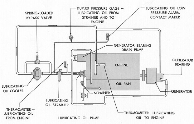
12A4. Lubricating oil system. a. Description. The lubricating oil pressure pump,
mounted directly below the blower, draws hot
oil from the oil pan through a strainer in the
240
pump suction line. A spring-loaded pressure
relief valve is built into the discharge passage
of the pump body, which bypasses excess oil
into the engine oil pan. The pump forces the
oil through the strainer and the cooler into the
engine lubricating oil system. The engine inlet
connection, on the blower and pump drive housing, is fitted with a spring-loaded relief valve.
The spring pressure is adjusted by means of a
regulating screw to maintain the correct pressure. Any surplus oil is returned to the oil pan.
Lubricating oil is supplied to the lubricating oil manifold in the cylinder block. From
this manifold, oil is forced through tubes to the
crankcase crossframes, where it flows through
oil passages to lubricate the main bearings. The
crankpin bearings are lubricated with oil received from an adjacent main bearing through
oil passages in the crankshaft. Oil holes in the
upper connecting rod conduct lubricating oil to
the piston cooling chamber in the top of the
piston.
The camshaft drive gears are lubricated
with oil from the generator end of the lubricating oil supply manifold in the engine block.
Oil is piped from this manifold to the camshaft
drive gear bearing support and to the lubricating oil distribution block in the camshaft
drive housing. Lines from the distribution
block carry oil to the other gear bearings in the
camshaft drive and the mating teeth of the gears
in the camshaft drive. The lubricating oil from
the camshaft drive housing is returned to the
engine oil pan by the camshaft drive housing
scavenging pump.
Oil under pressure is supplied to the camshaft bore through the splined drive connection.
The oil is then delivered to the camshaft
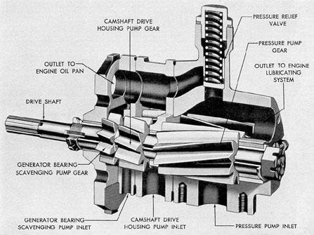
Figure 12-11. Cutaway view of GM 8-268 lubricating oil pump.
bearing through radial holes in the camshaft. Oil for
lubricating the rocker lever mechanism flows
through tubes from the camshaft bearing caps.
This oil also furnishes lubrication for the valve
assembly. The oil then drains to the oil pan.
The blower and accessory drive gear bearings receive oil from the blower end of the lubricating oil pressure manifold in the engine
block. Oil for the blower bearings and gears is
received from the relief valve connection on the
main lubricating oil manifold, and then is conducted through the tubes under the rotor housing to passages in the blower endplates, and
returned to the oil pan.
b. Lubricating oil pump. The attached lubricating oil pump unit is mounted below the
blower. The pump unit is of the positive displacement, helical gear type, and consists of a
lubricating oil pressure pump, a camshaft drive
housing scavenging pump, and a generator bearing scavenging pump. The lubricating oil pressure pump supplies lubricating oil to the engine.
The camshaft drive housing scavenging pump
Figure 12-13. Cutaway of lubricating oil cooler
GM 8-268.
draws the oil from the camshaft drive housing
and returns it to the engine oil pan. The generator bearing scavenging pump draws the excess
oil from the generator bearing and returns it to
the engine oil pan. The pump housing is made
in four separate parts: the bearing flange, the
generator bearing scavenging pump housing, the
camshaft drive housing scavenging pump housing, and the lubricating oil pressure pump housing. The driving gear shaft bearings are located
in the pump housing. The driven gears, fitted
with bronze bushings, rotate on the stationary
idler gear shaft.
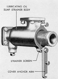
c. Strainers. Two types of strainers are
used in this installation. The lubricating oil suction strainer is located in the pump intake line
at the blower end of the engine and strains the
oil entering the pump from the engine lubricating oil pan. The straining element is made of
wire screen and is in the shape of a cylinder.
The pump draws oil through the open end of
the strainer element and sends it out through
its side.
The other strainer in the system is the supply line strainer which is similar to the strainer
found in GM 16-278A engines. The strainer
case contains a cylindrical straining element of
the edgewise-wound metal ribbon type. A
handle on the top of the unit is used to revolve
the straining element under metal cleaning
blades. The strainer should be cleaned frequently when the engine is running, by turning
the cleaning handle one or more complete revolutions.
The direction in which to rotate the cleaning handle is indicated by an arrow. The pressure drop through the strainer is an indication
of the condition of the straining element.
The other lever on the strainer operates the
bypass valve. When the lever is in the ON position the lubricating oil is flowing through the
strainer. When the lever is in the BYPASS position the oil is flowing directly through the head
of the unit, and the strainer case and element
can be removed and cleaned. The ON and
BYPASS positions are indicated on the strainer
case.
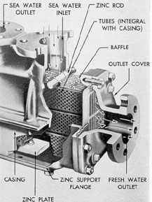
d. Lubricating oil cooler. The lubricating
oil is cooled in a Harrison type cooler that is
made up of a core assembly and an enclosing
case. The oblong tubes enclose a series of baffles
which form a winding passage for the flow of oil.
The tubes are fastened to header plates at the
ends. The core assembly is permanently attached to the casing.
12A5. Cooling system. a. General. The cooling system is of the closed type, employing
fresh water to cool the engine, with salt water
in the generator air coolers and acting as the
cooling agent in the fresh water cooler.
b. Salt water system. The salt water pump
draws water from the sea chest through a
strainer and forces it through the engine water
cooler and out through the overboard discharge.
The pump also forces sea water through a
branch line to the generator coolers. The valve
controlling the flow of salt water through the
generator coolers should be set to keep the temperature of air in the generator at the temperature specified in the manufacturer's instruction
book.
c. Fresh water system. The fresh water
pump forces the water into the engine water
manifold and into the cylinder liners through
the lower deckplate in the engine block. The
water is then pumped upward to the cylinder
heads through the ferrules in the top of the liner.
From the cylinder head the cooling water flows
to the water jacket around the exhaust manifold, to the fresh water and lubricating oil
coolers, and back to the pump. The fresh water
system is filled through the expansion tank. Control of the fresh water temperature is by means
of a temperature regulator identical with that
found on 16-278A engines.
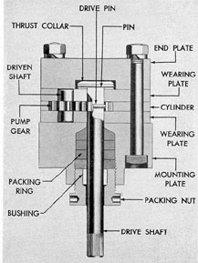
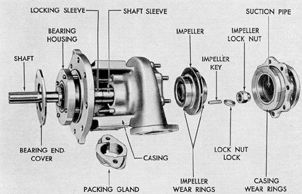
d. Fresh water and salt water pumps. The
fresh water and salt water pumps are of the,
centrifugal type. Water enters the center of
the impeller and is thrown outward through the
impeller vanes by the rotating motion of the
pump.
The pump impeller is keyed to the tapered
end of the driving shaft and rotates in the pump
housing on two pairs of replaceable bronze wear
rings.
A packing sleeve is keyed to the shaft and
butts against the impeller. A watertight seal is
provided by three 1/8-in. square plastic metallic
packing rings that fit in a recess of the packing
sleeve. This packing is tightened by rotating the
locking sleeve with a spanner wrench, thereby
compressing the packing. The sleeve is locked
in place with a setscrew. The packing gland
must be removed and the setscrews loosened
before the locking sleeve can be tightened.
A finger, locked to the shift with a setscrew, throws off any water that may work its
way along the shaft toward the ball bearing. The
ball bearing is pressed on the shaft and can be
removed only with the bearing puller furnished
for this purpose. This bearing is lubricated by
splash from the accessory drive. A leather seal
prevents the oil from leaking out of the bearing
housing.
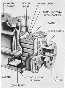
e. Fresh water cooler. The engine water is
cooled in a Harrison type cooler consisting of a
core assembly and an enclosing case. The oblong
tubes are baffled to form winding passages for
the flow of engine water. The tubes are fastened
to header plates at the ends. The core assembly
is permanently attached to the casing.
12A6. Air intake and exhaust systems. a.
General. An air blower scavenges the engine
243
Figure 12-16. GM 8-268 water pump disassembled.
cylinders by forcing air through the intake ports
in the liners as the pistons approach the end of
their power strokes. This air forces out the
burned exhaust gases through the open exhaust
valves in the cylinder head.
Air is drawn by the blower through an
intake silencer and is discharged through a distributor manifold into the air box surrounding
the cylinders. Air is admitted to each cylinder
when the piston uncovers the intake ports.
These ports are designed to produce a swirling
flow of air upward through the cylinder toward
the exhaust valves which open for the discharge
of the exhaust gases. This results in complete
scavenging and filling of the cylinders with
clean air.
The exhaust gases from each cylinder are
discharged into a water-jacketed manifold,
which in turn discharges the gases into one of
the main engine exhaust pipes (usually No.
3ME) and thence to the atmosphere.
The cooling water flows from each cylinder
head into the water passages of the manifold.
From the manifold the water passes through an
elbow into the expansion tank. (See Section
12A5.)
Thermocouples for measuring the temperature of the exhaust gases from each cylinder
are located in the manifold.
b. Blower. The blower consists of a pair of
rotors revolving together in a closely fitted housing. Each rotor has three helical lobes which
produce a continuous and uniform displacement
of air. The rotors do not touch each other or the
surrounding housing. Air enters the housing at
one side and fills the spaces between the rotor
lobes as they roll apart. The air is carried around
the cylindrical sides of the housing, into the
closed spaces between the lobes and the housing,
and is forced under pressure to the discharge
side of the housing as the lobes roll together.
Then the air passes through a distributor manifold into the air box around the cylinder liners.
Each rotor is carried by a tubular serrated
shaft. Endwise movement is prevented by two
taper pins. No gaskets are used between the
244
Figure 12-17. Cutaway of fresh water cooler,
GM 8-268.
endplates and the housing due to the importance of maintaining the correct rotor end
clearance. A fine silk thread around the housing, inside the stud line, together with a very
thin coat of non-hardening gasket compound,
provides an airtight seal.
Large babbitted bearings in the endplates
accurately locate the rotors in the two half-bores
of the housing so that the clearances between
the rotor tips and the housing bores can be held
to a minimum. Both ends of the rotor bearings
at the gear end of the blower are made with
thrust surfaces that locate the rotor endwise and
prevent contact between the rotors and the endplates.
The power to drive the blower is transmitted directly to the rotor gear train by a drive
shaft that extends through a passage in the
blower housing. Closely fitted helical rotor gears
are rigidly attached to both rotor shafts to prevent the rotors from touching each other as they
roll together. Each hub is pressed on the serrated rotor shaft. A
hexagon head lockscrew,
threaded in the rotor shaft, holds a thrust collar
as a spacer between the gear hub and the end
of the rotor, maintaining the clearance between
the rotors and the blower endplate.
The blower rotor gears are bolted to the
gear hub flanges and are located angularly by
hardened dowel pins. Due to the importance of
having the rotors roll together without touching,
yet with the least possible clearance, it is necessary to locate the dowel pins during the assembly for a given set of gears and hubs. This is the
only adjustment provided for timing the gears
with respect to the rotors.
Oil passages in the endplates conduct lubricating oil under pressure to the bearings. Oil
seals are provided at each bearing to prevent
oil from entering the rotor housing.
c. Air maze. A breather system is used to
prevent contamination of the engine room atmosphere by heated, fume-laden air that otherwise would escape from the engine crankcase.
This ventilation of the crankcase also reduces
the formation of sludge in the oil and prevents
the accumulation of combustible gases in the
crankcase and oil pan.
Atmospheric air for the breather system enters the engine through the cylinder head cover
breathers. The blower draws air from the crankcase through the air maze which prevents oil
mist from being drawn into the blower.
The air maze element consists of a number of fine steel and copper wire screens. Oil laden air is drawn through the air maze screens.
The oil deposited on the screens, drains to the
bottom of the air maze housing. This separated
oil is returned to the accessory drive cover
through a drain tube.
12A7. Air starting system. High-pressure
air is piped to a lever-operated air starting valve.
When the lever opens the valve, it allows the air
to flow through the starting air manifold in the
cam pocket of the crankcase to the individual
air distributor valves or air timing valves in the
rocker lever bearing support at each cylinder.
The distributor valve is of the poppet type and
is operated from the narrow earn in each group
of four on the engine camshaft. Starting air from
each distributor or timing valve is conducted
245
through passages in the rocker lever bearing support and cylinder head to the air starter check
valve. The joint between the rocker lever bearing support and the cylinder head is made airtight with a metal ferrule and a neoprene gasket.
The air starter check valve prevents exhaust
gases from entering the air starting passage. It
is opened by the high-pressure starting air and
closed by a spring when the starting air from
the timing valve is cut off. From the check valve
the starting air flows into the space above the
piston and forces the piston downward until the
air distributor valves closes and the exhaust
valves open.
B. FAIRBANKS-MORSE 38E 5 1/4 ENGINE
12B1. General. The F-M 38E 5 1/4 7-Cylinder engine is used as an auxiliary engine on
submarine whose main propulsion engines are
Model 38D 8 1/8 Fairbanks-Morse engines. Like
the GM 8-268 engine, it is located on the lower
deck level of the after engine room and may be
used to carry the auxiliary load, to charge batteries and indirectly for propulsion. The engine
is of the opposed piston type, with 7 cylinders
in line and air started, and is rated at 300 kw
generated output at 1200 rpm. It works on exactly the same principle as the F-M 38D 8 1/8,
and most of the parts are identical in design, the
only difference being in the size and dimension
of the parts.
12B2. Operation. The opposed piston engine
is of the solid injection, inlet and exhaust port,
scavenging blower type and is designed to use a
variety of fuels. The two pistons in each cylinder
work vertically against each other, forming a
single combustion space between the pistons at
the center of the cylinder. The cross sections of
the engine show the relative positions of the
blower, crankshaft, pistons, and generator.
The engine operates on the two-cycle principle in which two strokes of each piston and
one complete revolution of each crankshaft are
necessary to complete the cycle. The cycle begins with the movement of the pistons from
their outer dead centers. As the pistons move
Figure 12-18. Control side of 7-cylinder F-M auxiliary engine.
246
Figure 12-19. Longitudinal cross section of 7-cylinder F-M auxiliary engine.
247
Figure 12-20. Transverse cross section of 7-cylinder F-M auxiliary engine.
248
inward they cover the exhaust and inlet ports
and start to compress the air in the cylinder. As
the pistons approach combustion dead center,
fuel is injected into the combustion space in a
fine spray. The fuel immediately starts to burn
and expansion follows, forcing the pistons outward and delivering work to the crankshafts.
The shafts are connected by a vertical gear
drive.
Toward the end of the expansion stroke,
the lower pistons uncover the exhaust ports and
allow the burned gases to escape to the atmosphere through the exhaust system. Soon afterward, the upper pistons uncover the air inlet
ports. At this point the pressure in the cylinder
is about atmospheric. As the inlet ports are uncovered, the scavenging air under pressure in
the air receiver rushes into the cylinder with a
whirling motion, sweeping the cylinder clear of
any remaining exhaust gas and filling it with
fresh air for the next compression stroke. The
whirling motion or turbulence of the air is obtained by the tangentially cast inlet ports. This
turbulence persists throughout the injection
period and aids in the mixing of the air and fuel.
With this arrangement of the pistons and
crankshafts as described above, the lower crankshaft will lead the upper crankshaft by approximately 12 degrees. The difference in the crankshaft
setting is referred to as the lower crank lead.
The two pistons will be the nearest together
when the upper piston is approximately 6 degrees
ahead of inner dead center and the lower piston
is 6 degrees past inner dead center. The point midway
between the two pistons when they are in this
position is called the piston dead center.
From the foregoing it can be seen that
when the upper piston reaches inner dead center, the lower piston will have completed 12 degrees of
the expansion or power stroke. This causes the
lower piston to receive the greater part of the
expansion force with the result that at full load
about 70 percent of the total load is delivered
by the lower crankshaft. The remaining power
is delivered to the upper crankshaft where it is
partially utilized in driving the scavenging
blower. Any residual power is transmitted
through the vertical drive gear to the lower
crankshaft which is connected to the generator.
Figure 12-20 shows a transverse cross section of
the working cylinder.
12B3. Engine main moving and stationary
parts. a. Cylinder block. The cylinder block
is the main structural part of the engine and is
designed to give it the necessary strength and
rigidity. It is constructed of hot rolled steel
plates of the proper dimensions welded into a
single unit, combining compactness and
strength with lightness of weight.
Transverse vertical members together with
horizontal decks form enclosures, housings, and
fastenings for the operating parts of the engine.
The four horizontal decks are bored to receive
the cylinder liners along the centerline of the
engine. An extension of the block is provided
for attaching the scavenging air blower at the
vertical drive end of the engine.
The cylinder block is separated into the following compartments:
1. The control end compartment which
forms an enclosure for the timing chain, controls,
overspeed and timing governors, and drives for
the regulating governor and attached pumps.
2. The vertical drive compartment which
houses the vertical gear drive that interconnects the upper and lower crankshafts. Used oil
from the drive gears and upper crankcase compartment drains down through this compartment to the oil pan or engine sump.
3. The upper crankcase compartment
which forms the bearing saddles for the upper
crankshaft bearings and bearings hubs for the
camshaft bearings. The saddles and bearing
hubs are drilled for passage of lubricating oil
to the bearings from the upper oil header. The
used oil from these parts collects on the floor of
this compartment and drains way from the
center of the block toward each end where it
passes through openings to the engine sump or
oil pan.
4. The air receiver compartment which
extends the full length of the block and completely surrounds the cylinder liners at the air
intake ports, forming a passage for scavenging
air from the blower to the inlet ports of the
cylinder liners.
5. The injection nozzle compartments
249
which form enclosures for the injection nozzles,
air start check valves, and cylinder relief valves.
The injection pump, which is cam actuated, is
located at an angle in the underside of the upper
crankcase on the control side and furnishes fuel
under pressure to the injection nozzle.
6. The exhaust compartment which extends
the full length of the block on each side. The
exhaust decks are bolted to the block and surround the cylinder liner, forming water-cooled
passages for the exhaust gases from the combustion spaces to the exhaust manifolds. The
manifolds are water-cooled welded steel units,
bolted to the cylinder block and exhaust decks.
7. The lower crankcase compartment
which forms bearing saddles for the lower main
and thrust bearings. These saddles are drilled
for the passage of lubricating oil to the bearings.
The used oil from the engine collects in the oil
pan or engine sump.
After welding, the block is sand blasted
and stress relieved to remove the internal
strains at certain vital points. It is then magnafluxed to check for the presence of any construction faults.
The various compartments are provided
with covers. The upper crankcase compartment
is closed by a top cover bolted to the block. The
cover has several inspection covers along the
top, one of which is an explosion cover to relieve
any excess pressure built up in the upper crankcase. An explosion cover on the control end of
the block above the exhaust nozzle prevents the
possibility of excess pressure building up in the
lower crankcase.
The main and thrust bearing saddles are
machined together with the forged steel bearing
caps. These are match-marked to show proper
position. When a replacement cylinder block is
ordered the bearing caps are always furnished
in place.
b. Cylinders and cylinder liners. The cylinders are formed by cylindrical sleeves or liners
located on the centerline of the engine and
spaced to correspond with the crankshaft throws.
The cast iron liners have specially designed air
inlet and exhaust ports for the passage of scavenging air to, and of exhaust gases from the
combustion space.
The liner cooling spaces are formed by
cylinder liner jackets which are pressed on the
outside of the liners. They extend from the bottom of the scavenging air inlet ports to a short
distance above the exhaust ports.
Openings for the air start check valve,
cylinder relief valve, and injection nozzle are
located in the liner and liner jacket at the point
where the pistons arrive at inner dead center.
The channels directing the cooling water
up and around the cylinder liner are cast in
between the ribs on the liner. The heat of
combustion that accumulates in the cylinders,
as well as the heat conducted to the air start
check valve, cylinder relief valve, and injection
nozzle, is transferred to the cooling water which
flows into these passages through regular fittings
from the water jacket of the exhaust manifold.
The water leaves the cylinder liner near the top
of the jacket by means of an outlet pipe to the
water header.
c. Crankshafts and main bearings. The
crankshaft is a heat-treated, cast iron shaft with
an allover finish. It is held in the cylinder block
by main bearing caps. The bearing at the
blower end of the upper crankshaft and at the
coupling end of the lower crankshaft act as
combination main and thrust bearings.
The crankshaft is drilled from each main
bearing journal to each connecting rod journal
so that oil, furnished to the main bearing saddles
from the oil headers, flows into the crank and
into each connecting rod journal. The combination main and thrust bearings are not connected
to any connecting rod journal; accordingly they
are not drilled, but receive their oil from separate tubes direct from the oil headers.
d. Vertical drive assembly. The power developed by the upper crankshaft is transmitted
to the lower crankshaft by means of a gear
drive which is turned by the crankshaft gear
bolted to the blower end of each crankshaft. The
drive assembly consists of two tapered shafts
with pinions, connected together by a flexible
coupling with laminated rings between the hubs,
coupling shaft, and adjusting flange. The upper
and lower housings contain a large and a small
set of thrust bearings.
e. Connecting rod and connecting rod bearings. The connecting rod is an alloy steel forging
with a closed eye at one end and a removable
250
cap at the other end. The connecting rod crankpin bearing is made up of a cap bearing shell
and a rod bearing shell. The bronze-backed
bearing shells are lined with a high lead bearing
composition containing a special hardener and
known under the trade name of Satco metal.
Each connecting rod crankpin bearing shell is
identified by a mark stamped on the edge of the
shell. New shells may be installed without fitting
or scraping. The piston pin bearing consists of
two rows of hardened steel rollers or a bronze
bushing fitted in the space between the piston
pin and the connecting rod bushing.
f. Piston and piston pin assembly. The
upper and lower cast iron pistons are identical
except for the position of the fuel opening in
the cup at the top of the piston. The pistons are
marked and should be installed in their proper
places, so that the fuel openings line up correctly with the injection nozzle openings in the
liners.
The pistons are connected to their respective crankshafts by the piston pin bracket, piston
pin, needle bearings or bronze bushing, and
forged steel connecting rods, and are cooled by
lubricating oil as described later.
Each piston is fitted with seven cast iron
rings, four of which are compression rings located above the piston pin and three of which
are oil rings located below the piston pin. Of
these three rings there is one oil scraper, one
oil drain, and one oil cutter ring.
The condition of the lower piston and rings
may be observed through the exhaust manifold
and ports after the thermocouple or plain covers
have been removed from the manifold.
g. Camshaft, camshaft stub shaft, and camshaft bearings. The camshaft is of the one-piece
type with integral cams on a case-hardened alloy
steel shaft. There is one cam on the camshaft for
each cylinder. This cam actuates the injection
pump plunger. There is only one camshaft on
this model F-M engine. On the other side of the
engine from the camshaft is a camshaft stub
shaft which is used to drive various governor
auxiliaries and to form a part of the timing
chain system. This stub shaft is extremely short,
extending for the length of one cylinder only.
The camshaft bearings are held in place in
the block by special setscrews. Exceptions to this
are the bearings at the blower end of the camshaft stub shaft, which are held in place by a
bearing nut. Oil is supplied to the control end
bearings by a pipe that leads directly to the
camshaft bearing saddle from the upper oil
header. The oil flows through the hollow shaft
and supplies oil to the rest of the bearings by
means of the radial holes drilled in the shaft.
h. Timing chain. The timing chain is the
means by which the rotation of the upper crankshaft is conveyed to the camshafts, turning the
camshafts at the same rate of speed as the
crankshaft. Sprockets are fastened to the control
end of the crankshaft, camshaft, and stub shaft.
The chain is guided by special links over the
crankshaft sprocket, under a timing chain
sprocket, and over the camshaft sprocket. It
then passes under a tightener sprocket, over the
stub shaft sprocket, and under a second timing
chain sprocket to the crankshaft.
The timing chain is a No. 766 Duplex 1/2 in.
pitch, 2 in. wide, center guide, endless chain of
116 pitches. It is assembled to operate the links,
to guide the chain on the camshaft and crankshaft sprockets, and to operate in slots in the
tightener and timing sprockets.
i. Hand control lever. The engine is started
and stopped by means of a hand-control lever.
This lever has three positions: START, STOP,
and RUN. In the STOP position, the fuel cutout
cam on the control shaft moves the fuel injection pump control rod to the no fuel position.
When the lever is in the START position, the
control shaft mechanism moves the air control
valve plunger and opens the control valve, admitting air to the engine air header and air
distributor. In the RUN position, the engine is
under full governor control.
j. Emergency stop and reset lever. The
engine is equipped with a hand-operated emergency stop device, consisting of a push button
that operates against the overspeed latch and
releases the overspeed stop plunger, shutting off
the delivery of fuel to the injection pumps. This
emergency stop may be connected to the ship's
air supply so that it can be operated from the
maneuvering room by the use of a quick opening
valve to stop the engine. When air pressure is
admitted to the emergency stop housing, the
overspeed stop latch is tripped and shuts off the
251
Figure 12-21. Engine controls, end view, F-M auxiliary engine.
supply of fuel as described in the preceding
paragraph.
k. Overspeed governor. The overspeed governor mechanism automatically stops the engine
when the main governor fails to hold the engine
speed below the safe maximum of 1290 to 1370
rpm. This mechanism consists of a weight on
the end of, and rotating with the camshaft.
When an overspeed condition occurs, movement of the governor weights releases the
spring-loaded stop device as described below.
When the predetermined safe speed of the
engine is reached, the centrifugal force of the
governor weight will overcome the opposing
pressure of a spring and allow the governor
weight to swing outward and strike the governor
lever. This trips the overspeed stop latch and
releases the overspeed stop plunger which moves
fuel cutout lever and shaft, shutting off the supply of fuel to the injection pumps. The speed at
which the governor weight will strike the governor lever can be adjusted by the addition or
removal of shims. At regular intervals this governor
should be inspected to see that it is operating at the correct speed.
In order to start the engine after it has
been stopped by either the overspeed governor
or the emergency stop, the plunger must be returned to its spring-loaded normal position. This
is accomplished by moving the reset lever which
in turn moves the reset shaft and pulls the stop
plunger up, thus compressing the spring to a
position where the overspeed latch will be
brought up back of the head on the plunger by
the stop latch spring. The reset lever is then
in its normal position and the engine is ready
to operate.
1. Flexible drive. The flexible drive transmits power from the lower crankshaft to drive
the governor, air start distributor, lubricating oil
pump, and fuel oil and generator bearing drain
pumps.
The pump drive hub is pressed on to the
lower crankshaft, and the pump drive gear is
bolted to it.
The lower torsion graph drive shaft is
252
bolted to the end of the louder crankshaft and
aids in holding the hub on the shaft. The pump
driven gear is keyed to the pump drive shaft
which is located in the pump drive housing. The
housing is bolted to the engine block and supported by the pump mounting plate.
The power take-off for the air start distributor and the governor is located in the pump
drive housing and consists of a gear keyed to the
pump drive shaft and driving a final spiral gear.
The lubricating oil pump is bolted to the
pump mounting plate and is connected to the
pump drive shaft by a positive drive coupling.
At the end of the lubricating oil pump impeller
driving shaft is a set of beveled gears that drive
the fuel oil and generator bearing drain pumps.
These pumps are located on each end of the
fuel pump drive housing.
The fresh water and salt water pumps are
driven directly from the pump drive gear.
13B4. Scavenging system and blower. a.
General description. Scavenging air is supplied
to the cylinders under a pressure of from 2 to
5 psi by means of a positive displacement type
blower. The blower consists of a housing containing inlet and exhaust passages enclosing two
three-lobe spiral impellers. Timing gears, driven
by a gear drive from the upper crankshaft, interconnect the impellers.
Air is drawn from the atmosphere through
the air silencer and enters the inlet passage
of the blower. It is moved by the lobes along
the walls of the blower housing and forced
through the outlet passages. Pipes conduct the
scavenging air to the air receiver compartments
on each side of the cylinder block. These receivers are the full width of the cylinder block and
extend to the control end compartment. They
completely surround the cylinder liners at the
air inlet ports. The scavenging air enters the
cylinder under pressure, and sweeps the exhaust
gases out through the exhaust ports, producing
complete scavenging. A quantity of scavenging
air is trapped in the cylinder by the pistons,
thus providing fresh air for the next compression stroke.
The scavenging air is discharged from the
blower with a uniform velocity due to the design
of the impeller lobes. For greatest efficiency the
clearances between the impellers, the impellers
and the housing, and between the impellers and
bearing plates are reduced to minimum. Under
no circumstances should oil be allowed to leak
into the blower housing or air receiver.
b. Oil separator. The engine crankcases,
vertical drive, and control end compartments
are vented by means of the suction of the
blower. A slight vacuum is produced by suction
through an oil separator located inside the
blower end cover. This should be adjusted to
2 in. maximum water vacuum by the screw on
top of the oil separator in the blower end cover.
Passage to the oil separator is through the hollow impeller shafts.
The separator consists of a metal box, with
small holes drilled in the front piece, filled with
copper gimp upon which the oil collects as the
air passes through it. The accumulated oil is
drained off each end of the separator, collecting
in the lower compartments of the blower and
draining back into the crankcase.
The separator should be removed and
cleaned in kerosene at regular intervals. The
excess oil should be blown from the copper
gimp before placing the separator back into
service. If for any reason the separator is
neglected, the seepage of oil from the lower
crankcase side cover or a possible smoky condition of the exhaust will indicate that it should
be cleaned.
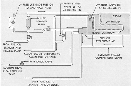
12B5. Fuel system. a. Description. The fuel
oil supply system is composed of a standby and
priming pump, an attached fuel oil pump, and a
fuel oil strainer-filter with the necessary relief
valves and piping.
The standby and priming pump is used to
fill the complete fuel system prior to first starting the engine or after the engine has been over
hauled. As the engine starts to turn, the attached
fuel oil pump takes over the task of supplying
fuel to the engine and forces the fuel past a
relief bypass valve through the fuel oil strainer-filter to the engine header where each individual
injection pump is supplied. The overflow from
this header is directed, via a relief valve, to the
clean fuel oil tank. Dirty oil from the injection
nozzle compartment flows back to the leakage
tank or to the bilges depending on the particular installation.
that a sufficient velocity of fuel is obtained in
the fuel oil header to insure rapid replacement
of fuel as it is used by each individual injection
pump at full speed.
b. Fuel pump. The attached fuel oil supply
pump is a positive displacement pump. It should
require no attention other than an occasional
inspection. The packing gland should be tightened or repacked as found necessary. It is very
important when installing pump packing that
the rings be cut to the exact lengths. The joints
of the packing should be alternated so that they
do not come in line with each other. Leakage
should be permitted through the gland after the
packing is first installed. The gland should then
be set up in small increments with several minutes between tightening in order to permit the
packing to adjust itself to the shaft gradually.
c. Injection system. The injection system
for each cylinder is made up of the injection
pump, injection nozzle, and the tubing connecting the two units.
1. The injection pump is of the constant
stroke, lapped plunger, cam-actuated type and
is identical in principle to the pump used on the
Model 38D 8 1/8 engine. The pump measures
the correct amount of fuel and delivers it at the
correct moment to the injection nozzle from
which it is injected into the combustion space
between the pistons.
The injection pumps are enclosed in the
cylinder block in an inverted position on the
control side of the engine below the camshaft.
The camshaft is driven through a silent chain
by a sprocket on the control end of the upper
crankshaft. Each pump consists of a housing,
plunger, barrel, control rack, plunger spring, delivery valve, delivery valve seat, and delivery
valve spring. The push rod assembly transforms
the rotary motion of the camshaft into linear
up-and-down motion of the plunger.
The injection pump plunger moves in the
plunger barrel with a constant stroke and delivers fuel through the delivery valve and injection tubing to the injection nozzle and on to the
combustion space in the cylinder liners. The
254
plunger stroke remains constant, and the amount
of fuel is varied by rotating the plunger in the
barrel by means of the serrated control rack
acting upon and meshing with the pump plunger
control sleeve.
When the plunger is in its highest position,
the fuel inlet port is uncovered and the pump
barrel fills with fuel. As the plunger moves
down, the port is covered and fuel is delivered
to the combustion space. Delivery of fuel continues until the helical edge of the plunger uncovers the bypass port. Fuel not required for
combustion is discharged through the bypass
port to the suction header. (See Figure 5-23.)
The exact position in the plunger stroke at
which the helical edge uncovers the bypass port
depends on the rotary position of the plunger.
When the plunger is in the stop or no fuel
position the vertical groove and the helical edge
of the plunger keep the bypass port uncovered
during the entire plunger stroke, bypassing all
the fuel.
Rotary position of the plunger is controlled
by the regulating governor through its linkage
with the fuel control rod and injection pump
control rack. The control rack is connected to
the fuel control rod of the governor linkage at
the shifter sleeve and to the injection pump at
the plunger control sleeve. The sleeve is toothed
at one end and slotted at the other end. Lugs
on one end of the pump plunger fit into the slots
of the control sleeve.
For an increase in fuel, the shifter sleeve
moves the control rack through the shifter sleeve
key. For a decrease in fuel, the control rack is
moved by the control rod shifter sleeve spring.
This flexible design is used to actuate the control racks so that if any of the racks sticks while
the engine is running, the remaining pumps can
be operated to decrease the fuel injected.
In order to cut out any individual pump
while the engine is in operation, the shifter sleeve
should be rotated until the slot in the sleeve
can pass over the sleeve key of the fuel control
rod. This will permit the movement of the individual control rack to the stop or no fuel
position.
The delivery valve seats when the pressure
of oil in the pump chamber is relieved. Because
of the spring and the high oil pressure in the
discharge tubing, no oil can drain out of the tubing. The seating of the delivery valve causes the
injection nozzle to close sharply and prevents
a dribbling of oil from the nozzle.
2. The fuel injection nozzle consists primarily of a nozzle body, nozzle spring housing,
needle sleeve, needle, push rod, spring, filter,
shim and nozzle tip. On the down stroke of the
injection pump plunger, fuel enters the injection
nozzle through the injection tube and is forced
through the nozzle filter. The nozzle filter removes any foreign matter which may have gone
through the main filters.
The filter built into this nozzle is extremely
simple. It is a close fit in the nozzle body with
a clearance of .0015 in. to .0022 in. for fuel to
pass from one groove to another. The longitudinal grooves are connected alternately with
the annual grooves so that fuel entering the
annular groove is forced through the space between the filter and the nozzle body into the
annular groove connected to the opposite end of
the filter. The filtered fuel is forced into the
chamber through the flutes and holes, into the
outside of the needle sleeve where it enters the
chamber at the face of the needle seat.
The fuel under pressure acts against the
face of the needle lifting it from its seat. The
pressure of the oil is counteracted by the spring
through the nozzle push rod. This permits the
pressure of the fuel to build up to about 3000 lb.
When it reaches this point, the nozzle needle
opens, allowing fuel to escape through the three
small holes in the nozzle tip into the combustion
space of the cylinder in a fine spray. The fast
action of the needle caused by the fuel, acting on
the face of the needle, and the spring counteracting this pressure, insures quick opening and
closing of the needle and eliminates dribbling or
leaking.
12B6. Lubricating oil system. a. Description.
Lubricating oil is supplied to the system under
pressure to insure a continuous flow of oil to all
surfaces requiring lubrication and to the pistons
for cooling. The system is comprised of the attached lubricating oil pump, oil pan, strainer, oil
separator, filter and cooler with the necessary
valves and piping.
An oil gage connection to the gage board
255
is provided from the discharge of the lubricating
oil pump and upper oil header. A marked oil
gage stick is located at the control end of the oil
pan for checking the level of the oil in the
engine.
The lubricating oil pump, located on the
control end of the engine, draws oil from the oil
pan through a strainer and discharges it through
the filter and cooler to the lower and upper oil
headers. Through branches from these headers,
oil is supplied to each main bearing and to the
thrust bearing. From the main bearings, oil
passes through holes drilled in the crankshaft
and through tubes swedged into the crankshaft
to each crankpin bearing. Oil is then forced
through the passages drilled the length of the
connecting rod to the piston pin needle bearings
or bronze bushing and to the piston oil pockets
for cooling the pistons. An opening through the
upper crankshaft lubricates the timing chain.
The cooling oil from each lower piston is
discharged through the piston cooling bracket
outlet pipe into the sump or oil pan. Oil from
each upper piston is discharged through the
piston cooling bracket outlet pipe into the upper
crankcase compartment where it can drain toward either end of the engine and flow back to
the engine sump.
Branches from the lower oil header supply
oil to the thrust bearing, crankshaft vertical
drive gears, and main bearings. The bushings of
the flexible pump drive located on the control
end of the lower crankshaft, receive lubrication
through an opening in the lower crankshaft from
the control end main bearing. The surfaces of
the lower thrust bearing shell and the crankshaft
flange are lubricated by openings in the bearing
shell.
Connections from the upper oil header supply lubricating oil to the vertical drive gears and
bearings, to the blower flexible drive wear rings,
to the inner and outer blower impeller bearings,
and to the injection pump tappet housing. The
blower drive gears are lubricated by a splash
system obtained from a special fitting that directs a spray of oil to the gears.
Fittings at the control end of the upper oil
header supply lubrication to the timing chain
and control mechanism. This oil drains down
and also lubricates the governor drive and gears,
circulating water pump, lubricating oil pump,
fuel oil and generator bearing drain pumps. A
tube from the upper header supplies oil to the
automatic timing governor for the operation of
that unit.
The camshaft and stub shaft bearings are
lubricated by pipes from the upper oil header to
the first bearing of each shaft. Oil enters the
hollow shafts and lubricates the rest of the bearings through openings drilled radially in the
camshaft.
Used oil from the bearings, tappet housing,
and pistons collects in the upper crankcase compartment where it drains either toward the control end or toward the blower end of the block
and flows back to the oil pan. Used oil from the
blower gears and bearings collects at the bottom
of the blower inner bearing plate and at the
bottom of the blower end cover. An oil tube
connects the blower end cover compartment to
the inner bearing plate compartment allowing
oil to drain from these areas to the oil pan, via
the vertical drive compartment.
An oil separator is fastened inside the
blower end cover and vents the crankcase of
fumes.
b. Lubricating oil pump. The lubricating
oil pump is attached to the pump mounting
plate on the control end of the engine below the
exhaust nozzle. It is of the positive displacement type, driven by a pump driveshaft through
the flexible coupling. A built-in relief valve is
set to operate at 60 pounds' pressure to relieve
the pump when excess pressure is built up. Oil
from the relief valve flows directly into the oil
pan.
The pump should require very little attention except for periodic removal for inspection
and the cleaning and grinding of the seat of the
relief valve with the tool furnished for that purpose. When reassembling the pump, carefully
adjust the valve to open at the proper pressure.
Special pullers are furnished among the
tools for removing the drive gear, the timing
gear, and drive coupling. Spanner wrenches are
provided for removing the locknuts on the drive
gear, the timing gear, and coupling.
c. Generator bearing drain pump. A small
gear type drain pump, mounted on the front of
the attached lubricating oil pump at one end of
the fuel pump housing, is driven by a beveled
gear on the extension of the upper impeller
shaft of the lubricating oil pump. This pump
takes the warm used oil from the closed generator bearings and returns it to the engine oil pan.
Cool filtered oil is furnished to the generator
bearings by the lubricating oil pump.
d. Suction strainer. The lubricating oil
suction strainer is located in the pump intake
line. All oil from the oil pan passes through the
strainer before entering the pump. The strainer
consists of a piece of screen supported by a
cylindrical shell which is fastened in the enlargement in the oil piping. This strainer should
be removed and cleaned frequently to insure an
adequate supply of clean oil to the pump.
12B7. Cooling system. a. General. An adequate supply of cool, clean, soft, fresh water,
free of scale-forming ingredients, is essential for
proper operation of the engine. The sodium
dichromate water treatment should be used.
Salt water should not be used for cooling the
engine.
The cooling system is of the closed type in
which fresh water is circulated through the engine and fresh water cooler. Salt water is circulated through the fresh water cooler and through
the generator air cooling system. For more detailed discussion, the two systems are discussed
separately. In older installations, salt water is
used as the cooling agent in the lubricating oil
cooler, but in later installations, fresh water is
used.
b. Salt water system. The salt water system consists of an attached salt water pump
which is driven through the flexible drive from
the lower crankshaft. It draws water from the
suction sea chest and strainer, forces it through
the generator cooling system, the fresh water
and sometimes the lubricating oil coolers, and
discharges it overboard. The necessary piping,
fittings, and valves complete the system. A
hand-operated three-way bypass valve is installed in the discharge piping from the pump to
the cooler, controlling the amount of salt water
passing through the coolers and thereby, to
some extent, the temperature of the fresh water
and lubricating oil to the engine.
Since the salt water and fresh water pumps
are identical they are discussed together under
the fresh water system.
c. Fresh water system. The attached fresh
water pump is driven through the flexible pump
drive from the lower crankshaft and draws
water from the fresh water cooler and forces it
into the engine at the base of the exhaust
nozzle. From the exhaust nozzle, water flows
around the jacketed outside of the exhaust
manifold, thence through fittings into the space
between the cylinder liner and jacket on each
cylinder. The heat of combustion is transferred
to the cooling water as it travels up and around
the cylinder liner, injection nozzle, air start
check valve, and cylinder relief valve. The
water leaves the jacketed space of the liner by
means of outlet pipes connected to the water
header on the side opposite the control side of
the engine. The water flows past a mercury
bulb thermometer where the outlet water temperature of the engine is registered.
Adjustments are possible so that part of
the water can be bypassed around the cooler by
means of a temperature regulator similar to that
used on the Model 38D 8 1/8 engine. All of the
cooling passages of the engine can be drained
at the exhaust nozzle. The system should be
drained if the engine is to be left in freezing
temperature with no protection.
d. Circulating water pumps. The pumps
are of the centrifugal type with the water entering at the center of the impeller and being
forced outward by the rotating motion of the
impeller vanes to the pump discharge.
These pumps require very little servicing
beyond the tightening or replacing of the packing and the oil retainer ring. The packing should
be tightened occasionally to keep the gland from
leaking. If it must be replaced, the special
packing hook should be used to remove the old
packing. The new packing should be cut to the
correct length and the joints alternated so they
do not come in line. The gland nut should then
be tightened in small increments to allow the
packing to adjust itself gradually to the shaft.
The bearings of these pumps are lubricated
from the gear drive case.
12B8. Air starting system. The air starting
system is furnished with air from the ship's high-pressure air line or from air bottles. A reducing
258
valve (3000 to 250 psi), a relief valve, gages,
and necessary valves are in the piping leading
to the engine. On the engine the control valve,
the air start distributor, engine starting air
header, pilot air tubing, and air start check
valves, complete the system.
Engine starting is accomplished by the action of the compressed air on the pistons in their
proper firing order. The operation is identical
with that described in Chapter 4 for a Model
38D 8 1/8 F-M engine. When the hand control
lever of the fuel and governor control rod is
moved from STOP to START position, the
machined portion of the control valve plunger
acts as a cam, forcing the control valve open,
allowing high-pressure air to enter the engine
starting air header and the air start distributor.
The air chamber of the distributor housing the
pilot valves is under pressure when the control
valve is open. This pressure is greater than the
force exerted by the valve springs and accordingly it forces the pilot valves down against
the air start cam.
The cam is designed so that the pilot
valves on high cam are closed and vented to the
atmosphere. The pilot valves on low cam are
open, allowing pilot air to enter the pilot tubing
from the distributor air chamber. The rotation
of the cam, which is driven through the flexible
pump drive from the lower crankshaft, causes
the pilot valves to open in time with the engine
firing order, admitting pilot air up to the air
start check valves. The action of this valve allows a full charge of air from the main engine
starting air header to enter the combustion
space in the cylinder liner, forcing the pistons
apart and rotating the crankshafts.
When the engine begins to fire, the hand
control lever is moved from START to RUN
position. This raises the control valve spring to
close the valve, shutting off the air to the engine
header. The engine starting air header and air
start distributor are vented to the atmosphere
through an opening in the control valve. When
the pressure is relieved on the air chamber, the
valve springs raise the pilot valves free of the
cam, thereby venting all pilot tubing to the
atmosphere.
The control valve located in the engine
header is held closed by the combined action of
the valve spring and high-pressure air. The
valve is opened when the hand control lever is
moved from STOP to START position. The
clearance between the valve plunger and the
valve stem should be 1/16 in. This clearance
can be adjusted by adding or removing shims
between the valve body and plunger body.
The valve will require little servicing beyond its removal, and reseating of the valve seat
with the tools furnished for this purpose. After
the valve seat has been refaced, the valve
should be lapped to make a positive seat and
prevent leakage of air from the air inlet piping.
The air start distributor, located on the
side opposite the control side of the engine
below the exhaust manifold at the control end,
is properly timed and marked at the factory.
The distributor directs a flow of air into the
combustion chamber of the engine in time with
the engine firing order. Under normal circumstances it will not need to be timed again; however, should a new cam be installed, it must be
retimed.
The air start check valve is located in the
cylinder liner, at the injection nozzle level, on
the side opposite the control side of the engine.
It is actuated by a supply of pilot air from the
air start distributor which acts against the pressure of the valve spring forcing the operating
piston to open. When the piston opens, it releases a charge of air from the engine starting
air header to the combustion space between the
pistons in the cylinder liner, forcing the pistons
apart and causing the crankshafts to rotate.
When the air start distributor shuts off the
supply of pilot air to the valve, the spring closes
the operating piston. The air from the engine
starting air header presses against the balancing
piston with greater force than it does against
the check valve so that at no time is there
enough pressure to open the valve.
The valve is vented to the atmosphere
through two holes in the valve body. Water
from the cylinder liner jacket enters the space
between the check valve sleeve and the sleeve
water jacket to cool the valve and valve body.
12B9. Exhaust system. The exhaust system
conducts the gases from the engine combustion
space through the exhaust ports to the
259
atmosphere. The hot gases are forced out of the cylinder liner when the upper and lower pistons
uncover the exhaust and inlet ports The gases
enter individual exhaust decks connected to the
exhaust manifolds mounted in the cylinder
block on each side of the engine. The gases pass
on through the combined exhaust nozzle at the
control end of the engine to the exhaust pipe
and on to the atmosphere, usually through one
of the main engine exhaust valves. The exhaust
deck castings and welded exhaust manifolds
contain water jackets far the passage of cooling
water from the welded exhaust nozzle, through
which the water enters the engine. A drain plug
is provided in the exhaust nozzle for draining
any condensation in the nozzle, manifold, or exhaust
line. All of the cooling water passages of
the engine can be drained through a plugged
hole in the exhaust manifold. The exhaust
decks and manifolds are doweled in place so
that they will line up with other parts after
removal or replacement.
The exhaust manifolds are provided with
openings at each cylinder for inspection and
cleaning purposes. Plain flange covers are furnished for those openings for the side opposite
to the control side of the engine. The covers
on the control side are quipped with pyrometers. These instruments indicate the temperature of the exhaust gases leaving the exhaust
ports of each cylinder on a single selector indicator on the control board.