9A1. General. Although the, submarine
operates in large bodies of sea water, the use
of salt water aboard the submarine is limited.
Water, free of salt and other impurities, is
used for cooling the diesel engines and in the
crew's cooking, drinking, and bathing facilities. The torpedoes and the torpedo firing
mechanisms, as well as the vacuum pump
tank, use distilled water. Distilled water is
also needed for the battery cells.
The water for all these operations is
either carried by the vessel or is distilled
on board. The purpose of the water system
is to store, distill, and distribute water to
the equipment requiring it. (See Figure
A-8.)
B. FRESH WATER SYSTEM
9B1. General description. Two of the four
main tanks of the fresh water system are
located in the forward end of the forward
battery compartment, and two in the after
end of the control room below the platform
deck. Fresh water tank No. 1 is located between frames 35 and 36 on the starboard side,
tank No. 2 between frames 35 and 36 on the
port side, tank No. 3 between frames 57 and
58 starboard, and tank No. 4 between frames
57 and 58 port.
The fresh water tanks are connected by
means of the fresh water filling and transfer
lines. Supply branches connect to the three
emergency tanks, lavatories, sinks, showers,
scuttlebutts, galley equipment, distilling
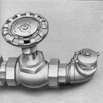
Figure 9-1. Ship's fresh water filling valve.
plant, and the diesel engines. A cross connection is provided between the filling and transfer lines of the fresh water system and the
filling and transfer line of the battery system.
Two 60-gallon emergency fresh water
tanks are located on the port side in the forward
torpedo room. One 130-gallon emergency fresh water
tank is located on the port
side in the after torpedo room. These tanks
are connected to the fresh water system, while
the 18-gallon emergency fresh water tank in
the control room, and the 8-gallon emergency
fresh water tank in the maneuvering room
have no connections to the fresh water systems.
The fresh water filling valve and hose
connection (Figure 9-1), located in the gun
access hatch, connects with the fresh water
filling and transfer lines extending to the
forward and after ends of the vessel. In the
forward torpedo room, the fresh water main
has connections to the No. 1 and No. 2 fresh
water tanks. It also has connections to the
two 60-gallon emergency fresh water tanks,
the crew's lavatory, and the torpedo filling
connections. The 60-gallon emergency fresh
water tanks are equipped with their own
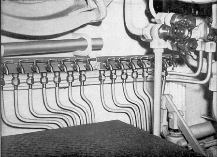
torpedo filling connections. The quantity of
water in the No. 1 and No. 2 fresh water
tanks is measured by try cocks located on
the after bulkhead of the forward torpedo
room. (See Figure 9-2.)
In the officers' quarters, the fresh water
main supplies fresh water to the officers'
pantry, the shower, the lavatories, and the
hot water heater.
99
Figure 9-2. Try cocks.
In the control room, the fresh water connections are to the fresh water tanks No. 3
and No. 4 below decks, and the fresh water
transfer cutout valve from No. 3 and No. 4
fresh water tanks. The cross-connection
valve between the fresh water system and the
battery fresh water system is also in the
control room overhead.
In the crew's quarters, the fresh water
supply connections are to the galley equipment, scuttlebutt, scullery sink, and coffee
urn. In the after end of the crew's quarters,
the fresh water main supplies water to the
two lavatories, showers, and the hot water
heater.
The water main in the forward engine
room is equipped with valves and connections
to the distilling plants, and to the forward
engine cooling system and purifiers.
In the after engine room the fresh water
main is equipped with valves and connections
to the after engine cooling system and purifiers.
There are no fresh water connections in
the maneuvering room. The fresh water main
aft terminates in the after torpedo room
where it supplies water to the emergency
fresh water tank, the after torpedo filling
connection, and crew's lavatory. The emergency
fresh water tank is equipped with its
own after torpedo filling connection.
9B2. Hot water system. Water for washing
and cooking is heated by electric heaters.
There are three electric hot water heaters.
One heater with a 20-gallon tank is located
in the starboard after corner of the control
room; two heaters each with 25-gallon tanks
are located one in the starboard forward corner
of the forward battery compartment, and
the other in the port after corner of the after
battery compartment. Each heating unit is
supplied with cold water from the fresh water
mains.
100
C. BATTERY WATER SYSTEM
9C1. Purpose. The cells of the forward and
after storage batteries must be filled periodically
to maintain a safe level of liquid.
The time between fillings is dependent upon
battery use and operating conditions. The
water used in the battery cells must be free
of minerals and impurities which, while harmless
to human beings, may react with the
battery acid and plates to cause corrosion
and breakdown of the battery cells. Therefore,
only the purest distilled water may be
used for refilling the batteries.
The purpose of the battery water system
is to store and supply distilled water to the
forward and after batteries.
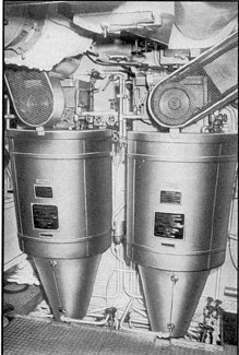
9C2. Description and operation. The battery
water system consists essentially of two
groups of four tanks each, filling and transfer
lines, and valves and branch piping with hose
connections for filling the individual battery
cells. The four forward battery water tanks,
Nos. 1, 2, 3, and 4, are located below deck
in the forward battery compartment and are
arranged in tandem, two on the port side and
two on the starboard. The after battery
water tanks are arranged similarly to the
forward battery water tanks with No. 5 and
No. 7 battery water tanks located on the
starboard side, and No. 6 and No. 8 tanks
on the port side. The battery water filling
valve and hose connection are located in the
gun access trunk. A cross connection in the
control room enables the battery water system
to be supplied from the fresh water
system. The battery water filling line divides
into the forward and after supply lines, supplying
water directly to their respective tanks.
The supply line to the after battery water
tanks is connected to the distilling plant,
providing an additional supply of distilled water
for the batteries when the distilled water in
the battery water tank is consumed.
The battery cells are filled by means of
a hose which is attached to the battery filling
connection, located on the battery filling line
connecting the port and starboard tanks. The
tanks are so interconnected that any one of
the tanks can be used to supply the cells in
either of the two battery compartments. Each
of the two pairs of starboard and two pairs
of port tanks is equipped with capacity gages
accessible from the battery spaces.
D. GALLEY EQUIPMENT
9D1. Galley and scullery sinks. The officers'
pantry, the galley, and the crew's mess room
are provided with sinks. Each is supplied
with hot and cold water. The sink drains
are connected to the sanitary drainage system.
9D2. Coffee urn. The crew's mess room is
provided with a 5-gallon electrically heated
coffee urn with a tap for drawing coffee in
the mess room. A cold water line supplies
the urn with water.
9D3. Scuttlebutt. The main drinking water
dispensing equipment aboard the submarine
is the scuttlebutt, or the drinking fountain.
One scuttlebutt is located in the officers'
pantry, and one in the crew's mess room. Each
scuttlebutt is provided with a cold water supply
line and drain to the sanitary tank
drainage system. Before the water enters the
scuttlebutt in the mess room, it is passed
through a cooling coil located in the cool room.
The water for the scuttlebutt in the officers'
pantry is cooled by the small refrigerator in
the pantry.
9D4. Lavatories and showers. Each
lavatory is provided with one cold water line, a
hot water line, and a drain to the sanitary
tank. There is one lavatory in the forward
torpedo room, two in the officers' quarters,
one in the commanding officer's stateroom,
one in the chief petty officers' quarters, two
in the crew's quarters, and one in the after
torpedo room.
The showers are provided with hot and
cold water. The deck drain for each shower
is connected with the sanitary tank drainage
system. There is one shower in the starboard
forward corner of the officers' quarters and
two showers in the after end of the crew's
quarters.
101
E. PLUMBING
9E1. Sanitary drainage. All lavatories,
sinks, showers, scuttlebutts, and heads drain
into No. 1 and No. 2 sanitary tanks through
the sanitary drainage system consisting of
the sanitary drainage piping and valves. The
No. 1 sanitary tank, located inside the MBT
No. 1 has two sanitary drainage mains
connecting to it, one on the starboard and one on
the port side. The starboard main to No. 1
sanitary tank receives the drainage from the
commanding officer's lavatory, wardroom,
stateroom No. 1 lavatories, and the officers'
shower. The port drain receives discharge
from the chief petty officers' lavatory, wardroom,
stateroom No. 2 lavatory, the forward
torpedo room lavatory, the refrigerator, and
the pantry sink.
The No. 2 sanitary tank, located in the
after starboard end in the after battery
compartment, receives the drainage from the
sanitary drain which collects the discharge from
the following: the galley sink, the scullery
sink, the scuttlebutt, the crew's lavatories,
the shower, and the washroom decks. The
officers' head in the forward torpedo room
empties directly into the No. 1 sanitary tank;
the after head in the crew's quarters empties
into the No. 2 sanitary tank. The forward
head in the crew's quarters and the head in
the maneuvering room discharge directly to
the sea.
F. HEADS
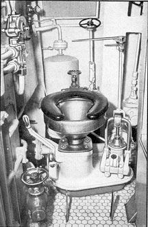
9F1. Expulsion type head. There are two
air expulsion type water closets (heads), each
Figure 9-3. Expulsion type head.
fitted with an auxiliary hand pump, one in
the crew's quarters, and one in the after end
of the maneuvering room. (See Figure 9-3.)
The water closet installation consists of
a toilet bowl over an expulsion chamber with
a lever and pedal controlled flapper valve
between, which is weighted to hold water in the
toilet bowl and seats with pressure of the
expulsion chamber.
Each installation operates as a separate
unit with its own flood, blow, and discharge
lines. The toilet bowl is provided with a sea
flood with stop and sea valves. The expulsion
chamber has a discharge line with swing
check, gate, and plug cock valves. The blow
line to the expulsion chamber receives air
through a special rocker valve which, when
rocked in one direction, admits air from the
low-pressure air service line into a small
volume tank until a pressure of approximately
10 pounds above sea pressure is reached.
When rocked in the opposite direction, the
rocker valve directs the volume of air into
the expulsion chamber. A sea pressure gage,
a volume tank pressure gage, and an instruction
plate are conveniently located.
Before using a water closet, first inspect
the installation. All valves should have been
left shut. Operate the bowl flapper valve to
ascertain that the expulsion chamber is empty.
102
Shut the bowl flapper valve, flood the
bowl with sea water through the sea and stop
valves, and then shut both valves. After using
the toilet, operate the flapper valve to
empty the contents of the bowl into the
expulsion chamber, then shut the flapper valve.
Charge the volume tank until the pressure is
10 pounds higher than the sea pressure. Open
the gate and plug valves on the discharge line
and operate the rocker valve to discharge the
contents of the expulsion chamber overboard.
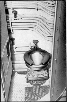
Figure 9-4. Gravity flush type head.
Shut the discharge line valves and leave the
bowl flapper valve seated. For pump expulsion,
proceed as previously stated except that
the contents of the waste receiver are to be
pumped out after the gate and plug valves
on the discharge line have been opened.
If, upon first inspection, the expulsion
chamber is found flooded, discharge the
contents overboard before using the toilet.
Improper operation of toilet valves should be
corrected and leaky valves overhauled at the
first opportunity.
9F2. Gravity flush type head. There are
two gravity flush type water closets (heads),
one in the forward torpedo room for the
officers, and one in the after end of the crew's
quarters. (See Figure 9-4.)
The water closet installation consists of
a toilet bowl over a waste receiver with a
lever and pedal-controlled flapper valve
between, which is weighted to hold water in
the toilet bowl and seats with the pressure in
the tank.
Each toilet bowl is provided with a flood
line with stop and sea valves. The water
closets are located over the sanitary tanks
and discharge directly into them.
Before using a water closet, first inspect
the installation. All valves should have been
left shut. Operate the bowl flapper valve to
ascertain that the waste receiver is empty.
Shut the bowl flapper valve, flood the
bowl with sea water through the sea and stop
valves, and then shut both valves. After using
the toilet, operate the flapper valve to empty
the contents of the bowl into the waste receiver
and sanitary tank.
G. DISTILLATION
9G1. Submarine distilling equipment. The
distillers in use on modern submarines are
either the Kleinschmidt Model S, or the
Badger Model X-1. Two stills are installed
on all later class submarines. The Kleinschmidt
model is discussed and illustrated
in this text. (See Figure 9-5.)
9G2. Consumption of fresh water. A modern
submarine during a war patrol will
consume on the average approximately 500
gallons of fresh water per day for cooking,
drinking, washing, and engine make-up water.
In addition to this consumption, the main
storage batteries require about 500 gallons
103
of battery water per week; giving a total
requirement of at least 4000 gallons per
week. This minimum requirement will allow
each man in the crew to have a bath at least
twice a week.
9G3. Fresh water stowage capacity. The
normal fresh water stowage capacity is about
5400 gallons; 1200 gallons of this is battery
water and is stored in the battery water
tanks. This water will last only about 10 days
and it is good practice not to allow the fresh
water on hand to drop below one-half the
normal capacity. The area of operations is
usually the determining factor as to when
the distillers can be used.
9G4. Principles of distilling action. The
knowledge of distilling liquids comes from
ancient days. Distillation is simply the
boiling of a liquid and the condensing of its vapor
to the liquid state again. In the boiling, much
or all of any impurities or undesired contents
are left behind, so that the condensed liquid
is free of them. If a teaspoon is held in a
cloud of steam arising from a teakettle, the
vapor will condense on the spoon and the
resulting liquid is distilled water.
9G5. The purifying action in distilling sea
water. In sea water, salt and other substances
are dissolved or held in solution. Sea
water does not boil at the same temperature,
212 degrees F, as does fresh water, but at a
temperature a few degrees higher. When the sea
water boils, it is only the water (H2O) that
is vaporizing at this temperature, and if that
pure vapor is led to another clean container
where it may condense, the result: is pure
distilled water. The salt (sodium chloride) and
other solid ingredients of the sea do not
vaporize and hence do not come over into the
distilled water.
9G6. Brief explanation. A brief
explanation is given of the actions that take place
in the Kleinschmidt still, without mentioning
mechanical details, in order that these actions
may be easily understood.
The distilling process in the Kleinschmidt
still is continuous, with sea water being supplied
at the rate of about a gallon per minute.
The distiller can be supplied with feed water
from the main engine salt water circulating
pump sea suction, from the main motor circulating
water system, and from the ship's
fresh water system. The latter feed is used
when redistilling ship's fresh water for battery
use.
Part of the sea water flows out of the
still as distilled water, and collects in the
distillate tank. It can be transferred by blowing
to the fresh water system or to the battery
water system for stowage.
Figure 9.5. Kleinschmidt distillers.
The desuperheating tank, the purpose of
which is to supply the cooling water to the
still and to lubricate the lobes of the
compressor at the top of the still, can be
replenished from the distillate tank. The remaining
sea water is concentrated brine and flows out
separately.
Inside a cone-like casing, a long length
of tubing is coiled. This casing is set with
104
the small end down. Actually there are ten
such cones, nested together. Cold sea water
enters at the bottom between the cones; that
is, it flows around the outside of the tubing.
Here, on its way up, it is heated, so that it is
boiling when it emerges from between the
cones at the upper end. The vapor is led
through a vapor separator into a compressor,
where it is compressed, and is then discharged
down into the inside of the tubing. On the
way down through the tubing, this vapor is
gradually cooled by contact with the colder
tubing walls, finally condensing therein and
flowing out as pure distilled water to a
storage tank. The nested cones of tubing,
therefore, act as a heat exchanger. The distilled
water is technically known as distillate or
condensate.
9G7. Necessity of compressing the vapor.
A question may arise as to why the vapor
is compressed in the still. The explanation
involves several considerations:
The conical crest of tubes serves three
purposes: 1) vaporization of the feed water,
2) condensation of the vapor, and 3) cooling
of the hot condensed liquid to a lower
temperature. In the lower part of the nest, the
feed water is at the temperature of sea
water; the temperature increases during the
upward flow, so that the feed water leaves
the nest boiling. The feed water in the upper
part of the nest is therefore very hot. On the
downward flow, the vapor is condensed in the
upper part of the nest, and in the lower part
of the nest, the hot condensed liquid is cooled.
Sea water does not boil at the same
temperature, for a given pressure, as does fresh
water, but at several degrees higher. The
feed water in the upper part of the nest is,
therefore, actually above 212 degrees F. But the
vapor from the boiling water is no longer
sea water; it is fresh water vapor, and fresh
water vapor at atmospheric pressure can
condense only at 212 degrees F. When a vapor is
compressed, its boiling point, or its condensation
point, rises. By compressing the vapors in
the still, its condensation point is raised above
the temperature of the hot feed water in the
upper part of the nest. Therefore, when the
compressed vapor enters the nest, it finds a
temperature lower than its new condensation
point, and so is able to condense. This type
of apparatus is accordingly called a vapor
compression still.
9G8. Heat input of still. Compression of
the vapor serves another purpose also. On
starting operation of the still, the feed water
is brought up to boiling temperature by the
electric heaters. After the still is in normal
operation, there will be a steady heat loss of
definite amount through the insulation and in
the outgoing condensate and brine overflow.
This heat loss is balanced by an input of
energy from the electric motor, which is
transformed to heat by the compression of
the vapor. Theoretically, this input of heat
by the compressor maintains the heat balance
at a constant level, and it is possible to
operate the still with all electric heaters turned
off. In actual practice, however, most of the
heaters are usually left on after the still is
in normal operation.
9G9. Vent to atmosphere. Since the boiling
of the sea water takes place inside the shell
of the still, it is necessary to prevent any
increase of pressure on the boiling water, for
increased pressure here would raise the
boiling point and put the whole system out of
balance and probably out of operation. The
situation is different in the compressor; when
the vapor goes into the compressor, it is
sealed off from the boiling liquid and may
then be compressed without affecting the
boiling point. Therefore, in order that the
boiling may always take place at atmospheric
pressure as found within the submarine, a
pipe called the vent leads from the vapor
separator and out through the bottom of the
still. This vent, being open to the atmosphere
at its end, insures that the pressure in the
vapor separator is always at the pressure of
the surrounding atmosphere. A distant
reading dial thermometer is connected by a
flexible tubing to the vent to give the
temperature in the vent pipe.
Although this open vent pipe leads
downward out of the still, the steam when in
normal amount inside will not flow out,
because of the pressure of the outer atmosphere
105
through the vent. Actually, the interior and
exterior pressures are so maintained that
there is a very small excess of pressure inside
the still. This causes a slight feather of steam
to appear at the vent, which is an indication
that the still is operating satisfactorily. Any
excess steam that the compressor cannot
handle, however, will be able to pass out
through the vent, which thus acts as a safety
device.
The vent pipe also serves to permit
drainage to the bilge of any slight amount of liquid
carried into the vapor by the violent boiling
action, and prevents it from gathering on
the floor of the vapor separator. A small drain
tube leading down from the compressor to
just above the vent pipe in the vapor
separator also permits water and oil to drain
from the compressor seal out through the
vent.
9G10. Portion of sea water not distilled.
All of the incoming sea water cannot be
distilled, for some must remain undistilled to
carry away the concentrated salt content left
from the distilled portion. This undistilled
portion, which is concentrated brine, is
maintained at a level just above the top coil of
the heat exchanger by overflow pipes. It flows
down through these overflow pipes into a
separate conical passage, called the overflow
heat exchanger, located around the nest of
tubes, where it gives up some of its heat by
conduction through the metal walls, thus helping
to heat the incoming feed water.
9G11. Overflow weir cup. The overflow
pipe, after leading out of the overflow heat
exchanger at the bottom of the still casing,
rises again a short distance. At the top of
the upright overflow pipe, the brine flows out
through an opening called the weir, which
meters or measures the quantity of brine
overflow in gallons per hour. The overflow
brine passing out of the weir falls into an
open cup and then drains down to a storage
tank called the brine receiver, from which it
is discharged to the sea.
Since water in any U-shaped container
must always be at the same level in both arms
of the U, the open weir is located at such a
height as to insure that the interior overflow
heat exchanger is always full of liquid, and
therefore always exerts its full heating effect
on the sea water inside.
9G12. Time required to start sea water
boiling in still. When starting the still, from 60
to 90 minutes are required to bring the
temperature up to the boiling point.
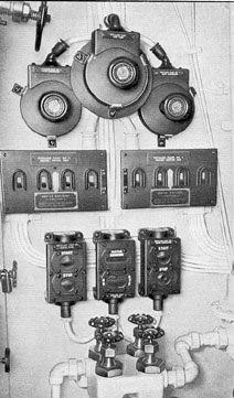
9G13. Heat balance in the still. It may be
interesting to indicate the heat flow through
Figure 9-6. Distiller controls.
the various parts of the still in actual
quantities. The following is an example:
Heat input: 10,185 Btu per hour come
in through the compressor; 5,940 Btu per
hour come in through the electric heaters.
This is after the still is fully operating. The
total input of heat is 16,125 Btu per hour.
106
Heat loss: This total quantity of heat
flows out through four separate paths, as
follows:
1,825 Btu per hour in condensate, 11,600
Btu per hour in overflow, 400 Btu per hour
from vent, 2,300 Btu per hour by radiation
from hot metal parts, or a total heat loss of
16,125 Btu per hour. The heat balance is not
always at this exact number of Btu per hour,
for various momentary changes or rate of
feed and temperature of sea water, voltage
fluctuations in motor, or other operating
conditions, will naturally cause it to vary around
any average number. This heat balance of
the still is very sensitive and all changes that
may be necessary in the operation conditions
should be made slowly.
9G14. Purity of the distilled water. If no
leaks are present, the distilled water will contain
only about one part of salt to a million
parts of water. The distiller cannot, of course,
remove any volatile liquids; that is, liquids
that boil at or below the boiling temperature
of water. For example, in badly polluted
harbors or streams, a trace of ammonia may
be present in the distilled water; and in
improperly chlorinated waters, a trace of
chlorine may likewise come over in the
distilled water.
9G15. Two-still system. In the complete
submarine distilling system, there are two
separate stills (Figure 9-6) each with its
necessary control devices.
Two stills are necessary, not only as a
safety factor, but also to provide sufficient
distilled water. These stills may normally be
run 300 to 350 operating hours without cleaning.
Each gives 40 gallons per hour. This
means a total of 24,000 to 28,000 gallons of
distilled water. The consumption of distilled
water is about 600 gallons per day for all
purposes. On a war patrol lasting 60 days,
the total consumption will be about 36,000
gallons, and may run higher in the tropics.
9G16. Water for the storage batteries.
Distilled sea water is fit for human consumption
and for the storage batteries. It may happen
that fresh water is taken on board from some
shore source. Such fresh water is not suitable
for storage battery use until it has been
distilled. Fresh water taken aboard in any
foreign port should always be boiled or distilled
before use. Only fresh water definitely known
to be pure may be used without distilling or
boiling for drinking, cooking, or personal
use. In distilling fresh water that is taken
aboard, the operation of the still is practically
the same as when distilling sea water, the
difference being that the overflow is returned
to the ship's fresh water tanks from the
brine tank instead of being discharged overboard.