33-1. Foreword. The type of investigation required immediately after a ship has been hit depends upon many factors including (1) the size and type of munition causing the damage, (2) where it hit, and (3) whether it exploded inside or outside the ship.
Certain information as to the extent of a casualty will be available almost immediately. Heavy shock and whipping of the hull structure may indicate a major underwater explosion, although intense vibration will not always occur from such casualties on large vessels. A decided or progressive change in trim or list, as indicated by clinometers, will also divulge information.
Additional information will come from gunnery and ship-control stations, and from roving patrols near the scene of the casualty. Thus, a turret may report that it is entirely without power, the bridge may report that steering control has been lost, and Repair III may report that water is seeping through a certain bulkhead.
The foregoing information is preliminary and superficial, but combined with reports from lookouts and other topside personnel it will locate the damage and give a general picture of its extent. There will, of course, be other signs of damage - A minor loss of power, a wisp of smoke, excessive warmth of a bulkhead, or slight leaking at a seam. All of these things must be investigated thoroughly. They are symptoms of damage conditions, and prompt remedial actions may be necessary if the ship is to survive.
33-2. Survey of the damage. Investigations must be thorough, but they should be conducted with caution. Ships have been lost, or have at least suffered unnecessary flooding merely because investigating personnel were rash and thoughtless in carrying out their duties. Repair parties should therefore be organized and trained in the investigation phases of damage control. On large ships it is customary to have sub-groups of a repair party detailed to investigate specific items. For example, electrician's mates should look for damaged electric circuits, especially those causing sparks. Another group should be trained and equipped to look
for fires and to commence fire-fighting operations at once, and still other men should be detailed to examine bulkheads and frames and to make rapid estimates of their remaining strength and integrity.
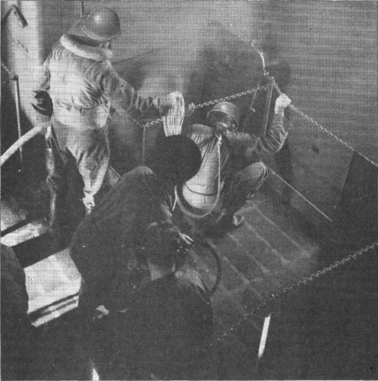
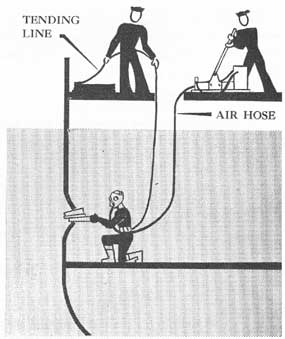
Any damaged area may be on fire, and will be almost certain to contain asphyxiating, toxic or combustible gases. The first man to enter the area should therefore be equipped with rescue breathing apparatus and be accompanied by a tender. He can make a rapid survey of the damage. He must be able to give information on damage which could result in destruction of the ship, such as fire and flooding, and on casualties that would interfere with limiting and repairing damage, such as the absence of light and the presence of smoke, fuel oil, wreckage and loose- stores. He should be an intelligent and well-trained man, because his report will have an important bearing on the steps that are taken to localize and to overcome the damage.
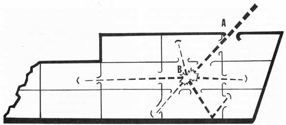
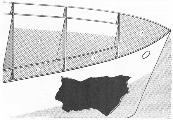
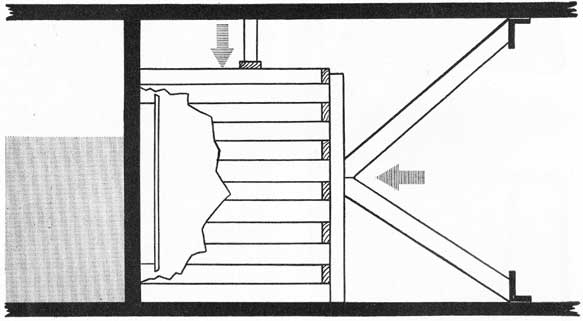
33-3. Casualties may not be immediately apparent. All damage-control personnel should understand that damage is almost invariably more extensive than a cursory examination would indicate. Consider the following example: A projectile or bomb strikes a vessel at A (see fig. 33-1), and passing forward and downward, explodes in compartment B. Investigation should cover all spaces along the path of the projectile, and include all systems and structures in every compartment immediately adjacent to B, and even to a depth of two or three compartments in all directions. This is to discover damage occasioned by shock and splinters, and to establish boundaries around the damaged area.
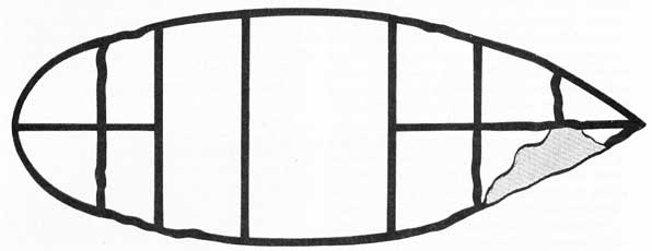
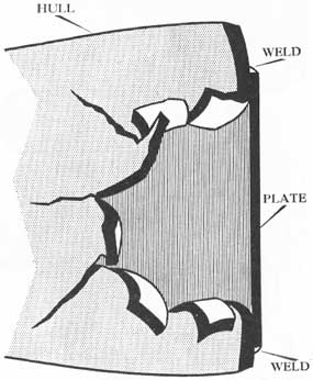
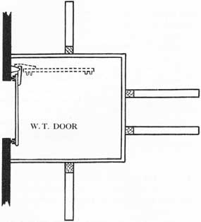
Consider also the case of a torpedo hit similar to that diagrammed in figure 33-2. In this case the major damage forward will be obvious. However, a large number of less apparent casualties will be present, and unless they are discovered and dealt with the ship may be lost through fire or progressive flooding. Seams, stuffing tubes and pipe lines will be opened over a considerable area, and on several types of light craft, shell or deck plating at some distance from the
246
Figure 33-A. Rescue breathing apparatus being employed to investigate damage in a smoke-filled compartment.
point of immediate damage may be cracked or buckled. Investigation must therefore be thorough and all-embracing.
33-4. Further investigation of damage. After the original investigator has made his report, steps must be taken to localize and to overcome the obvious damage, and to investigate for latent casualties. Repair personnel should provide themselves with protective equipment, lighting and ventilating facilities, and with such tools as are required.
Generally speaking, the following steps should be taken:
If fire is present, the fire-fighting party should begin
operations immediately. The ship is in grave danger, and no repair operations can be begun until the fire is extinguished. Men should wear rescue breathing apparatus while fighting fires in interior spaces.
Electric circuits in the damaged area should be de-energized, preferably by pulling switches in a compartment at a distance from the scene of damage. If this is not done short circuits may cause combustible gases to ignite. Power may be restored as soon as circuits are repaired or are tested and found to be intact.
Pipe lines in the damaged area are certain to be ruptured. Valves may be destroyed. If the lines are so
247
Figure 33-1. Example to illustrate the progressive nature of fragment damage incident to detonation of a bomb.
Figure 33-2. Diagram to illustrate possible buckling of plates incident to a torpedo hit.
badly damaged that they cannot be repaired at once by using soft patches or similar methods, the injured sections must be isolated outside the damaged area.
The air in a damaged area is certain to be fouled with smoke, fumes and gases, many of which will be injurious to personnel. Furthermore, a compartment may be so hot that repair personnel cannot remain in it. It may therefore be necessary to provide fresh air through the regular ventilation system, or by means of portable blowers, or by bleeding from the ship's service air lines. Hot compartments can be cooled by spraying them through fog nozzles, and men can be cooled by drenching their clothing or by playing streams of water on them from fog nozzles. Rescue breathing apparatus should be available, and should be worn if the need is indicated.
If the compartment is not on fire, and it is necessary
to employ spark-producing equipment in the area to make repairs, fire extinguishers should be brought to the scene, and the air should be tested for explosive vapors and for oxygen content before repair work is begun. Tests for poisonous fumes should also be made, so that personnel will not be overcome.
Investigators should report their findings to the officers-in-charge of their respective repair parties, who in turn should coordinate the information and pass it along to the damage control officer. The reports should be collated in damage-control station, so that immediate steps can be taken to isolate damaged systems, to attack casualties in the most logical manner, and to provide the right type of equipment for meeting the emergency. Portable sound-powered telephones are invaluable for maintaining communications between the scene of a casualty and the repair station.
248
Damage-control headquarters should sift the information obtained, and should prepare graphic records of the damage as reports are received. This can be done rapidly by marking the subdivision and access diagrams. A brief summary of the damage, containing data regarding remaining buoyancy and stability, speed available, reductions in gun power and probable results of the casualty should be transmitted to the Commanding Officer.
33-5. Soundings. The foregoing remarks apply largely to investigations made at the scene of the original damage. If investigations were no more thorough than those described above, a host of lesser injuries would go undetected, and a ship might be lost. The following additional steps should therefore be taken:
If the casualty involves penetrations of the underwater hull structure, all compartments, tanks and voids adjacent to the original point of damage must be sounded to determine which of them have been penetrated and flooded. It would be well to extend this examination to every compartment any part of which lies within fifty feet of the center of damage, and the investigation must be continued beyond the original estimated limits until an intact watertight boundary is discovered.
Complete flooding of a compartment, or flooding to sea level, will generally indicate that the compartment is open to the sea. Flooding to a lesser height will indicate that the puncture is relatively small, and that progressive flooding is in progress. This latter estimate can be verified by subsequent soundings. On some vessels, however, the foregoing may not always be true. In one case a non-isolated salt-water line leading through a void was ruptured, and the space flooded completely without having any access to the sea. Such a condition is equally dangerous, for in time the pressure within the space may reach fire-main pressure, with the result that undamaged bulkheads will collapse.
If the underwater explosion is severe, all voids, tanks, and lower compartments of the ship must be investigated. Rivets may be torn loose, plating may be cracked, seams may be parted, and bulkheads and shell plating penetrated at great distance from the principal point of damage. Furthermore, internal flooding may spread over a large area through improperly maintained or damaged watertight fittings.
Not all of these secondary casualties will be apparent during a hurried investigation. If water is on the opposite side of a bulkhead containing cracks or defective stuffing tubes, the damage may be readily detected. However, if flooding has not yet reached that
area the damage will not be obvious, and it may not come to notice until an unnecessary degree of progressive flooding has occurred. In one case a secured boiler room was flooded under these circumstances.
There should be a sounding detail in each repair party, and all of the personnel should know where and how to sound all spaces in their own and adjacent areas.
Soundings are taken with rods fastened to lines, or with folding or rolled metal tapes. When the bob on the end of the tape reaches the bottom of the tank, the liquid height is indicated by oil or water adhering to the tape. Soundings may be inaccurate because of foamy oil or rolling of the ship.
Under the conditions mentioned above, all fuel-oil tanks on the ship should be investigated for damage by taking thief samples of the oil and testing them for water. Likewise, potable and feed-water tanks should be tested for salinity. In some respects these tests give truer indications of damage than soundings do, for they will disclose even minor leakage. It is vital to the safety of the ship that the engineering department be aware of all fuel and water tanks contaminated by sea water, for otherwise someone may cut in on a defective tank.
Great caution must be exercised in removing the plug or cap from the upper end of a sounding tube, for if the damaged compartment is open to the sea and the outside water level is above the top of the sounding tube, water and possibly oil will rush out of an open tube. Instead of taking off the cap rapidly, back it off slowly. Look and listen. If a rush of air escapes around the threads while the cap is still under control, stop. You need no soundings to tell you that the lower compartment is being flooded; to permit more air to escape is to permit more water to enter the damaged space. If a trickle of water appears around the threads, you know that the compartment below is completely flooded. Therefore, in both cases, re-secure the cap and report your findings.
While investigating damage, never lose control of a watertight closure. In the foregoing case, had the cap been completely backed off, the upward rush of water would have prevented re-securing the cap in place, which in turn would have resulted in flooding of an upper compartment with possible serious consequences
33-6. Investigating structural damage.Structural damage should be investigated by personnel who are capable of assessing the damage and of planning and executing emergency repairs. Flooding is almost invariably the result of structural damage below the waterline. It is vital to limit that flooding in order
249
to keep the ship from sinking, and to remove as much of the flooding water as possible in order to restore buoyancy, stability, and a level gun platform.
Like soundings, investigation of structural damage must cover a considerable area surrounding the immediate scene of damage, not alone on the same level as the principal casualty, but likewise above and below it. The investigators should look for splinter holes, ruptured pipe lines, warped or fractured frames and stanchions, cracks, open seams, leaky stuffing tubes, bent shafts, improperly closed fittings, severed electric cables and the like, and should shore quickly any damaged bulkheads that give indication of requiring such support. Important discoveries should be reported at once to the officer-in-charge of the repair party.
Investigation of structural damage by visual examination presents many difficulties and dangers. In order to do a thorough job a man will often have to open one or more watertight doors or hatches. It is almost invariably unwise to open any such closures below the waterline in the vicinity of damage, and it should be done only after the best possible investigation by means of soundings, and after obtaining permission from the damage control officer. One injudicious move and the ship may be lost.
No watertight door, hatch, scuttle or manhole should be opened until it is known definitely that the compartment on the other side is either completely dry, or so little flooded that opening the closure will not permit flooding to spread. Unfortunately, many compartments are not provided with sounding tubes. However, this is no bar to investigation. Tapping on a bulkhead with a hammer will often disclose the presence of water on the other side; indeed, the exact height of water may be judged by variation in the tones produced when the bulkhead is struck at different levels. Men should occasionally tap various bulkheads for practice, to train their ears to the sound of bulkheads around undamaged areas. The tones will vary appreciably with the thickness of the plate.
Another method of examining a compartment for water is to back off an air-test cap - slowly, so as not to lose control of it if air or water appear.
A dangerous, but sometimes necessary method of testing a compartment for flooding is to back off slowly on some of the dogs which hold a hatch or a door closed. In one or two cases, personnel have made the irretrievable error of first loosening the dogs on the side of the door away from the hinges. The result was that the door bent or flew open, and another compartment was needlessly flooded. The correct
procedure is to slack away slightly on the dogs adjacent to the hinges. There is a slight amount of clearance around the hinge pins, and as the dogs are loosened, water, if any is present, will begin to trickle between the gasket and the knife edges on that side. Control is still maintained by means of the hinges and the opposite dogs. This method cannot be used with quick-acting doors and scuttles.
A compartment containing drain lines leading to pumps can often be tested for flooding by putting a suction on the space. If water is present it will show in the pump discharge; if the compartment is dry the check valve, if one is installed, will rattle. The investigator should assure himself that the drain suction line is not ruptured between the pump and the space under investigation.
33-7. Spreading of fire. As in the case of progressive flooding through damaged or improperly maintained fittings, fire, gas and smoke may be spread in a somewhat similar manner. Open flues such as trunks and ventilation ducts are potential sources of trouble. The latter are especially dangerous, for if they are not properly secured they will carry fire to other parts of the ship. It is therefore necessary to inspect a wide area around the scene of a fire so that damage may be localized.
From the foregoing remarks it may appear that after a casualty occurs the repair party spends the first hour investigating damage, and no time at all in localizing it or in effecting repairs. This is not true. Much of the damage is obvious within a few minutes, and given a well indoctrinated damage-control organization only a small number of men will be required to devote their entire time to such investigation. The remainder can begin remedial action.
After a casualty, adjacent repair parties will collaborate in inspecting the ship, and personnel on watch in manned spaces can examine the areas in which they are stationed.
The first two steps in handling a casualty are to put out fires and to control flooding. Without adequate investigation, no one will know what types and quantities of materials must be provided at the scene, which electric circuits and pipe lines must be isolated, and which partially flooded compartments can be made watertight and pumped dry. Working in a haphazard manner, without information or plan, a repair party will waste valuable time in attempting an impossible repair on one leak while six other compartments flood through the holes which could be stopped in a few minutes.
250
CHAPTER XXXIV
REPAIRING DAMAGE IN ACTION
34-1. Battle damage. It is very important to know methods of repairing damage during and immediately after action to the end that a ship may remain in the battle, or can return to base for extensive repairs. This discussion is not concerned with Navy yard or tender repairs, but with what ship's personnel can do themselves while they are still in the battle area.
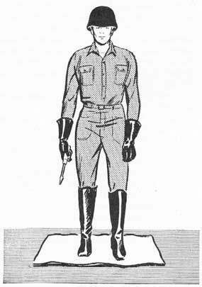
Figure 34-1. The well-equipped electrical repairman wears a helmet, insulated gloves and boots, and a full suit of dungarees. He stands on a rubber mat.
Some of the possibilities involved in battle damage are the following:
1. Large holes in the underwater hull.
2. Small holes and cracks in the underwater hull.
3. Holes in the hull above water.
4. Punctured, weakened or distorted bulkheads.
5. Flooded machinery spaces or other vital spaces.
6. Warped or sprung doors and hatches.
7. Weakened or ruptured beams, supports and other strength members.
8. Ruptured or weakened decks.
9. Wreckage interfering with function.
10. Ruptured or cracked pipe lines.
11. Severed electric cables.
12. Broken or distorted foundations under machinery.
13. Broken or pierced machinery units.
14. Fire, with its attendant heat, smoke and other damage.
The purpose of this discussion is to point out how damage-control repair equipment can be used to minimize the effects of the foregoing damage, to confine it, to restore buoyancy and stability, and to restore such services as water in fire mains, electric power and light, air pressure to guns, and suction on drainage lines. Many casualties may be partially nullified when no special tools are at hand, merely by using readily available materials and common sense.
GENERAL
34-2. Protection of repairmen. Provisions should be made to give repairmen adequate protection by means of proper clothing. Leather gloves of a gauntlet type are highly desirable to protect hands, and asbestos gloves for handling hot plates. Steel helmets and anti-flash clothing must be provided. Electrical repairmen should be protected by insulating gloves, boots and mats. It would be well for them to insulate their tools by wrapping them with rubber tape or friction tape. Insulation tubing removed from scraps of certain kinds of cable may also be used on some tools.
34-3. Investigating damage. After the ship has been hit, investigate damage thoroughly following the principles discussed in Chapter XXXIII. Start putting out fires and controlling flooding as soon as possible, and send parties to inspect compartments and to sound all tanks and voids surrounding the affected area.
251
Having accurate reports from the various inspectors, the damage control officer can form a good picture as to the extent of the damage, and what steps must and can be taken to localize and to overcome the casualty. Prompt and efficient communications are extremely important.
Naturally, a severe explosion may cause more damage than the repair party in that area can handle expeditiously or even in time to save the ship. Do not hesitate to ask damage-control headquarters for more help.
A severe explosion or even a well-placed shell may wipe out a large part of a repair party, and at the same time cause damage that must be given immediate attention.
ATTACKING DAMAGE
34-4. Advancing flooding boundaries. After the flooding boundary has been established; that is, after bulkheads and decks inboard of which the ship is dry
and likely to remain dry have been located, the next problem is to push the flooding boundary back toward the original point of damage.
Examine figure 34-2. It represents a ship that has received underwater damage. Compartments A, B and C have been ruptured and they are completely flooded. There is little or nothing that can be done about them. Compartments D and E are only partially flooded. Their outboard bulkheads contain small holes-cracks, loose rivets, broken seams and splinter holes. Progressive flooding is taking place. If the holes are not stopped the ship will take on more water, it will lose buoyancy, and may develop more list.
Compartments A, B, C, D and E are the damaged or flooded area. The bulkheads and decks restricting that area from the flooding boundary. If D and E become completely flooded it may develop that the flooding boundary will not hold. There may be hidden cracks or leaky stuffing tubes, or the bulkheads may not be able to stand the pressure put upon them. In other words, just because there seems to be a safe
Figure 34-2. Diagram to illustrate damage assumed in Article 34-4.
252
flooding boundary one minute is no sign that there will be one the next minute. Therefore, it is necessary to keep on re-inspecting, and to exert every effort to make the flooding boundary hold.
The next step is to push the flooding boundary out toward the point where the torpedo or bomb exploded. If the outboard bulkheads of compartments D and E can be patched to get the flooding in those compartments under control the following effects result:
1. Safety of the original flooding boundary is assured.
2. Additional flooding water is kept out of the ship. 3. Further loss of buoyancy and stability is prevented.
If the bulkheads are patched so well that compartments D and E are kept relatively dry, even more is gained, namely:
1. A good deal of water is disposed of, thus reducing list and trim.
2. Free surface is eliminated in compartments D and E, with resulting favorable effects upon stability.
3. A contribution is made to potential action against the enemy because the fighting qualities of the damaged ship are improved.
It is a natural tendency to attack obvious damage, meanwhile ignoring hidden damage that may cause loss of the ship. Men often waste hours trying to patch large or multiple holes in compartments that are already flooded. They overlook the smaller holes through interior bulkheads; holes which are causing progressive flooding and more free surface. In many cases it would be far better to plug those interior holes first.
34-5. Holes in the underwater hull. Large holes in the underwater hull, such as those caused by torpedoes or contact mines or even by some near-miss bombs cannot be repaired by a ship in battle. Repairs in dry-dock are required because large sections of hull plating are destroyed and flooding is complete and extensive.
Farther inboard from the center of damage, however, there may be a bulkhead that has only small holes in it-cracked plates or seams, warped hatches, leaky stuffing tubes, or holes made by blast or by flying debris. Such leaks may be treated as small holes in the underwater hull, which indeed they have now become. By plugging these holes it is possible to localize flooding and preserve buoyancy, and if the water is removed from the compartments that have been made tight a step has been taken toward minimizing the damage.
Small holes in the underwater hull often result from near-miss bombs or from violent explosions in some
other part of the ship. Thus a torpedo explosion forward may corrugate shell plating at some other point and cause cracks.
Two factors tend to make the repairing of underwater holes rather difficult: water pressure and inaccessibility. Most men overestimate the difficulties of water pressure. The inboard pressure on a hole submerged on one side only is.444 pounds per square inch for every foot of depth. A hole seven feet deep would have a pressure on it of three pounds per square inch.
Figure 34-3. An air-line hose mask or shallow-water diving equipment may sometimes be necessary to plug holes under water.
The greatest difficulty in repairing underwater holes is often accessibility. If the inboard compartment is flooded, it may be dangerous to attempt any repairs, because opening a hatch or a door may permit flooding of another compartment. It may also be necessary to send a man down into a dark space, wearing an airline hose mask or shallow-water diving apparatus so that he may get at a submerged hole (see fig. 34-3). Furthermore, the work may be hampered by tangled wreckage, which may be hidden by darkness or water, and it is very difficult to submerge buoyant repair materials.
34-6. Holes in the hull above the waterline. Holes in the hull at or just above the waterline may not appear to be very dangerous but if the ship rolls in a heavy
sea or loses buoyancy such holes become submerged and admit water at a very dangerous level-above the center of gravity. Such holes should be plugged at once, giving high priority to those at the waterline on the low side.
Sheathing which interferes with the plugging of holes can be removed by taking out the screws (a slow process), by cutting the screws with a cold chisel and a hammer, or with a pneumatic chisel, or simply by cutting it out with an axe. The best tool is a pneumatic shear if one is available and there is pressure on the air mains. A linoleum knife is effective on light aluminum sheathing.
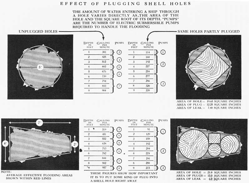
34-7. Flooding effect of holes. Figure 34-4 shows the flooding effect of unplugged holes and of the same holes after inserting the very simplest plugs. The volumes of flooding water are given in gallons and also in terms of the number of electric submersible pumps required to handle the flooding. It should be obvious that prompt plugging of holes is desirable to save the ship, to release pumps for use elsewhere, and to save wear and tear on those in use. Note that the pump capacities used are considerably under the rated capacities, but if the strainers are clogged with debris the actual capacities may be much less than the rated capacities.
34-8. Types of holes. Since many of the specific facts about battle damage are confidential, they may not be included in this volume. For such data consult Bureau of Ships war damage reports. However, attention is again directed to the fact that holes resulting from battle damage may be large or small, and that they vary greatly with respect to shape and whether jagged edges are turned in or out. Effecting repair is therefore a matter of adapting skill and knowledge to the particular needs that may exist.
PLUGGING AND PATCHING HOLES
34-9. Temporary repairs. The following suggestions for plugging and patching holes are designed for battle use. They are temporary repairs; things that can be done in action to keep the ship afloat and fighting. In most cases they do not call for elaborate tools or equipment gear that can be destroyed by the first enemy salvo. They involve principles that can be applied by using either prefabricated patches or other available materials that can be used to advantage.
No temporary patch will be perfectly watertight, but if the ingress of water can be reduced by only as much as 50%, it may be possible to control flooding
with the pumps and thus save the ship. All of these patches-all of the principles behind them--have been proved in battle. They have helped to bring ships and men home safely. Some of them have even enabled ships to remain at sea and in battle for months after the original damage was incurred.
It may be found that one type of patch does not seem to work well. Perhaps it is the wrong type for the particular leak that must be stopped, or it is not being employed properly. But do not be too hasty in condemning it; somebody else has used it and has found it effective.
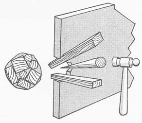
Figure 34-5. Combinations of conical and untapered plugs used to stop a hole.
34-10. Use of wooden plugs. There are two general methods of repairing a hole: put something into it or put something over it. In either case the effort is to reduce the area through which water can enter the ship, or through which it can pass from one compartment to another.
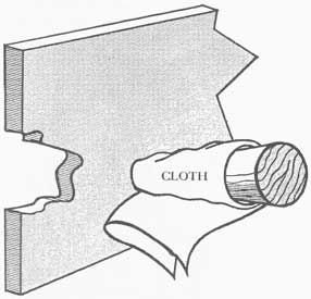
The simplest method of repairing a fairly small hole is to insert some kind of a plug. Plugs made of soft wood have been found rather effective under battle conditions, especially in holes not over 3 inches x 3 inches. They also have held up well in much larger holes.
Every ship should have a large assortment of conical, square-ended and wedge-shaped wooden plugs at each repair station. The plugs should not be painted, for unpainted soft wood absorbs water and holds better. Plugs should be stowed in canvas bags secured to the overhead.
Combinations of conical, square-ended and wedge-shaped plugs (see fig. 34-5) may be used to get
255
better conformation to the shape of the hole. It is best to wrap the plugs with lightweight cloth before inserting. The cloth will tend to keep the plugs in place, and also will fill some of the gaps between plugs. In most cases wooden plugs will not make
Figure 34-6. Plug wrapped with cloth prior to inserting in hole.
Figure 34-7. A rolled mattress used to plug a large hole.
a watertight fit, but by calking the remaining leaky area with rags, oakum and smaller wedges, the ingress of water can be greatly reduced. Square-ended plugs
hold better than conical plugs in holes in plating one-fourth inch or less in thickness.
Most wooden plugs are inserted from inside the ship. In such case repairmen have to contend with metal edges protruding inward. Plugs driven in from outside may not encounter so much interference, but outside plugs cannot be tended readily and do not hold well over extended periods of time. The use of a line secured to the inboard end of a plug by means of a screw eye (the line made fast to a stanchion) helps to overcome this difficulty. Whether to insert a plug from inside or outside the ship may depend upon several factors, such as access, flooding, or the presence of wreckage.
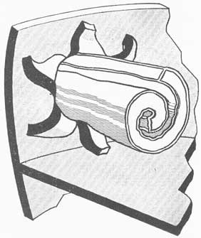
34-11. Pillows, mattresses, etc. as plugs. Pillows and mattresses have been rolled up and shoved into holes as indicated in figure 34-7. Occasionally they have been rolled around a wooden plug or a timber, to increase their size and to provide rigidity. Wrapping them in a blanket is sometimes effective. Such plugs cannot be relied upon, however, for they have a tendency to be torn out of the holes by waves.
A most effective plug was made by a ship after an enemy shell had torn an 8-inch x 10-inch hole in the side at the waterline. Unable to make repairs from inside because of wreckage, the ship made a built-up conical plug of cloth. The core was a piece of heavy line three feet long. An eye was spliced into each end of this core line, which was then wrapped with strips of blanket until a cone was built up, two inches in diameter at one end and two feet in diameter at the
Figure 34-8. A special plug for a large hole.
256
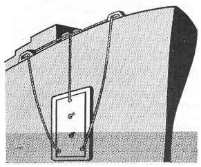
other end. The layers of cloth were held together and to the core line by stitching and serving. Lines were secured to the eyes in the core line, and by means of these lines the plug was lowered over the side and pulled into place as shown in figure 34-8. Such a
Figure 34-9. One type of prefabricated leak stopper.
plug has flexibility; it will become adapted to irregular shapes. Furthermore, it will absorb water and swell, which tends to make it more effective.
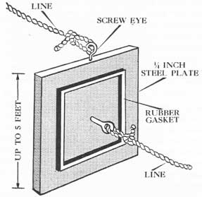
34-12. Prefabricated plate patches. One of the most useful prefabricated patches is made of a square piece of ten pound (quarter inch) steel plate (see fig. 34-9). On one side is a thick gasket placed near the edges, consisting of a thick tube of canvas stuffed with oakum or cloth. The gasket can be secured to the plate with machine screws, washers, and nuts, but the holes through the plate must be reamed so that the screws will not hold the plate away from the ship. The gasket can also be held in place with retainer strips.
At the center of the inner side weld a ring or an eyebolt for securing a line to hold the patch close to the shell of the ship. Another method often used is to drill a hole through the center of the plate, and to insert a line through the hole, with the outboard end knotted. The line used may be either wire or manila. Wire is stronger and it does not give easily; however, when coated with fuel oil it is very slippery and manila is therefore preferable.
These plates are made in various sizes up to five feet square, and in the larger sizes they are very heavy. Therefore, it is necessary to weld an eye at the top center for securing a handling line, which also gives
vertical support when the patch is in place. Similar eyes may be welded in place at the forward and after ends as securing guys.
The patch is lowered over the side by means of the handling and supporting line. Someone inside the ship reaches out through the shell hole, grasps the center line, and pulls the patch tight against the ship's side. The center line is then made fast to a stanchion.
Figure 34-10. A plate patch.
Plate patches (see fig. 34-10) have proved of great value in this war. One small ship returned from an action with eighty-four of them in use.
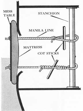
34-13. Improvised patches. Every ship carries a large amount of material from which patches can be improvised: mattresses, pillows, blankets, mess tables, planks, floor-plates, gratings, etc. One destroyer crew made an effective patch by placing a crew mattress over the shell hole outside the ship, backing it with a mess table, and holding it in place with two lines rove through two holes drilled through the patch. The inboard ends of the lines were secured to a stanchion, and were tightened by using cot sticks to make Spanish windlasses. Fore-and-aft guys also were provided to keep the patch in place against the action of waves. A comparable arrangement is shown in figure 34-11.
Another ship's force made a somewhat similar patch, using a floorplate, a mattress and a manila line. An eyebolt was welded to the plate to secure the line.
257
Repair parties should look about their areas to learn where they can readily find materials from which they can make patches.
Mattresses often are used to make patches over large holes. One such patch has been described. Sometimes, however, it is desirable to place the patch inside the ship as shown in figure 34-13, not only for
Figure 34-11. An improvised patch employing a mattress backed by a mess table.
Figure 34-12. Lines rigged for tending a large patch over the side.
accessibility, but to reduce the danger of having the patch knocked away by waves. For inside patches many experienced persons prefer innerspring mattresses, largely because they hold their shape better while being placed, and also because they are thicker and hence accommodate themselves better to protruding edges. It would be well to use at least one thickness of blanket as a facing for an innerspring mattress. Two thicknesses of crew mattresses generally will be more effective than a single mattress.
Figure 34-13. Improvised patch employing a mattress and placed inside the ship.
The mattresses should be backed with mess tables, steel plates, or wooden plates made of cleated planks, and they must be stoutly shored in place. Holes or cracks into which a mattress cannot be pushed may be stuffed with rags, oakum and wedges. In some cases these patches have not been satisfactory, but they have given good results over many shell holes and in replacing damaged watertight doors.
Feather pillows do not make effective patches or gaskets over a long period of time. When the feathers get wet, which is very soon, they tend to collect in a lump at one end of the ticking cover, and the patch
258
Figure 34-14. Diagram to show application of a box patch.
Figure 34-15. Types of hookbolts, and their use in applying a patch.
practically collapses. Furthermore, if the casing rips, the feathers come out and clog pump strainers badly. Kapok life jackets might be more effective in the long run. Folded blankets can be used in place of pillows.
34-14. Special types of patches. A variation of the plate patch is a circular plate eighteen inches or less in diameter, cut in two and so hinged that it may be folded and pushed through a hole from inside the ship. It is called a folding plate patch. The plate should be fitted with a gasket and also a line for securing it to the ship. A man in a shallow-water diving outfit can apply this type of patch over a submerged
hole without going outside the ship. The patch, however, is limited to use over relatively small holes because it has no vertical support to hold it in place.
A flexible plate patch has been suggested for use over curved surfaces such as the turn of the bilge. The plate is made of lightweight sheet metal reinforced with parallel strips of light angle iron welded in place about six or eight inches apart. The plate is provided with four eyes for securing lines, and it should have some kind of a soft gasket on the facing surface. It is, in effect, a rather stiff, metal collision mat.
A patch highly suitable for use over holes having
259
Figure 34-16. Materials used in assembling a folding T patch.
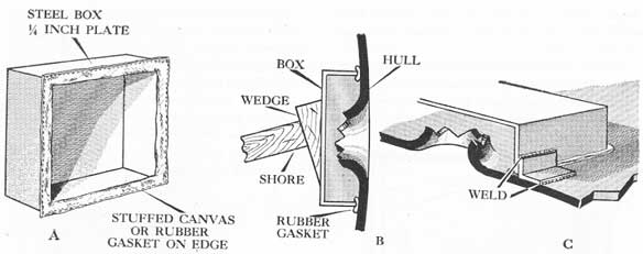
jagged edges protruding inward is a steel box (see fig. 34-14) in sizes up to eighteen inches square and six inches deep. The box is open at one end and has a gasket running along the facing edges. The gasket may be made of rubber or of canvas stuffed with oakum.
The box patch is put over a shell hole from inside the ship and is held in place with shoring. When the compartment is pumped dry, the box may be secured by welding angle clips between the box and the hull plating, after which the timbers can be removed for use elsewhere.
The box, however, cannot be fitted readily to irregular surfaces, hence adaptations to special circumstances sometimes are necessary. One variation is to stuff the box with pillows, or to lay pillows over the hole before applying the box. This has proved rather successful. Another possibility is to stuff rags and wedges into holes between the box and the rumpled hull. In the absence of ready-made steel boxes, similar patches can be made of planks. The advantage of a wooden box is that its edges can be shaped with a hatchet to fit closer to corrugations in plating.
An ordinary galvanized bucket (bucket patch) can be used in a variety of ways to stop leaks. It can be pushed into a hole bottom first to form a metal plug, or it can be stuffed with rags and put over a hole like the box patch previously described. It can be held in place by means of shores, or by using one of the hookbolts described below.
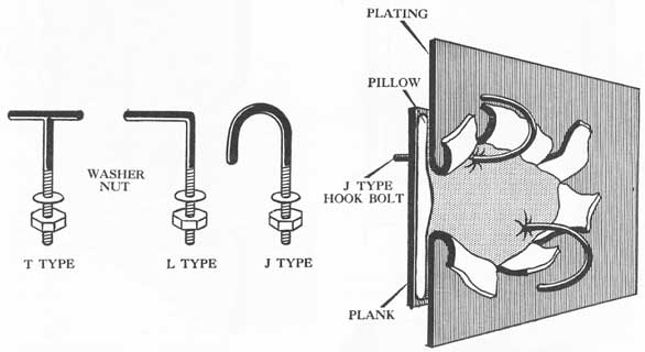
A hookbolt is a long bolt having the head end so shaped that the bolt can be hooked to plating through which it has been inserted. The common types are the T, the J and the L, so called because they resemble those letters (see fig. 34-15). The long shanks are threaded and provided with nuts and washers. Steel or wooden strongbacks are used with them; generally the latter. A hookbolt has no regular head.
The head end of the bolt is inserted through a hole, and the bolt is rotated or adjusted until it cannot be pulled back through the hole. A pad or gasket, backed by a plank or a strongback, is then slid over the bolt and the patch is secured in place by taking up on the nut. It is generally necessary to use these bolts in pairs. Hookbolts can be employed in combination with many of the patches previously mentioned, and
260
especially the folding plate, the box, and the bucket patches.
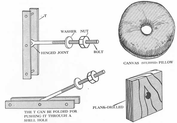
A variation of the hookbolt is the folding T, as shown in figure 34-16. It resembles the T hookbolt, but it has a hinge where the shank joins the cross-piece, so that it is much like the tumble toggle bolt. This bolt may be folded and inserted through a small hole; when pulled back, the cross-piece catches on the hull plating.
34-15. Welded patches. Many large holes in decks and bulkheads have been successfully repaired in battle areas by welding on steel plates. This method is not so safe, speedy and reliable as most uninitiated people think it to be, and it may be necessary to employ one of the temporary patches previously described while preparations are being made to weld on steel plates. Moreover, smaller vessels having only one welding machine may have that machine demolished by the first enemy salvo, and larger vessels may be without adequate power as a result of a large explosion.
If a flat steel plate is to be welded over a hole all protruding edges must be cut away. This cutting is done with an oxyacetylene torch or a pneumatic chisel, but neither of those tools can be used where gasoline or other explosive vapors are present or there will be a bad fire or explosion. Before using any flame or spark-producing repair equipment always test the air for the presence of explosive fumes, have a carbon-dioxide extinguisher at hand, and lead out a fire hose.
A great deal of work may often be saved in clearing a hole for repairs if the patch is applied to the side on which the projectile entered. Therefore, if a bomb penetrates a deck put the patch on the upper side-not on the lower side. A patch may be applied to the outside of the hull by lowering a welder and his gear over the side in a boatswain's chair, but this would be very difficult if the ship were making any speed in a rough sea. For this and other reasons, early welded patches generally are confined to those that can be applied on decks and interior bulkheads; others are put in place when the ship has had a chance to withdraw from the battle area.
A steel plate can be held lightly in place by tack welding, after which the welder can go around the plate with a solid bead, not only to fasten it securely, but also to stop all the cracks. If the plate is large, it must be reinforced with welded stiffeners on the back and possibly with shoring to prevent too much motion as the ship works in a seaway. If this precaution is not observed the welding may crack. In one case the patch opened wide and acted as a scoop, so
that the ship actually was in worse condition than it was before the plate was installed.
MISCELLANEOUS LEAKS
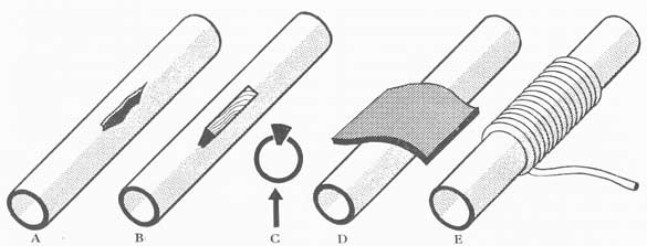
34-16. Cracks. A fairly common type of leak is a crack in a steel plate. If the leak is in a flat surface away from frames and other interferences, it can
Figure 34-17. One method of installing a folding T patch.
Figure 34-18. One type of patch to stop leakage through a crack.
261
generally be stopped by scraping the surface smooth and applying a patch of sheet packing backed by a board as shown in figure 34-18. These materials can be held in place by shoring.
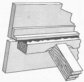
Figure 34-19. Crack under a welded frame stopped by bracing a timber over oakum.
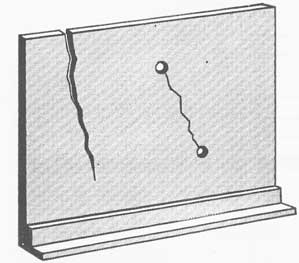
Figure 34-20. Holes may be drilled at the ends of a crack and plugged to stop extension.
If the crack is adjacent to a frame it may be necessary to use oakum held in place by the corner of a timber as shown in figure 34-19. Advantage should be taken of adjacent framing to use clamps for securing the stopper.
Upon re-inspecting a crack it may be found that it has increased in length. The plating is being torn like paper. In such case drill 3/4-inch holes at the extreme
ends of the crack, as shown in figure 34-20, and plug the holes. If there is time, weld a plate over the crack.
It generally is not advisable to drive wedges into cracks in thin plating, and especially not hardwood wedges, for they tend to open the cracks. Marline, oakum and rags can often be used as effective calking materials.
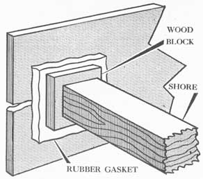
34-17. Torn seams. Among the most difficult holes to plug are torn seams or loose bounding bars where deck and bulkhead plates are joined. Rags, oakum, marline, soft wood wedges, shingles, lead strips, lead wool, various plastics and even metal calking have been used to plug such leaks as indicated in figure 34-21. These materials are applied on the unflooded side, but because the plates work the cracks open and close continually. Concrete held in place by a wooden cofferdam has been used effectively in stopping several such leaks. It is not advisable to weld leaky riveted seams for the intense heat will cause adjacent rivets to leak.
Doors and hatches are often sprung by blast, especially if they were not properly secured. Sometimes the closure can be made tight with shoring. If small spaces are open between the closure and the knife edge, they can be treated as cracks.
Armored hatches present a peculiar problem, especially when the surrounding decks are warped. Sometimes the best remedy is to cut the hinges, after which the hatch will fall back into its proper place.
Stuffing tubes around electric cables and reach rods leak all too frequently, either because they were not properly packed or because the packing has hardened with age. Sometimes it will suffice to tighten up on the packing nut if it is accessible in a large nest of wires. Marline, oakum and very small wedges have been used effectively. The best remedy is prevention: see that they are properly packed, and check with periodic air tests.
In some cases leaky shaft glands have been repaired by tightening up on the nuts. In others, the studs have been broken and it was necessary to shore the whole gland back into place, preferably with welded braces. In one instance the leak was so bad that the ship's force made a box patch in two sections, secured it around the shaft, and welded it over the gland. In effect, the ship had a new gland.
Leaky rivets are not easy to repair. Frequently they are pulled through plating but remain so close that wooden plugs cannot be driven home. Slugs cut from sheet lead have been used to good advantage, as have lead wires, marline and red lead. Sometimes caulking is effective.
262
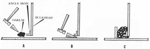
Figure 34-21. A, stopping a leak under an angle iron; B, if a wedge is to be used it must be of soft wood so that the joint will not be opened; C, stopping a joint leak with cement.
Figure 34-22. Cofferdam to enable opening of door into a partially flooded compartment.
COFFER DAMS
34-18. Cofferdams as leak stoppers. A method often employed in stopping large holes involves the use of cofferdams (see figs. 34-22 and 34-23). A cofferdam in this case, is a large wall or fence built around the damaged area. The steel box previously described is really a prefabricated cofferdam of limited size. For use during and immediately after a battle, cofferdams are installed inside the ship. Outside cofferdams often are used in salvage operations.
A cofferdam may be built up of steel plates or heavy planks (preferably tongue-and-groove), either
directly supported by frames and stanchions, or held securely in place by shores. When constructed it may be partially or completely flooded. If it were possible to build a cofferdam thoroughly watertight, as in the case of welding plates together and to the ship no further steps would be necessary.
However, conditions seldom permit construction of a watertight box. A strong retaining wall should therefore be built around the hole and the box left open at the top. Mattresses, pillows, bales of waste, clothing and similar items are dropped into the box until it is full. Since most of these materials will float it is
263
necessary to weight them to get them down to the bottom of the cofferdam. When the box is full, keep the stuffing materials down by means of iron bars or shores. A cover may be put on the top, if desired. This arrangement is more reliable than shoring, although the whole structure should be strengthened by shores all around. The fibrous stuffing materials will act as calking agents to exclude water. Cofferdams may be built to cover holes in either vertical or horizontal plating.
It is possible that the hole will be so large that even mattresses or bales of rags would fall out through the side of the ship. This can be prevented by installing a grating of crossed pipes, timbers or angle irons Over the hole before attempting to stuff the box. One repair gang made an effective mat merely by laying a sheet of expanded metal over the hole.
Figure 34-23. Top view of cofferdam shown in figure 34-22.
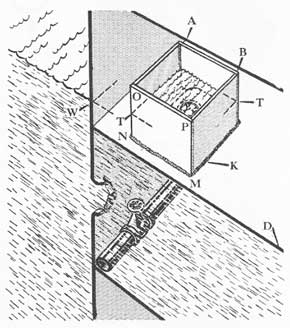
34-19. Access via cofferdams. Cofferdams may also be built around hatches, trunks and doors when it is necessary to go from a dry compartment to a flooded compartment (see fig. 34-24), or vice versa. Above all do not permit the flooding to spread.
Suppose, for example, that it is desired to enter a lower compartment which is open to the sea and completely flooded. The outside water level is two feet above the deck which bounds the top of the compartment. Obviously, if a hatch or scuttle is opened, the upper compartment will be flooded. However, if a tight cofferdam is built around the hatch and extended upward about two feet above the outside water
level, it will be possible to open the scuttle with safety. A man in a shallow-water diving outfit can then go below to operate valves or to plug small leaks.
The same cofferdam could be used if the upper deck were flooded and it was necessary to free men who were trapped in a dry compartment below. The cofferdam can be extended upward to higher deck levels if necessary, and escape scuttles can be cut with an acetylene torch.
Figure 34-24. Cofferdam permitting access from a dry to a flooded compartment below.
If steel plate and a welding machine are available, it is possible to make a most effective cofferdam. Make sure that it is securely welded at the corners and to the deck, and if there is not time to make a tight weld all around, caulk the cracks with oakum. Cross-bracing or shoring is necessary if the water will be deep in or around the cofferdam.
For a wooden cofferdam, use planks, preferably cut tongue-and-groove. Install cleats across the boards of each side, and lock the corners securely with cross nailing or by means of metal strips. Press the cofferdam down tightly to the deck with adequate shores from above, and calk all cracks and seams with oakum or undershirts. Provide shoring as necessary to support the walls against water pressure. A portable pump suction may have to be put inside the cofferdam to remove leakage.
The same principles may be applied to a cofferdam
264
Figure 34-25. One type of soft patch. A, ruptured, pipe; B and C, soft wooden plug driven in; D, sheet rubber or sheet packing applied (should overlap ends of hole by two inches); E, bound with marline or wire.
over a watertight door when it is desired to go from a flooded compartment to a dry one, or vice versa. The cofferdam must be high enough to extend well above the outside water level, and also large enough to permit opening of the door.
It cannot be too strongly emphasized that when using a cofferdam as a means of access between flooded. and non-flooded areas, the cofferdam must be strongly built and firmly secured. In such cases one is almost invariably gambling with the safety of the ship: there is much to be gained if the plan succeeds, and possibly a ship to be lost if the cofferdam slips or collapses. However, cofferdams have proved their worth; they have saved ships and many lives.
STRENGTH MEMBERS
34-20. Damaged strength members. Beams, frames, decks and some bulkheads are strength members of the hull structure and if they break or become weakened the hull may collapse and the ship break in two and sink. A small vessel ordinarily does not have the necessary equipment to weld on heavy rails or angle irons about the ship to give additional support, but some help can be afforded by shifting weights to reduce the strain, and also by shoring.
Beams and frames can be patched or strengthened by bolting or welding doubling plates or bars along the webs. The velocity-power stud driver may be useful for this purpose.
30-21. Reinforcing supports. Supports for heavy equipment, such as 20 mm. guns, may be pushed back into place with screw jacks and shoring, and later secured with stanchions made of heavy pipe welded in place. Chainfalls and heavy wires, possibly fitted
with turnbuckles, may be found useful in pulling plating and equipment back to their original positions. Supports under dislocated machinery and guns often must be carried down several decks, because a single deck may not have the strength to support all of the weight. It may be necessary to install successive supports clear down to the bottom frames. In shoring heavy weights, put the butt of the shore on a solid frame, or spread the weight between two or three frames by means of sholes and cross-timbers.
Some strength can be restored to cracked, fractured or weakened supports under machinery by welding on side plates.
PIPE LINES
34-22. Soft patches. Before undertaking repairs on any pipe it may be necessary to remove pressure from the line, and to provide the same service by some other means.
Small holes or cracks in low-pressure (150 pounds) piping often can be repaired by using what are known as soft patches. One type of soft patch is shown in figure 34-25. When possible, the area of the hole should first be reduced by driving in softwood wedges. They should not be driven in too far, or they will retard the flow of fluids. The wedges should be trimmed flush with the outside of the pipe, after which the area should be covered with a strap of sheet or rubber packing tightly held in place by two layers of marline or wire. The packing should extend about two inches on either side of the hole.
The soft patch can be modified or improved to suit immediate conditions. It often is advisable to have a curved plate of lightweight sheet metal between the
265
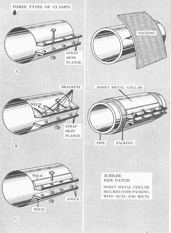
Figure 34-26. Jubilee pipe patch; three types of clamps and method of application.
266
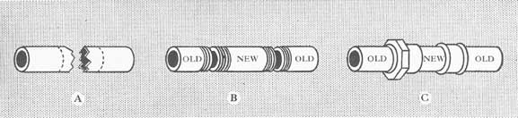
Figure 34-27. Method followed in renewing a section of damaged pipe. A, pipe ends cut off at dotted lines and threaded; B, new section of pipe (threaded) inserted; C, union and coupling used to join new and old sections.
packing and the binding. A coat of white or red lead on the face of the packing is also useful. Marline and oakum have been used successfully as a calking material in cracks. In many cases, as on sharp curves, it is not possible to use sheet packing, but combinations of wedges, marline and various plastics will often make effective patches.
The patches described above are not recommended for high-pressure steam lines, but they are satisfactory for low-pressure steam lines. Rubber packing will melt and make an offensive odor, which may be confused with poisonous gases, but it will vulcanize and make a tight patch. In one case a 150-pound steam line was repaired by wrapping the crack with marline dipped in red lead putty. A paste of litharge and glycerine can also be used. After making such a repair, cover the affected area with a burlap bag to reduce the danger of injury to personnel caused by hot drops.
34-23. Other types of patches. Soft patches cannot be recommended for gasoline lines, because the slightest leak would create a tremendous fire hazard. It would be far safer to renew the damaged section.
Many jagged holes have been stopped by inserting cloth-covered wooden plugs. Sometimes combinations of plugs may be used. Set up on the plugs with a hammer, and try to secure them in place with clamps or wires; otherwise, they may work out under pressure. If the hole is not too large it may be drilled and tapped for inserting a screw plug.
C-Clamps and thumb clamps may be used to hold plugs or patches in place. For example, a block of soft wood may be rough-shaped to fit over a damaged area in a pipe, and the pad may be held in place tightly with two thumb clamps. Care must be taken to re-inspect patches held in place by clamps for they have a tendency to work loose under shock or vibration.
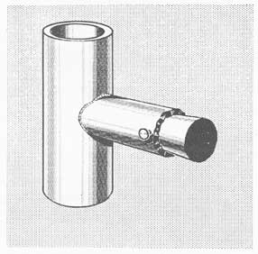
The Jubilee pipe patch shown in figure 34-26 is
a modification of a commercial hose clamp. It consists of a piece of sheet metal which is rolled into a cylinder and so shaped at the gap that the two ends are really flanges. These flanges can be reinforced by welding on strips of strap iron, after which the two flanges are drilled to take from three to five bolts. It is advisable to weld small braces from the flange to the back of the patch to keep the flange faces more or less parallel under pressure.
The sheet metal in the body of the patch should be as heavy and strong as possible, but it should be capable of being sprung or bent so that the gap will go over the pipe to be repaired. /V sheet of packing is first put over the hole, extending well on either side of it. The Jubilee clamp is then sprung open and clamped over the packing. When the bolts are tightened this patch will easily hold. 100 pounds pressure. Every damage-control locker should contain several of these home-made patches in assorted sizes, because each patch fits only one size of pipe.
Light calking with hammer and chisel has sometimes been used to close small crack leaks, especially adjacent to flanges. However, there is always a danger of opening the crack even wider.
Welding, brazing and silver soldering can be used to repair leaks, especially at the joints between pipe and flanges. However, these methods are slow, are not reliable in the hands of unskilled personnel, and may lead to fires and explosions. Therefore, their utility in actual battle is limited.
34-24. Renewing pipe sections. If a pipe has been badly holed or ruptured, patching may not suffice, and it may be necessary to renew a section. It would be advisable, therefore, to carry on board spare sections of the smaller sizes of important pipe. In an emergency, it may be possible to remove a section from an unimportant system to use where it is needed more.
If the original pipe was fitted with screw flanges,
267
remove the entire damaged section, cut screw threads on the new piece, screw the flanges on to the new piece, and install it. The flanges are bolted together. To renew only the damaged part of a small pipe, cut out the damaged area with hacksaws, and cut a fresh piece of pipe almost the same length as the gap, as shown in figure 34-27. If the pipe is small, it may be joined by means of a velocity-power pipe bonding press. If you do not have such a tool, cut screw threads on all exposed ends of pipe, and make up the joints by using pipe unions and couplings. In the latter case, cut the filler piece short enough to permit inserting the pipe fittings. White lead may be used on screw threads to get a tighter joint.
Figure 34-28. Wooden plug used to blank off a low-pressure pipe line.
The foregoing methods take time, and if service is required in a hurry, unions may be improvised similar to the soft patches previously described. However, if the joints are not held together they may be pushed apart by pressure reaction. It is therefore advisable to force the joints together by means of lines, shores or wedges.
34-25. Special clamping devices and couplings. Nearly all large vessels have now been provided with a hand clamping device, together with the necessary metal straps and clamps. Complete directions for its use will be found in the box. It is useful in securing soft patches and in securing hoses to couplings and pipe. Like any other tool, it is no better than the man who operates it, and 'since there are certain
"tricks" to be learned in connection with this equipment every ship should have spare bands and clamps so that men may be trained to use them.
34-26. Blanking pipe lines. Ruptured pipe lines often are a menace in that they cannot be isolated
Figure 34-29. Pipe cap used to blank off low-pressure pipe line.
readily and still have the system perform a vital function.
Low-pressure pipe lines can often be blanked off by driving in wooden plugs covered with cloth as shown in figure 34-28. Unsupported, these plugs have a tendency to back out. Adequate support generally can be provided by using shores or jacks, or by drilling a hole through the pipe and pinning the plug in place with a nail. For frayed ends of pipe cut by fragments combinations of plugs may be desirable.
Figure 34-30. Blank flange used to blank off pipe line.
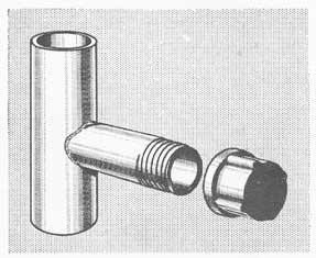
When the damaged pipe is joined by screw fittings, it is a simple matter to unscrew the damaged part and to stop the flow of fluid by means of a pipe cap or pipe plug (see fig. 34-29).
268
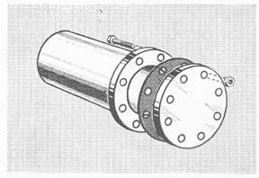
Where the joints are made up by means of flanges, blank flanges may be used (see fig. 34-30). A blank flange is a flat plate of heavy metal, circular in shape, and provided with standard bolt holes. A gasket of sheet packing normally is used with most low-pressure flanges, and special gaskets on steam lines.
Figure 34-31. Flange fitting for adapting hose connection to a flanged pipe connection.
Whenever possible such gaskets should be used, even when making rapid repairs during battle. Otherwise there will be excessive leakage.
In order to save time and to have everything ready for use, all flanges in repair lockers should be made up with studs, nuts and gaskets attached to them.
Figure 34-32. C-clamps may be used to join flanges that do not mate.
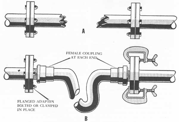
Figure 34-33. Hose jumper to restore service to a ruptured pipe line.
269
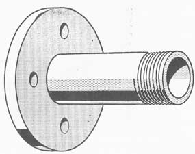
One type of flange resembles a blank flange, except that the center is cut away and the hole is surrounded by a short pipe having screw threads. It is called an adapter (see fig. 34-31 ). The flange may be bolted to any similar flange on a pipe line, and a hose may be coupled to the pipe threads, thus permitting a jumper to be used.
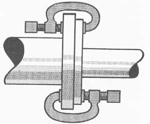
For each size of pipe in the U. S. Navy the flanges are standard. However, a case may arise in which it is desirable to connect flanges of different sizes of pipe. The flanges cannot be bolted together because the bolt holes do not line up. The difficulty may be met by inserting a gasket and holding the two flanges together with heavy C-clamps as shown in figure 34-32. Four such clamps are desirable, even on fire mains.
Figure 34-34. A single conductor may be made up of many fine wires in contact with one another.
ELECTRIC WIRING
34-27. Conductors and cables. Almost any kind of explosive or projectile hit will cause extensive damage to electric wiring. Wires may be cut, grounded, shorted or completely destroyed, leaving the ship without power on many important lighting, fire-control, communication, ship-control and power circuits.
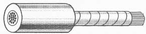
Electricity is carried from generators to machinery by means of wires called conductors. A conductor is a group of small wires bunched together, but not
Figure 34-35. Diagram of multiconductor cable.
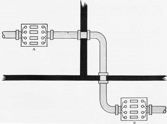
Figure 34-36. It may he necessary to rig a cable from box A to box 13 in case the original installation is damaged.
270
insulated from each other, so that they are the same electrically as a single wire (see fig. 34-34). Each conductor is covered with insulating material. The outside covering of each insulated conductor is of a distinct color pattern; a different pattern for each conductor. One may be solid green, another yellow and black, and a third may be red and blue.
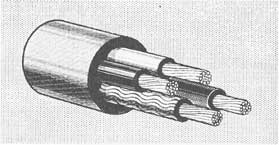
A group of conductors held together and enclosed by an outer casing (cable sheath) is called a multiconductor cable (see fig. 34-35). The conductors are insulated from each other as previously described. The whole group may be further enclosed by various materials, and may also be covered with a wire braid. These additional features are to protect the conductors from fire, heat, water and rough handling.
34-28. Use of jumpers. Short ruptures in conductors and cables frequently are repaired by inserting pieces of new cable, called jumpers. It is much the same as running a hose jumper between two fire plugs to bridge a damaged section of the fire main. Most ships carry assorted jumpers up to ten feet long at each repair station, or reels of cable from which jumpers may be cut.
Before beginning repairs on any damaged electric circuit it is almost always necessary to remove power from the line, not only to protect the workmen from shock, but also to prevent fires and explosions. This may be done by opening switches, tripping circuit breakers, or removing fuses.
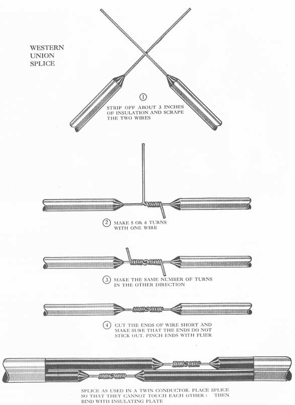
When small single conductors are cut the damage may be repaired temporarily by skinning back the insulation on both the jumper and the original conductor, and splicing a jumper across the break. Clean the wires. Scraping them with a knife blade will generally suffice. Twist and lock the conductors together in such a manner that they cannot be pulled apart, making sure to have a good metal-to-metal contact. Then wrap the exposed metal joint tightly with tape.
The procedure for inserting jumpers in large conductors is much the same as in the case of small conductors, except that the larger size of the wire requires the use of different methods of securing the conductors to each other. The velocity-power press (steel cable) can be used. In an emergency, almost any type of cable clamp will suffice. These joints, too, must be carefully bound with insulating tape.
34-29. Identification of conductors. As previously stated, each conductor is covered with an insulating material of a different color combination. These color combinations may be used to identify conductors, so
that the wires may be joined correctly in a short time. This is very important when there are twenty conductors in a cable and you have to bridge a gap in ten of them to restore power on a gyrocompass.
If wires were connected at random, the result would be a condition of chaos. Vital equipment would receive no power and unimportant motors might operate backward. However, if red is connected to red, black with green tracer to black with green tracer, and so on, the circuits will be restored correctly, and all equipment will work properly.
If a repairman could not identify the color markings on conductors because of burning or discoloration by fuel oil he would have to cut back the outside armor and insulation until he could find undamaged color markings, or he could resort to a method of identification used before the present system of marking was adopted. It is called "ringing through."
Men with sound-powered telephones station themselves at each end of the damaged cable. They ground one end of their phones to the ship's structure, or to the metal armor around the cable, and one man secures the other end of his telephone to the first conductor he desires to have repaired. The other man uses his second wire to hunt for the proper conductor, and by touching each conductor in turn, he can soon locate the one that must be repaired. This telephone circuit can also be used for exchange of information and orders.
34-30. Insulation. Each individual joint made by joining conductors must be thoroughly insulated with tape, and when several such unions are made in a cable repair, the whole area should be securely wrapped with waterproof tape to avoid contact with salt water or the ship's structure. Do not permit the cables to lie on deck; if necessary, trice them up to the overhead.
34-31. Long cables. When damage to a cable is extensive, it may be necessary to renew a complete section between junction boxes, or between distribution boards and boxes. Long cables rather than jumpers are required.
Sometimes the old cable is pulled out through stuffing tubes and a new cable is installed. Care must he taken to plug the tubes temporarily to preserve watertight integrity. In other cases the new cable is run by the most rapid means available, which may involve taking it through doors and hatches. Every care should be taken to avoid impairing watertight integrity any more than is absolutely necessary.
271
Figure 34-37. The Western Union splice. To finish the job insulating tape and friction tape are used.
272
Figure 34-38. Mockup used in training repair personnel to plug holes.
The job of running these long cables should be under the direction of experienced electrician's mates who are familiar with the electric circuits in their areas. However, all repairmen should know that each conductor is identified by a number on a metal tag where the conductor is secured in a junction box, and also by colored, metal, numbered tags where the cable goes through a deck or a bulkhead.
In order to avoid wasting time on repairs of unimportant circuits, to the detriment of repairs on vital circuits, many cables bear colored tags at points where they pass through decks and bulkheads.
Color
Meaning
Red
vital
-light and power
Yellow
semi-vital
-light and power
Blue
vital
-I.C. and fire control
Green
semi-vital
-I.C. and fire control
Hot circuits are those carrying electric current. Because 440-volt current is extremely dangerous, only the most experienced electrician's mates should be permitted to work on hot circuits, and then only when the workman has been adequately insulated. In general, it would be safer to isolate damaged circuits before beginning repairs.
273
Figure 34-39. Mockup used in training repair personnel to patch ruptured pipe lines.
TRAINING
34-32. Type of training needed. It is not sufficient that men merely read about how to make repairs or study pictures of equipment and methods. Nor is it enough that they have all the tools authorized by the allowance list, or that they make all the prefabricated patches and tools suggested in this book. All damage-control personnel must know how to apply the principles and materials in the most effective way. That knowledge can be gained by education, training and actual practice.
As indicated in previous discussions, about the most important equipment a damage-control man can have is a thorough knowledge of his ship. He must know his own area and also the adjacent areas, in case he has to go there to make repairs after another repair party has been wiped out. Therefore, it is mandatory to exchange a few men between repair parties from time to time, so that they may train and drill in adjacent areas.
A good damage-control man is a jack of all trades. He should learn to do any job that may be required
of any other man in his party. Electrician's mates can learn to shore, shipfitters to hook up the casualty power system, and carpenter's mates to patch pipe lines. All hands can learn how to fight fires and to apply first aid. A man may not become an expert in every field, but he can at least become a capable helper, and in an emergency his general ability may be just what is needed to save the ship.
Heretofore, training in making battle repairs on board ship has generally been limited by circumstances. Occasionally the maintenance gang or the engineers had to repair a leaky pipe, or the electrician's mates had to renew a small cable. But there seldom was a chance for the average member of a repair party to do any real shoring, to stop a leak in the hull, or to gain experience in any part of damage control outside his own specialty. Training was therefore weak, because the most imaginative and energetic organization had to pretend that damage had occurred. There was seldom any way to learn whether or not the repairs made would have been effective under the pressure and vibration incident to battle conditions. The test came when actual damage was sustained, and we may
274
be thankful that even our elementary and mock training has saved ships and lives.
How many more lives and ships might have been saved had every repairman been trained to use his head, his hand and his equipment to the best advantage-if he had known all the little tricks of using this patch or that, and just what result he could expect from each?
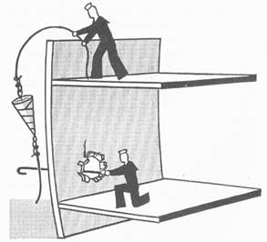
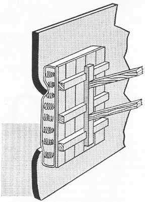
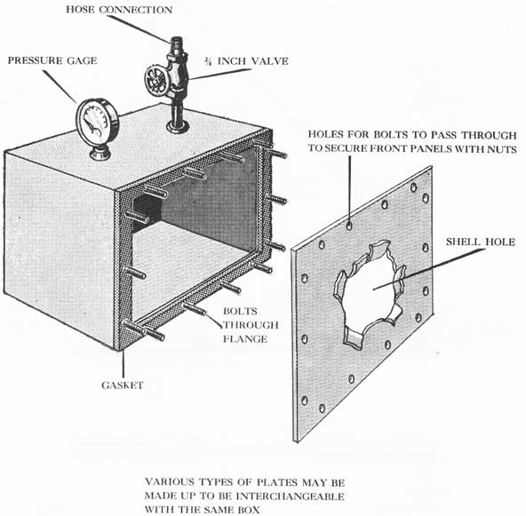
34-33. Use of training mockups. Various mockups can be used in training men to make repairs. These mockups can be made on board ship. Figure 34-38, for example, shows a steel box used for training repair
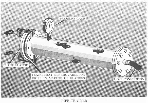
personnel to plug holes in plating. Many types of patches can be used, and the box put under water pressure to test the quality of the workmanship. Figure 34-39 shows a similar mockup for practice in repairing pipe lines.
While these mockups represent circumstances far short of real battle damage, they will give the men good practice in using their hands, and an opportunity to study better methods and short cuts in making repairs. The use of water pressure not only makes the instruction more interesting, but shows even the best man that he needs practice if he is to do a good job.
275
CHAPTER XXXV
REPAIR PARTY EQUIPMENT
35-1. Allowance lists. The ship's allowance lists, including those having to do with damage-control equipment, are prepared by the Bureau of Ships and are distributed to the vessels and the supply activities requiring them. These lists serve as a guide for the supply officer in outfitting with the tools and equipment required to be on board to operate and to fight the ship. The damage control officer must insure that he has a full allowance of tools and equipment on board at all times.
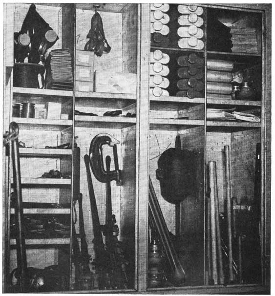
A full allowance of tools and equipment can be maintained in repair lockers only by frequent inspections and careful inventories. Tools must actually be in their assigned stowages and in good condition. A check-off list of required tools should be kept in each repair locker, and an officer or a leading petty officer should be assigned to inventory the lockers weekly. Missing or inoperative equipment must be replaced immediately.
In many cases the allowance list will indicate for which repair locker certain specified tools and equipment are intended. When this is not the case, the damage control officer must use his own discretion in
the distribution of equipment, keeping in mind the special uses of various tools in handling battle damage. Tools and equipment must be so dispersed that all of one type cannot be destroyed by any single hit. It may therefore be advisable to divide the gear on any station between two or more lockers widely separated within the area. Tools must be provided for each repair locker in keeping with the area the locker must serve. Consideration must also be given of the machinery within the area, and to any unusual casualties which may occur there.
The section of the allowance list devoted to damage-control equipment does not include a large number and variety of tools and stores that must also be provided at repair stations. Some of these items are claw hammers, wrenches, sheet packing, binding wire, marline, pliers, screwdrivers, hand saws, hacksaws, fuses, fuse pullers, light bulbs, chisels, nails, bolts, nuts, washers, blank flanges, sheet lead, and manila line.
35-2. Tool markings. All damage-control tools should be marked with distinctive colors so that they can be positively identified as damage-control gear. Tools designated to be stowed at repair stations can
Figure 35-1. Two types of emergency ladders.
276
Figure 35-A. Tools and equipment in repair lockers must be checked by inspection and inventory.
be marked with red and yellow stripes, possibly with the addition of a numeral indicating in which locker the tool belongs. Tools that are to be on bulkheads or hatches about the ship, such as those normally used for operating fittings, may be marked with yellow and green stripes. These marks will reduce the loss of tools through carelessness, and the yellow stripes will aid in locating tools when lighting is poor.
35-3. Improvised tools. Many useful tools can be improvised by the ship's force or by a tender. The
number and types thereof are limited only by the ingenuity of the persons concerned. Here are a few suggestions:
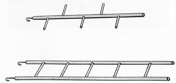
1. A portable ladder made of pipe as shown in figure 35-1, with a hook or hooks on one end, for use in ascending or descending through hatches where ladders have been destroyed. There should be one of these in each repair locker.
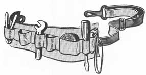
2. A wide canvas belt fitted with loops for carrying small tools as shown in figure 35-2. This leaves the
277
wearer's hands free for work, and keeps the tools within reach of the workman. Otherwise, tools may be dropped at random in a partially flooded
Figure 35-2. Repairman's belt.
compartment, and critical time lost in searching for them. Have one of these for each two men in the repair party.
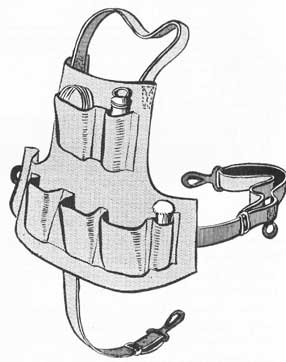
3. A canvas apron (see figure 35-3) with loops and pockets may be used in place of the belt. A similar apron may be used for carrying rescue breathing apparatus canisters and tending lines.
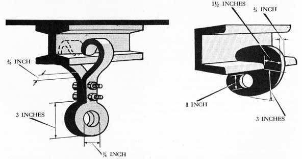
4. Beam clamps of suitable size and shape are necessary when using chainfalls and jiggers. Have two of these (see figure 35-4) for each chainfall in the repair locker.
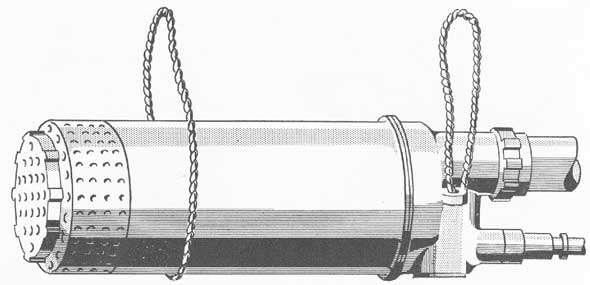
5. If a regular carrier is not provided for submersible pumps, slings made fast at each end of the pump assist greatly in carrying it through the ship (see figure 35-5). Two men act as bearers, placing their arms
Figure 35-3. Repairman's apron.
Figure 35-4. Two types of beam clamps.
278
Figure 35-5. Slings for carrying a portable submersible pump.
through the loops and carrying the pump horizontally between them, the shoulders supporting the weight of the pump. Have a suitable carrying arrangement for each submersible pump.
6. The strainer baskets for portable submersible pumps described in Chapter XXIX may be made collapsible for easy stowage (see fig. 35-6). Provide each basket with a bale made of white line or marline for lashing the basket to the discharge hose. This permits lowering the pump and basket together into a flooded space. Have one of these baskets for each pump plus at least one spare at each station. The spares are for interchanging when it becomes necessary to clean a strainer.
7. A shoring chest of the type pictured and described in Chapter XXXVI should be in the locker of each main repair station. A shoring chest is also shown in figure 35-B.
8. A universal wrench as shown in figure 35-7 provides a combination of several units which would be of value to men working in a damaged area. The wrench may be varied to suit the type of ship on which it will be used. Make two of these for each main repair station.
35-4. Small tool storage. Small tools in the repair locker present a problem in stowage. When such tools as pliers, screwdrivers and wrenches are stowed on shelves or in bins they are soon covered with larger tools. Then when they are needed, it is
necessary to institute a search for them. Further, when there is only a hit-and-miss system of stowage it is difficult to make a careful inventory. "A place for everything and everything in its place" is a slogan that should apply to every repair locker. Figure 35-8 shows a suggested stowage for small tools within the locker. It consists of a heavy fire-proofed canvas backing, provided with loops for holding small tools. When in use it may be suspended from a deck beam, so that every tool contained is plainly visible. Missing items are obvious. When the locker is secured, the tool holder should be rolled up and padlocked. If it is fitted with a pair of strap handles the entire roll may be quickly and easily transported to the scene of operations.
35-5. Stowage of large tools. Large tools should be so arranged in the repair locker that they will be easily accessible when needed. This may be done by the use of bulkhead clips for tools such as crow bars, mauls, axes, and submersible pumps. Tools and equipment stowed in this manner must be securely fastened in place, to prevent their becoming missile hazards by being thrown around as a result of a nearby explosion. They must be secured against both lateral and vertical explosive forces.
It is advisable to paint tool outlines on locker bulkheads where tools are to be secured in clips. Use black paint on white bulkheads. Missing tools will be obvious at once, because of the absence of the red and yellow stripes.
279
Figure 35-6. Collapsible strainer basket for use with portable submersible pump. Make it large, but not too large to pass through scuttles.
Figure 35-7. Special universal wrench. A, socket for nuts on hatch dogs; B, lug to fit socket on flush deck type of remote-control gear; C, spade for flush deck armored hatches, etc.; D, lug to fit socket on deck drains in heads and wash-rooms; E, socket to fit hatch nuts not covered by A; F, body of 1-inch iron pipe; G, 2 1/2-inch hose spanner; H, 1 1/2-inch hose spanner; J, socket to fit nut on escape scuttle handwheel; K, pipe left open at both ends for drop bolts.
Small items such as nails, nuts, bolts, washers, and fuses should be secured in metal boxes or in canvas bags to reduce their splinter hazard. The containers should be clearly labeled as to the kind and quantity of their contents.
35-6. Protecting the repairman. Every member of a repair party must be fully clothed for protection against flash burns. A full suit of dungarees is the minimum acceptable. Shirts must be buttoned up to the neck and cuffs buttoned at the wrists. Provide each man in a repair party with a steel helmet.
Other items for personnel protection may be made on board ship. Among them are:
280
Figure 35-8. Canvas roll assembly for stowing and transporting small tools.
281
Figure 35-B. A shoring chest.
1. Slippers made of sheet asbestos packing, which may be worn over the shoes of men working on hot steel decks.
2. Shin guards similar to those worn by baseball players. These protect the legs of men working around jagged edges of steel plating in a damaged area. The shin guards may be made of light sheet metal.
Every man in a properly equipped repair party should be provided with:
1. A flashlight on a lanyard.
2. A knife (sheathed or on a lanyard).
3. Asbestos gloves for handling hot steel plates, or leather gloves for handling jagged plates.