|
PART VI
CCM MARK 1
601. GENERAL.
(a) The Combined Cipher Machine Mark 1 (CSP 1600) is a device which
converts the ECM
Mark 2 to the cryptographic equivalent of the CCM. The CCM Mark 1 is a unit
similar to the
ECM Mark 2 Cipher Unit. All alterations and modifications are contained
within the unit and no
change in the ECM Mark 2 is necessary except to insert CSP 1600 into the
machine in place of
CSP 887.
|
NOTE: When not in use, CSP 1600 is to be kept in the special metal box
provided with each unit
It shall be securely fastened with the four thumb screws.
|
602. CODE WHEELS.
(a) The Code Wheels used with CSP 1600 are similar to those used with the
ECM Mark 2 except
that cam-contours have been cut at irregular intervals on the periphery of
each face for the
purpose of actuating the Stepping Magnet Contacts, and the cam lobes have
been ground off.
603. DESCRIPTION.
(a) The unit is so constructed that only five Code Wheels of the set are
used at a time. These Code
Wheels (together with the connections established through the plunger
contacts) form the
Alphabet Maze.
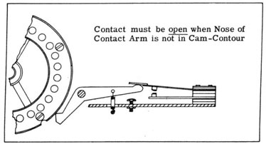
(b) Four Stepping Magnet Contact Operating Arms and associated Contacts are
included in the
unit Their function is to control the stepping of the Code Wheels. Each
Contact Operating Arm in
so positioned that the nose of the Contact Arm rides the periphery of a
Code Wheel. As the Code
Wheel is turned, the nose drops into a cam-contour thus closing the
contact. When the nose
rides the periphery of a Code Wheel the contact is held open. The Code
Wheel controlled by this
contact will step in accordance with the cam-contours on the controlling
Code Wheel
|
NOTE: IT IS A REQUIREMENT THAT THE STEPPING CONTACTS BE CAREFULLY ADJUSTED
SO THAT
THE CONTACT WILL BE POSITIVELY "OPENED" OR "CLOSED", DEPENDING UPON THE
POSITION
OF THE CAM-CONTOURS OF THE CODE WHEEL
|
(c) Stepping Circuit connections are established for the circuits of the
machine through two
plunger contacts on the right end plate of the former Stepping Maze and
through five plunger
contacts of the former Index Maze.
604. STEPPING CONTROL.
(a) The Code Wheels are stepped as follows:
(1) The #3 (center) Code Wheel is stepped one letter with each Keyboard
stroke, and actuates
the two center (#2 and #3) Stepping Magnet Contacts.
|
(A) The left center (#2) Contact controls the stepping of #2 Code Wheel,
(B) The right Center (#3) Contact controls the stepping of #4 Code Wheel.
|
(2) The left (#1) Contact is actuated by #2 Code Wheel, and controls the
stepping of #1 Code
Wheel.
(3) The right (#4) Contact is actuated by #4 Code Wheel, and controls the
stepping of #5 Code
Wheel.
|
(b) The Stepping Control thus originates with the center Code Wheel and
progresses to each
side.
(c) The ECM Mark 2 prints and then steps whereas some machines
cryptographically equivalent
step and then print This requires an additional "Blank" step when using the
CCM Mark 1 after
each manual alignment of the Code Wheels in order to bring the machine into
proper step On
encipherment, the Controller is set at "R" (Reset) when depressing the
"Blank" key, and then
set at "E" (Encipher) in order that the first letter of the encipherment
will be the initial letter
of the first five letter group
|
| |
-67-
|
|
605. PREPARATION.
(a) The ECM Mark 2 is prepared for operation in the normal manner, except
that CSP 887 Is
replaced by CSP 1600 and associated Code Wheels.
606. KEY LIST.
(a) Each CCM Key List contains:
(1) The Code Wheel Arrangement.
(2) The 26-30 Letter Check.
(3) One or more Initial Code Wheel Alignments.
(b) The following illustrations are examples of the two CCM Key Setting
Forms most generally
used. They are based on CSP 1811.
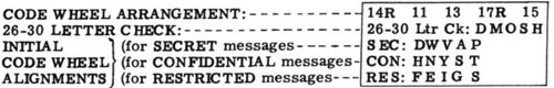
(1) For U.S. Navy use:
|
|
|
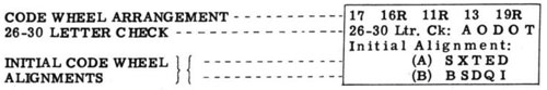
(2) For Combined (United States - British use):
|
|
|
(c) The Code Wheel Arrangement consists of five numbers corresponding to
the numbers
engraved on the Code Wheels. Any letter prefixes or suffixes of the
individual Code Wheel
designations are omitted and in some Key Lists only the final digit may be
shown.
(d) The 26-30 Letter Check is given as a means of checking the Code Wheel
Arrangement and
the operation of the machine.
(e) The Initial Code Wheel Alignment is provided for encipherment of the
Message Code Wheel
Alignment. Para. (b) (1) Illustrates a Key Setting designed for U. S. Navy
use only, and gives
three Initial Code Wheel Alignments, designated "SEC", "CON" and "RES" to
be used for SECRET,
CONFIDENTIAL and RESTRICTED messages respectively. Para. (b) (2)
illustrates a Key Setting
designed for Combined use, and gives two Initial Code Wheel Alignments,
designated "A" and "B"
respectively. The Key List in use will define, by means of a footnote, the
classifications of
messages for which "A" and "B" are to be used.
607. DEFINITIONS.
(a) In this method of operation, two different Code Wheel Alignments are
used, requiring
differentiation.
|
(1) The MESSAGE CODE WHEEL ALIGNMENT Is the alignment appearing on the Code
Wheels at
the start of the actual encipherment of the message. It consists of five
letters selected at random.
(2) The INITIAL CODE WHEEL ALIGNMENT is the alignment used in the process
of enciphering
(or deciphering) the Message Code Wheel Alignment It is given in the Key
List
|
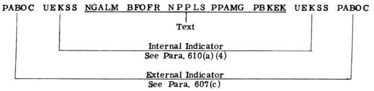
(b) The INTERNAL INDICATOR is the encipherment of the Message Code Wheel
Alignment, using
the Initial Code Wheel Alignment at the beginning of the encipherment
|
| |
-68-
|
|
(c) The EXTERNAL INDEATOR is provided for by the Key List, Rotating
Indicator List,
Crypto-Channel Charts, etc. Many of the crypto-channels in which the CCM is
used have been
assigned several Rotating Indicators for each classification. It is
important that these indicators
be used equally and in random order, and checked off as used so that an
Indicator will not be used
again until all the others have been employed, and so that an alphabetical
or other pattern will
not be apparent.
608. CODE WHEEL ARRANGEMENT.
(a) Remove CSP 1600 from its metal box by unscrewing the four thumb screws.
NOTE: CSP 887 may be stowed in the metal box while CSP 1600 is in use.
(b) Determine the proper set of Code Wheels to be used. Each Key List
contains this information in the Instructions. Choose the Key Setting corresponding to the date of the Date/Time Group to be used in the message. Insert the Code Wheels in CSP 1600 in accordance with the Code Wheel
Arrangement given in the Key Setting.
|
(1) The sequence given is positions #1 to #5 inclusive, for respective Code
Wheel positions in
CSP 1600. The letter "R" appearing after a Code Wheel number indicates the
Code Wheel so
designated is to be inserted in a reversed position (I.e., with the letters
appearing upside down
to the operator). Insert the Code Wheel Spindle and install CSP 1600 in the
machine, securing
it carefully by means of the four thumb screws.
|
609. 26-30 LETTER CHECK.
(a) The 26-30 Letter Check is provided for checking the Code Wheel
Arrangement and
operation of the machine. The five letter group given is the encipherment
of the letter "A" on the
26th to 30th steps inclusive using the Code Wheel Arrangement given in the
Key Setting with an
Initial Code Wheel Alignment of "OOOOO".
|
THE 26-30 LETTER CHECK SHALL BE MADE AFTER EACH CHANGE OF CODE WHEEL
ARRANGEMENT. ITS USE IS MANDATORY
|
(b) To make the 26-30 Letter Check:
|
(1) Prepare the machine for operation.
(2) Insert the Code Wheels according to the Arrangement given in the Key.
(3) Set the Code Wheels by hand to an Initial Alignment of "OOOOO".
(4) Set the Controller at "R" (Reset) and set the Zeroizer to "Operate". By
means of the "Blank"
Key, step the Code Wheels once.
(5) Set the Controller at "E" (Encipher), and reset the Counter to zero. By
means of the
"Blank" and "Repeat" Keys, step the Code Wheels twenty-five times.
(6) Type (Encipher) the letter "A" five times.
(7) Compare the resultant encipherment with the values given in the Key.
Any deviation
necessitates a complete re-check.
|
(c) If the correct 26-30 Letter Check is not produced see pars. 308(d).
610. ENCIPHERMENT.
(a) Having arranged the Code Wheels in accordance with the Key Setting and
having made the 26-30 Letter Check:
|
(1) Set the Controller at "P" (Plain), and set the Zeroizer to "Operate".
When using CSP 1600
the Zeroizer is set at "Operate" for all operations. Type the heading,
Date/Time Group, etc., and
any other data desired. Press the Tape release tab and advance the tape two
or three inches, or
space several times. Type the External Indicator and space once.
|
|
| |
-69-
|
|
(2) Select at random a group of five letters to use as the MESSAGE CODE
WHEEL ALIGNMENT.
Make a note of the five letter group on the message being enciphered for a
reference purpose in
case a verification is requested.
CAUTION: THE MESSAGE CODE WHEEL ALIGNMENT FOR EACH MESSAGE ENCIPHERED BY A
PARTICULAR KEY SETTING MUST BE DIFFERENT. THE SELECTION OF THE LETTERS MUST
BE
ENTIRELY AT RANDOM, THE LETTERS "O" AND "V" MUST NOT BE USED, AND THE
LETTERS MUST
NOT FOLLOW A REGULAR SYSTEM OF PROGRESSION. (See para. 329.)
(3) Select, from a Key Setting, the appropriate Initial Code Wheel
Alignment for the
classification of the message, and set the Code Wheels, by hand, to the
reference lines in
accordance with the designated letters. Set the Controller at "R" (Reset)
and, by means of the
"Blank" key, step the Code Wheels once, This is necessary because the CCM
Mark I enciphers
(or deciphers) and then steps the Code Wheels, whereas other devices
cryptographically
identical step the Code Wheels and then enciphers (or deciphers). (If the
Controller is set at "E"
when this is done, the machine will be in step, but the spacing of the five
letter code groups will
be displaced one letter.)
(4) Set the Controller at "E" (Encipher), and type (encipher) the MESSAGE
CODE WHEEL
ALIGNMENT (the five letter group selected at random in Paragraph (2)
above.) This
encipherment produces the INTERNAL INDICATOR.
(5) Set the Code Wheels, by hand, to the MESSAGE CODE WHEEL ALIGNMENT. Set
the Controller
at "R" and, by means of the "Blank" key, step the Code Wheels once.
(6) Set the Controller to "E" (Encipher), reset the Counter to zero.
(7) Type the text to be enciphered, using the space bar and alphabet keys
only. Spell out
numerals. The letter "X" shall normally be used to represent every mark of
punctuation. When
necessary for clarity, punctuation marks may be spelled out The only
abbreviations for
punctuation authorized are PAREN, PARA, and QUES. All punctuation shall be
kept at a minimum
and used only when necessary to attain clearness. The enciphered text will
appear on the tape in
groups of five letters. When padding is added at either or both ends to
conceal a particularly
short message, one in stereotyped form, or one which has been or may be
encrypted in another
system, the use of spaces and other stereotyped padding must be avoided.
(See Chapter IV,
Communication Instructions for example of objectionable padding.)
(8) When the text has been completely enciphered, note the counter reading.
If it is not a
multiple of five, set the controller to "P" (Plain), and type the letter
"X" as many times as are
needed to produce a reading which is a multiple of five. Space once.
(9) Set the Code Wheels, by hand, to the INITIAL CODE WHEEL ALIGNMENT. Set
the Controller at
"R" (Reset) and space once. Set the Controller at "E", and type (encipher)
the MESSAGE CODE
WHEEL ALIGNMENT. Check this group with the first INTERNAL INDICATOR
(10) Set the Controller at "P" (Plain) and type the EXTERNAL INDICATOR.
Advance the tape
through the tape channel until all the printing is clear, and tear off the
tape. |
611. CHECK DECIPHERMENT.
(a) As a check on accuracy, an enciphered message shall be check-deciphered
prior to
transmission, preferably by another coding officer, and if available, on a
second machine using
a different set of Code Wheels. In an emergency the check-decipherment may
be deferred until
after transmission, but should be completed as soon as possible. THE
CHECK-DECIPHERMENT IS
MANDATORY.
|
| |
-70-
|
|
612. EXAMPLE.
(a) The following example represents the appearance of a message enciphered
in this manner. It
is based on the sample Key Setting shown in para. 606 (b) (2). It is
assumed PABOC is the
CONFIDENTIAL External Indicator.
613. MESSAGE LENGTH.
(a) Very long messages to be enciphered with the CCM Mark 1 should be
broken up into parts,
each of which uses a different Message Code Wheel Alignment. Each part
should not exceed two-hundred (200) groups in length.
614. DECIPHERMENT.
(a) Using the Code Wheel Arrangement of the Key Setting as determined by
the Date/Time
Group, prepare the machine for operation. Make the 26-30 Letter Check.
(b) If any plain text is desired, set the Controller at "P" (Plain) and set
the Zeroizer at
"Operate". When using CSP 1600, the Zeroizer is set at "Operate" for all
operations.
(c) Select from the Key Setting, the appropriate Initial Code Wheel
Alignment for the
classification of the message and set the Code Wheels, by hand, to the
reference lines in
accordance with the designated letters. Set the Controller at "R" (Reset)
and, by means of the
"Blank" key, step the Code Wheels once. Set the Controller at "D"
(Decipher). Disregard the
External Indicator, and type (decipher) the Internal Indicator (the second
and next-to-the-last
groups of the message). This decipherment produces the MESSAGE CODE WHEEL
ALIGNMENT.
(d) Set the Code Wheels, by hand, to the Message Code Wheel Alignment, just
obtained. Set the
Controller at "R" (Reset), and by means of the "Blank" key, step the Code
Wheels once.
(e) Set the Controller at "D" (Decipher), and reset the Counter to zero.
Type (decipher) the
text of the message.
615. CLEARING GARBLES.
(a) If the letters of the Internal Indicator at the beginning and end of
the message are not
identical (due to errors of transmission) try the various combinations
until a Message Code
Wheel Alignment Is obtained that will give intelligible text.
(b) The External Indicator of one classification may have been used in the
message whereas, an
Initial Code Wheel Alignment of another classification may have been
erroneously employed.
(c) On decipherment if an "X" appears as a letter of the Message Code Wheel
Alignment and the
message does not "break" try substituting a "Z" for the "X".
(d) On decipherment, if a blank space appears as a letter of the Message
Code Wheel Alignment,
try substituting a "Z" for the blank spaces.
|
| |
-71-
|
|
ADJUSTMENTS
616. STEPPING MAGNET CONTACTS.
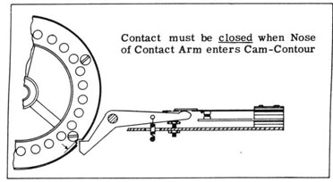
(a) Plate 13 illustrates the action of a Contact Operating Arm as
controlled by the Cam-contours of the Code Wheel. Plate 13A shows the nose of the Contact
Operating Arm resting in a
cam-contour, permitting the contact to close, and Plate 13B shows the nose
of the Contact
Operating Arm "riding" the periphery of the Code Wheel, holding the Contact
open.
|
CAUTION: IT IS A REQUIREMENT THAT THE STEPPING MAGNET CONTACTS POSITIVELY
"MAKE"
OR "BREAK" OTHERWISE CORRECT ENCIPHERMENT OR DECIPHERMENT IS IMPOSSIBLE. |
611. CONTACT ADJUSTMENTS.
(a) To check the adjustment of the Stepping Magnet Contacts:
|
(1) Insert the Code Wheels in accordance with the Code Wheel Arrangement to
be used.
(2) Rotate, by hand, the #3 (center) Code Wheel and observe the action of
either the left center
(#2) or right center (#3) contacts.
|
(A) When the nose of the Contact Operating Arm drops into a Cam-contour of
the Code Wheel,
the associated contact should be positively "closed" and the nose should
not touch the bottom of
the Cam-contour. This condition can be tested by rocking the Code Wheel
back and forth slightly
and observing the points at which the Code Wheel moves the Contact Arm.
(B) When the nose of the Contact Operating Arm rides the periphery of the
Code Wheel the
contact should be positively "opened".
|
|
(b) To adjust the Stepping Magnet Contacts:
(1) Rotate the Code Wheel until the nose of the Contact Arm is on the
periphery of the Code
Wheel. If necessary, bend the lower contact spring until the contact is
"just open".
(2) Rotate the Code Wheel until the nose of the Contact Operating Arm drops
into a Cam-contour. It should require only slight pressure to break the contact
between the upper and lower
contact springs. Adjust by bending the upper contact spring. The nose of
the contact arm should
clear the bottom of the cam-contour and the push-end of the contact
operating arm should
"barely clear" the upper Contact spring insulator. This adjustment is made
by turning the
adjustment screw.
|
| |
-72-
|
|
|
PLATE 13B
|
|
PLATE 13
|
| |
-73-
|
|
BLANK
|
| |
-74-
|
|
BLANK
|
| |
-75-
|
|
CSP 1100(C)
CONFIDENTIAL
-76-
|
|