a. In the event a round does not fire when the firing pin hits the primer, the following sequence of operations should be adhered to in replacing the unfired round with a fresh round:
(1) Recock immediately without opening the breech and refire. If the round does not function upon the second attempt, wait 30 seconds from the time the original misfire occurred. Then remove the round.
NOTE: To recock the 40-mm Automatic Gun MI (AA) without opening the breech, lift the hand operating lever slightly until the inner cocking lever is engaged by the check plunger; then return the hand operating lever to the normal firing position. The former operation will permit the breechblock to drop about 1/4 inch and cock the percussion mechanism; the latter operation will return the breechblock to the fully closed position and release the firing pin to strike the primer. Do not perform these operations with the top cover open.
(2) If it is impossible to remove the round in the normal manner within 45 seconds after the original misfire, and if the gun is hot, play water on the barrel. All personnel must stand clear of the gun. When the gun is cool, remove the round. If water is not available, stand clear of the gun until it is cool; then remove the round.
b. Removal of the round in the normal manner consists of elevating the gun to about 30 degrees and pulling the hand operating lever completely back past the rear latch bracket, a man being placed at the breech to catch the round as it slides out while the lever is being pulled backward.
c. If the round cannot be removed in the normal manner, due to the round sticking in the tube or the case separating from the projectile, remove the round with the hand cartridge extractor (par. 45 f), or with the hand shell ejector mounted on the cleaning staff M14 (par. 45 g).
121
NOTE: The possibility of a hangfire of more than 20 seconds after an attempt to fire is very remote in guns using fixed ammunition. The possibility of the propellent or the high-explosive filler being fired by the heat absorbed from a hot gun barrel increases with the length of time the round is in the gun. The safest time to remove a misfire is between 30 and 45 seconds after its occurrence.
49. BREECHBLOCK WILL NOT CLOSE.
a. In addition to the types of malfunction wherein the firing pin is released but fails to detonate the round, or the breechblock remains in open position due to mechanical obstruction, malfunctions have occurred wherein the breechblock is apparently closed, or very nearly so, and the firing pin is not released. Malfunctions of this type usually are the result of the following:
(1) Improper lubrication of the breech mechanism.
(2) Sand or burs in the breech mechanism.
(3) Deformation of the cartridge case.
b. Normally, such malfunctions may be corrected by proper lubrication of the breech mechanism, removal of sand and burs in the breech mechanism, or by the use of the hand cartridge extractor or the hand shell ejector to remove the cartridge case; however, instances have occurred in which a round of ammunition has become stuck in the firing chamber due to sand in the chamber or deformation of the cartridge case and at the same time the breechblock failed to close.
c. A malfunction of this type readily can be identified by the fact that the breechblock appears to be closed (or very nearly so) and cannot be opened by pulling the hand operating lever to the rear. This, of course, is due to the fact that the cartridge case jammed in the chamber will not permit the cartridge extractors to move to the rear, thus preventing the breechblock from descending.
d. In correcting malfunctions of this nature, particular care must be exercised to insure that the breechblock will not accidentally close and fire the round while the malfunction is being corrected. Failure to take necessary precautions will result in injury to personnel and damage to materiel. To clear malfunctions of this type, the following steps should be taken by the using arm personnel after the second attempt to fire has been made and the gun has cooled:
(1) Insure that the outer safety lever is on "SAFE," that the gun is pointed to a safe field of fire, and that the weapon is elevated approximately 30 degrees.
(2) Pull the hand operating lever as far back as it will go and maintain a steady tension or pull on the lever tending to pull the breechblock down.
122
(3) While tension is being maintained on the hand operating lever, remove the top cover and use a wood block and maul to drive the breechblock down into cocked position.
(4) Catch the extracted round as it slides out of the chamber. If the cartridge does not freely slide out of the chamber, it may be removed either with the hand cartridge extractor or the hand shell ejector.
e. In the event that the malfunction cannot be corrected by this procedure, notify ordnance maintenance personnel.
50. FEED CONTROL THUMB LEVER TO LEFT AND GUN FAILS TO FIRE.
a. Rammer Shoe to Rear and Round on Loading Tray.
Cause
Correction
Insufficient ammunition in automatic loader.
Insert loaded clip to continue firing.
Broken rammer shoe plunger spring.
Notify ordnance maintenance personnel.
Broken rammer spring or springs.
Notify ordnance maintenance personnel.
Firing mechanism not properly adjusted.
Make required adjustment (par. 67 f).
Rammer check levers or catch lever out of adjustment and will not release rammer shoe.
Notify ordnance maintenance personnel.
b. Rammer Shoe Forward and No Round on Loading Tray.
Jammed feed pawls.
Unload and release feed pawls.
Rounds not properly loaded in automatic loader.
Unload and load properly.
Loading tray jammed on feed rod roller or rollers.
Notify ordnance maintenance personnel.
c. Rammer Shoe Forward and Round on Loading Tray.
Rammer check levers or catch lever worn, damaged, or out of adjustment.
Notify ordnance maintenance personnel.
Gun breech side cover unlocked during firing. Breechblock did not open.
Carefully remove round that has been slammed against breech block. Remove breech mechanism to inspect for possible damage. Inspect side cover latch. Request ordnance maintenance personnel to replace worn or damaged parts.
123
51. FEED CONTROL THUMB LEVER TO RIGHT AND GUN FAILS TO FIRE.
a. No Round on Loading Tray, Rammer Shoe Forward, Breech Open, and One Round in Feed Pawls.
Cause
Correction
Insufficient ammunition in automatic loader.
Unload round if firing is to be discontinued. Reload if firing is to be continued.
Feed control thumb lever linkage incorrectly assembled, or out of adjustment.
Notify ordnance maintenance personnel.
b. Misfeed. No Round Brought Down on Loading Tray.
Clips loaded with bottom round not parallel to top of loader.
Push down on rounds; if resistance is met, remove all rounds from loader and inspect for irregularities in ammunition or clip.
Improper assembly of feed rods.
Notify ordnance maintenance personnel.
c. Rammer Shoe Forward, Round in Chamber, and Breechblock Partially Closed (par. 49).
Excessive grease in firing chamber.
Unload, clean chamber thoroughly, and inspect.
Burs or scoring on parts of breech mechanism or breech ring.
Notify ordnance maintenance personnel.
Breech ring outer crankshaft bent.
Disassemble breech mechanism and replace damaged parts.
Loose projectile.
Remove round with hand shell ejector.
Breech ring closing spring broken.
Remove closing spring case assembly and replace spring.
d. Rammer Shoe Forward, Round block Open, and Breechblcok Open.
Breech ring closing spring broken.
Remove closing spring case assembly and replace spring.
e. Rammer Shoe Forward, No Round in Chamber, and Breech-block Open.
Broken feed roller catch head, catch head arm, or catch head spring.
Notify ordnance maintenance personnel.
f. Rammer Shoe Forward, Round on Loading Tray, and Breechblock Open.
Rammer check levers or catch lever worn, broken, or out of adjustment
Notify ordnance maintenance personnel.
124
Cause
Correction
Gun breech side cover unlocked during firing. Breechblock did not open.
Carefully remove round that has been slammed against breech-block. Remove breech mechanism to inspect for possible damage. Inspect side cover latch. Request ordnance maintenance personnel to replace worn or broken parts.
g. Rammer Shoe Forward, Round in Chamber breechblock Closed.
Broken firing pin.
Remove breechblock and disassemble percussion mechanism. Replace worn or broken parts. Check protrusion of firing pin with gage before installing breechblock.
Firing pin protrusion insufficient.
Replace firing pin. Check firing pin protrusion with gage before installing breechblock.
Firing pin incorrectly assembled.
Assemble correctly.
52. OTHER MALFUNCTIONS OF GUN.
a. Cartridge Case Partially Ejected, or Failure to Eject.
Broken rammer spring. (Rammer levers retard movement of spent cartridge case.)
Notify ordnance maintenance personnel.
b. Failure to Single Fire.
Firing mechanism not properly adjusted.
Make required adjustment (par. 67 f).
Rammer will not release. Broken or missing rammer lever plunger spring.
Notify ordnance maintenance personnel.
Firing lever pawl rusty or damaged.
Notify ordnance maintenance personnel.
Firing lever pawl plunger spring broken or missing.
Notify ordnance maintenance personnel.
c. Hand Operating Lever Will Not Cock Rammer Shoe.
Firing rod linkage incorrect. Hand operating lever shaft striking front nose of firing lever.
Notify ordnance maintenance personnel.
125
Cause
Correction
d. Automatic Loader Feed Rollers Fail To Rotate.
Feed roller catch head taper pin out of position.
Notify ordnance maintenance personnel.
e. Gun Breech Top Cover Damaged or Broken.
Failure to latch top cover before firing.
Notify ordnance maintenance personnel.
Breech ring barrel catch not engaging slot in tube, thus preventing the proper closing and latching of top cover.
Notify ordnance maintenance personnel.
53. RECOIL MECHANISM.
a. Recoil Violent or Excessive in Length.
Insufficient liquid in recoil cylinder.
Refill recoil cylinder as prescribed (par. 66 c).
Weak or broken recuperator spring.
Change barrel assemblies. If this corrects condition, refer original barrel assembly to ordnance maintenance personnel for replacement of recuperator spring.
b. Recoil Slow.
Breech ring guides and guideways in breech casing lack lubrication or are dirty.
Lubricate properly. Remove dirt and congealed oil.
Burs on breech ring guides and guideways of breech casing.
Notify ordnance maintenance personnel.
Barrel guide sleeve and locking collar loose.
Tighten barrel guide sleeve locking collar. Tightly screw in barrel guide sleeve locking collar set screw and barrel locking collar set screw friction disk.
Barrel guide sleeve burred or damaged.
Notify ordnance maintenance personnel.
c. Counterrecoil Slow.
Breech ring guides and guideways in breech casing lack lubrication or are dirty.
Lubricate properly. Remove dirt and congealed oil.
Damaged or burred breech ring guides and guideways of breech casing.
Notify ordnance maintenance personnel.
Incorrect setting of control rod valve spindle.
Adjust setting of spindle as required (par. 38 b).
126
Cause
Correction
Weak or broken recuperator spring.
Change barrel assemblies. Refer original barrel assembly to ordnance maintenance personnel.
Feed rods binding in automatic loader.
Notify ordnance maintenance personnel.
d. Counterrecoil Violent.
Loss of liquid in recoil cylinder.
Refill recoil cylinder as prescribed (par. 66 c).
Incorrect setting of control rod valve spindle.
Adjust setting of spindle as required (par. 38 b).
e. Failure to Counterrecoil.
Control rod valve spindle closed.
Adjust setting of spindle as required (par. 38 b).
Damaged or burred breech ring guides or guideways in breech casing.
Notify ordnance maintenance personnel.
Weak or broken recuperator spring.
Change barrel assemblies. Refer original barrel assembly to ordnance maintenance personnel.
Loading tray jammed on automatic loader feed rods.
Notify ordnance maintenance personnel.
54. ELEVATING AND TRAVERSING MECHANISMS.
a. Backlash in Elevating and Traversing Mechanisms.
Wear and improper meshing of worm, wormwheel, gears, or traversing arc; improper assembly of gears; end play in gear shafts.
Notify ordnance maintenance personnel.
b. Excessive Handwheel Effort Necessary To Elevate and Depress.
Equilibrators out of adjustment.
Adjust equilibrators (par. 67 b).
Equilibrator spring or springs weak or broken.
Notify ordnance maintenance personnel.
Parts improperly mated, worn, or damaged; lack of lubricant; dirty or gummy lubricant; elevating arc binding; ball bearings "locking up."
Notify ordnance maintenance personnel.
127
55. FRONT AND REAR AXLES.
a. Front Axle Loose in Swivel; Rear Axle Loose in Bearings.
Cause
Correction
Chassis compensating spring lock and arc disengaged, worn, or damaged. Lock broken due to excessive pressure on handle when not properly engaged. Ice in housing preventing operation of lock.
Keep locking handle in locked position and secured with strap and clip; wire handle down if necessary. Notify ordnance maintenance personnel (par. 67 e).
Loose or worn bearings in swivel or rear girder.
Notify ordnance maintenance personnel.
b. Axles, Cross Heads, Springs, Shackles, or Spindles Bent or Broken.
Heavy road shocks.
Notify ordnance maintenance personnel.
56. WHEELS AND TIRES.
a. Front Wheel Shimmy.
Looseness or excessive wear in steering mechanism.
Notify ordnance maintenance personnel.
Loose or broken wheel bearings.
Adjust bearings. If damaged or broken, notify ordnance maintenance personnel.
Dragging front wheel brakes.
Notify ordnance maintenance personnel.
b. Excessive Tire Wear.
Misalignment of wheels.
Notify ordnance maintenance personnel.
Wheels bent or loose on hubs; wheel bearings loose.
Adjust bearings. Tighten loose wheel retaining nuts. Replace bent wheels.
Low inflation pressure.
Keep tires inflated to recommended pressure, 45 pounds per square inch.
57. ELECTRIC BRAKES.
a. No Braking, or Intermittent Braking.
Broken wire in circuit.
Check entire wiring for broken wires. Repair or replace.
Broken wire in magnet.
If broken wire is on outside of magnet, repair if possible. If no current flows through magnet, notify ordnance maintenance personnel.
128
Cause
Correction
Controller defective.
Notify ordnance maintenance personnel.
Poor connections.
Check, clean, and tighten all connections at brake, controller, load control, and sockets.
Poor ground condition in circuit.
Clean up and tighten all connections.
Defective plug or socket.
Check for loose connections, dirty or corroded blades, or broken socket. Repair, or replace with new socket.
b. Very Weak Brakes.
Worn out or greasy brake lining.
Lining may be worn to full extent of magnet travel. Refer to ordnance maintenance personnel for new lining.
Glazed magnet facing.
Roughen facing of magnet with PAPER, flint, class B, No. 1.
Foot control out of adjustment on prime mover.
When carriage brakes are adjusted, effective range of controller is changed. This throws controller out of adjustment. Reset to cover full range of controller.
Wire broken in insulation; bare wire; loose connection; poor contact at load control.
Check wiring and connections for defects. Short out load control. Correct if possible; otherwise, notify ordnance maintenance personnel.
Insufficient current.
Test with ammeter (par. 67 i (2)). Clean up and tighten all connections. Check plug and socket for corroded or dirty blades, or broken socket. Replace broken parts.
Stop lights connected in circuit.
Check to determine if stop lights have been connected in circuit by mistake.
Poor ground connections.
Ground contacts must be solid and clean.
Worn wheel bearings.
Refer to ordnance maintenance personnel.
129
c. Brakes Grabbing.
Cause
Correction
Loose or worn wheel bearings.
Tighten bearings. If this does not correct condition, refer to ordnance maintenance personnel for replacement of bearings.
All brakes not working.
Check current at brakes with ammeter (par. 67 i (2)). Check for broken wires and poor connections.
Sticky or grease-coated lining.
Wash lining with SOLVENT, dry-cleaning.
Contactor arm of controller pitted.
Smooth out contactor arm with PAPER, flint, class B, No. 1.
Stop lights in brake circuit.
Determine if stop lights have been connected improperly.
Poor electrical connections.
Check wiring for loose connections, bare wires, or wires broken in insulation.
Worn lining; drums out of round; lining loose on rivets; broken or weak band or magnet springs; controller burned out; poor contactor blade spacing; magnet bushing worn.
Refer to ordnance maintenance personnel.
d. Brakes Dragging.
Drums out of round; broken spring in hand control; insufficient spacing between armature and magnet; band distorted; unequal clearance; insufficient lining clearance; loose or damaged wheel bearings.
Refer to ordnance maintenance personnel.
e. Battery on Carriage Runs Down.
Safety switch left in "ON" position.
Keep safety switch lever in "OFF" position.
Excessive use of battery to apply brakes.
Do not use battery current for parking; use hand brakes. Use battery current for braking only as necessary.
Short circuit in brake system.
Check for bare wire. Tape or replace damaged cable.
130
58. LIGHTS.
a. Dim Lights.
Cause
Correction
Loose or corroded connections.
Clean and tighten all connections.
High resistance in blackout light switch.
Notify ordnance maintenance personnel.
Damaged wires.
Check for broken or bare wires.
b. Flickering Lights.
Loose or damaged plug or socket.
Check plug and socket. Tighten. Replace if broken.
Loose or bare wires; loose connections; loose bulbs.
Check wiring and connections. Cover or replace bare wires. Tighten loose connections and bulbs.
Section VI LUBRICATION
59. INTRODUCTION.
a. General. Lubrication is an essential part of preventive maintenance, determining to a great extent the serviceability of parts and assemblies. Satisfactory operation and long life of the materiel are not assured unless the materiel is kept clean and well lubricated.
b. Apply sufficient lubricants, but avoid wasteful practices. Excessive lubrication will result in dust accumulations on some moving parts and, if not removed, may cause wear and malfunctioning. Particular attention should be given to the lubrication of sliding surfaces which contain no oilholes, plugs, or fittings. Keep all exposed parts clean and well lubricated. The materiel should always be lubricated after washing.
c. Supplies. In the field, it may not be possible to supply a complete assortment of lubricants called for by the lubrication guide to meet the recommendations. It will be necessary to make the best use of those available, subject to inspection by the officer concerned, in consultation with responsible ordnance personnel.
60. LUBRICATION GUIDE.
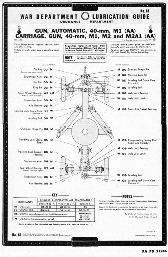
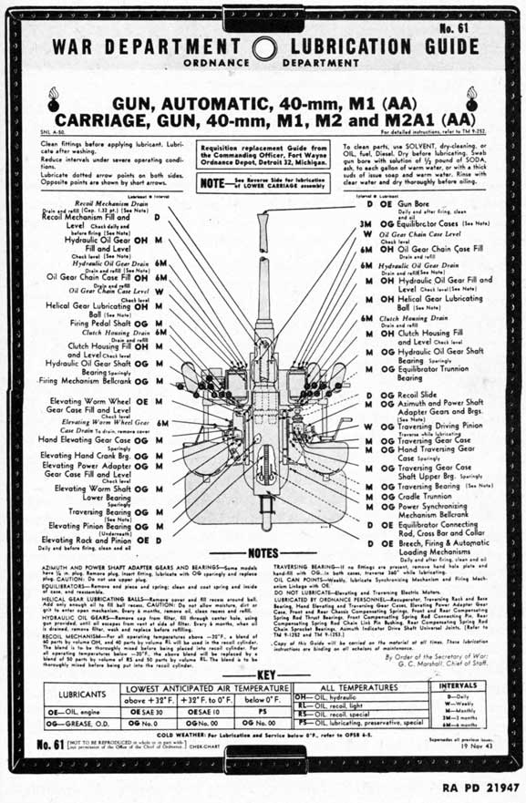
a. War Department Lubrication Guide No. 61 (figs. 108 and 109) prescribes first and second echelon lubrication maintenance. Lubrication to be performed by ordnance maintenance personnel is covered in TM 9-1252 and TM 9-1253.
131
LUBRICATION
b. A lubrication guide is placed on or is issued with each item of materiel, and is to be carried with it at all times. In the event the materiel is received without a guide, the using arms shall immediately requisition a replacement from the Commanding Officer, Fort Wayne Ordnance Depot, Detroit 32, Michigan.
c. Lubrication instructions on the guide are binding on all echelons of maintenance and there shall be no deviations, except as indicated in subparagraph d, below.
d. Service intervals specified on the guide are for normal operating conditions. These intervals will be reduced under extreme conditions such as excessively high or low temperatures, prolonged periods of operation, continued operation in sand or dust, immersion in water or exposure to moisture, any one of which may quickly destroy the protective qualities of the lubricant.
e. Lubricants are prescribed in the "Key" in accordance with three temperature ranges, "above +32 F," "+32 F to 0 F," and "below 0 F." When to change grades of lubricants is determined by maintaining a close check on operation of the materiel during the approach to change-over periods, especially during initial action. Sluggish action is an indication of lubricants thickening and the signal to change to grades prescribed for the next lower temperature range. Ordinarily it will be necessary to change grades of lubricants only when air temperatures are consistently in the next higher or lower range, unless malfunctioning occurs sooner due to lubricants being too thin or too heavy.
f. Lubrication Equipment.
(1) Each piece of materiel is supplied with lubrication equipment adequate to maintain the materiel. This equipment will be cleaned both before and after use.
(2) Lubrication guns will be operated carefully and in such manner as to insure a proper distribution of the lubricant.
g. Points of Application.
(1) Lubrication fittings, grease cups, oilers, and oilholes are readily identifiable on the materiel by a red circle. Such lubricators and the surrounding surface will be wiped clean before lubricant is applied.
(2) Where relief valves are provided, apply new lubricant until the old lubricant is forced from the vent. Exceptions are specified in notes on the lubrication guide.
h. Cleaning. SOLVENT, dry-cleaning, or OIL, fuel, Diesel, will be used to clean or wash all parts. Use of gasoline for this purpose is prohibited. After washing, parts will be thoroughly dried before applying lubricant. Swab gun bore with solution of 1/2 pound of SODA ASH to each gallon of warm water, or with a thick suds of issue soap and warm water. Rinse with clear water and dry thoroughly before oiling.
132
Figure 108 - Lubrication Guide
133
Figure 109 - Lubrication Guide
134
i. Azimuth and Power Shaft Adapter Gears and Bearings. Monthly, lubricate with GREASE, O.D., No. 0, above +32 F or GREASE, O.D., No. 00, below + 32 F. Some models have 1/4-inch plug. To lubricate, remove plug and insert fitting. CAUTION: Do not use upper plug or over lubricate.
j. Breech, Firing, and Automatic Loading Mechanisms. Daily and before and after firing, clean and oil all moving parts and unpainted metal surfaces with OIL, engine, SAE 30, above +32 F; OIL, engine, SAE 10, from + 32 F to 0 F; OIL, lubricating, preservative, special, below 0 F. CAUTION: To insure easy breech operation and to avoid misfiring in cold weather, clean, dry, and lubricate with OIL, lubricating, preservative, special. To clean firing mechanism, remove and operate pin in SOLVENT, dry-cleaning.
k. Equilibrators. Every 3 months, remove end piece and spring; clean and coat spring and inside of case with GREASE, O.D., No. 0, above +32 F, or GREASE, O.D., No. 00, below +32 F. CAUTION: Use equilibrator spring compressor to remove spring.
l. Helical Gear Lubricating Balls. Remove cover and fill recess around ball with OIL, hydraulic. Add only enough oil to fill ball recess. CAUTION: Do not allow moisture, dirt, or grit to enter open mechanism. Every 6 months, remove oil, clean recess, and refill.
m. Hydraulic Oil Gears. Remove cap from filter, fill with OIL, hydraulic, through center hole, using gun provided, until oil escapes from vent at side of filter. Every 6 months, when oil is drained, remove filter, wash, and replace before refilling.
n. Recoil Mechanism. For all operating temperatures above -20 F, a blend of 60 parts by volume of OIL, hydraulic, and 40 parts by volume of OIL, recoil, light, will be used in the recoil cylinder. The blend is to be thoroughly mixed before being placed in recoil cylinder. For all operating temperatures below -20 F, the above blend will be replaced by a blend of 50 parts by volume of OIL, recoil, special, and 50 parts by volume of OIL, recoil, light. The blend is to be thoroughly mixed before being put into the recoil cylinder. Capacity 1.32 pints.
o. Traversing Bearing. Monthly, lubricate traversing bearing with GREASE, O.D., No. 0, above + 32 F or GREASE, O.D., No. 00, below +32 F through the fittings. If no fittings are present, remove handhole plate and hand-fill with GREASE, O.D., No. 0, above +32 F, GREASE, O.D., No. 00, below + 32 F. In both cases, traverse 360 degrees while lubricating.
p. Wheel Bearings. Remove bearing cone assemblies from hub. Wash bearings, cones, spindle, and inside of hub, and dry thoroughly. Do not use compressed air. Inspect bearing races and replace if damaged. Wet the spindle and inside of hub and hub cap with
135
GREASE, general purpose, No. 2, to a maximum thickness of IA G inch only to retard rust. Lubricate bearings with GREASE, general purpose, No. 2, with a packer, or by hand, kneading lubricant into all spaces in the bearing. Use extreme care to protect the bearings from dirt, and immediately reassemble and replace wheel. Do not fill hub or hub cap. The lubricant in the bearing is sufficient to provide lubrication until the next service period. Any excess might result in leakage into the drum. Adjust bearings in accordance with instructions in paragraph 88 d.
q. Oil Can Points. Weekly, lubricate power synchronizing mechanism and firing mechanism linkage, drawbar traveling lock, brake levers, inner tie rod ends, clevises, linkage with OIL, engine, SAE 30, above +32 F, or OIL, engine, SAE 10, from +32 F to 0 F; use OIL, lubricating, preservative, special, below 0 F.
r. Do Not Lubricate. Elevating and traversing electric motors.
s. Lubricated by Ordnance Personnel.
(1) TRAVERSING RACK AND BASE BEARING. Every 6 months, disassemble, clean, and lubricate with GREASE, O.D., No. 0, above +32 F or GREASE, O.D., No. 00, below +32 F.
(2) HAND ELEVATING AND TRAVERSING GEAR CASES AND ELEVATING POWER ADAPTER GEAR CASE. Every 6 months, disassemble; clean housing and enclosed parts. Repack with GREASE, O.D., No. 0, above +32 F or GREASE, O.D., No. 00, below +32 F.
(3) RECUPERATOR. Every 6 months, remove recuperator, disassemble, and apply a thin coat of GREASE, O.D., No. 0, above + 32 F or GREASE, O.D., No. 00, below +32 F to spring and inside of case.
(4) FRONT CHASSIS COMPENSATING SPRING, FRONT COMPENSATING SPRING ROD THRUST BEARING, AND FRONT COMPENSATING SPRING ROD CONNECTING PIN. Every 6 months, remove compensating spring and spring rod thrust bearing from compensating spring housing and clean all parts. Repack bearing and coat spring. Coat inside of spring housing and swivel body. Use GREASE, O.D., No. 0, above +32 F or GREASE, O.D., No. 00, below +32 F. Remove axle lock and cover assembly to facilitate removal of plug from compensating spring rod connecting pin. Insert fitting and lubricate with GREASE, O.D., No. 0, above +32 F, or GREASE, O.D., No. 00, below +32 F. Before replacing cover, wipe the compensating locating arc clean and recoat with GREASE, O.D., No. 0, above + 32 F or GREASE, O.D., No. 00, below +32 F.
(5) REAR CHASSIS COMPENSATING SPRING, REAR COMPENSATING SPRING ROD THRUST BEARING, REAR COMPENSATING SPRING ROD CHAIN LINK PIN BUSHING, AND REAR COMPENSATING SPRING ROD CHAIN SPROCKET BEARINGS. Every 6 months, remove rear compensating spring unit and chain from chassis frame. Disassemble and clean all parts. Repack spring rod thrust bearing and coat compensating
136
spring and inside of spring housing with GREASE, O.D., No. 0, above +32 F or GREASE, O.D., No. 00, below +32 F. Apply 6 or 8 drops of OIL, engine, SAE 30, above +32 F, OIL, engine, SAE 10, from +32 F to 0 F; or OIL, lubricating, preservative, special, below 0 F to each roller of the compensating spring rod chain. Work the oil in between the rollers and connecting links and wipe off excess. Disassemble the chain sprocket bearings, clean, and repack with GREASE, O.D., No. 0, above +32 F or GREASE, O.D., No. 00, below +32 F. Wipe the compensating arc clean, coat teeth, and lubricate the compensating rod chain link pin bushing through fitting with GREASE, O.D., No. 0, above +32 F or GREASE, O.D., No. 00, below +32 F. Replace covers and lubricate the compensating spring rod chain and sprocket as prescribed in the lubrication guide.
(6) AZIMUTH INDICATOR DRIVE SHAFT UNIVERSAL JOINTS. Every 6 months, remove, clean, and repack with GREASE, O.D., No. 0, above +32 F or GREASE, O.D., No. 00, below +32 F.
61. REPORTS AND RECORDS.
a. Reports. Unsatisfactory performance of materiel will be reported to the ordnance officer responsible for maintenance.
b. Records. A complete record of seasonal changes of lubricants and recoil oils will be kept in the artillery gun book for the materiel.
Section VII CARE AND PRESERVATION
62. GENERAL.
a. It is of vital importance that all parts of the materiel be kept in proper condition in order that the weapon be ready for immediate service at all times. Lubricating, cleaning, and preserving materials provided with the gun and carriage will enable the personnel to keep the parts in proper working condition. This section of the manual prescribes the uses of these materials. Section VI prescribes lubrication instructions for normal conditions. Section XIV prescribes special precautions to be taken for operation under unusual conditions.
b. Moving parts of the various mechanisms should be lubricated in the prescribed manner, and periodical examinations should be made to insure that the lubricant is reaching the parts for which it is intended, and to insure that the weapon as a whole is receiving the attention necessary for satisfactory operation. Vigilance should be exercised by all members of the using arm personnel to note and report any irregularity in the operation or functioning of the gun and mount.
137
c. Dirt and grit, accumulated in traveling or from the blast of the piece in firing, settle on bearing surfaces, and in combination with the lubricant itself, form a cutting compound. Powder fouling attracts moisture and hastens the formation of rust. It is essential that all parts be cleaned at frequent intervals, depending upon use and service.
d. If rust should accumulate, its removal from bearing surfaces requires special care in order that clearances shall not be unduly increased. CLOTH, crocus, should be used for this purpose. The use of coarse abrasives is strictly forbidden.
e. In disassembly, assembly, or inspection, extreme care must be exercised to prevent dust, dirt, or other foreign matter from entering the mechanisms.
f. When materiel is not in use, the proper covers must be used.
g. When the weapon is to be unused for more than one week, the bore, breech mechanism, and bright unpainted surfaces should be cleaned with SOLVENT, dry-cleaning, and the surfaces coated with COMPOUND, rust-preventive, light. Parts coated with this compound should be examined weekly and the compound renewed if necessary.
h. Should an enemy shell or bomb burst near the weapon, it must be determined that the weapon has not been damaged to a dangerous degree before the next round is fired. Damage of a serious nature should be reported to the ordnance officer.
63. ORGANIZATION SPARE PARTS AND ACCESSORIES.
a. All organization spare parts, tools, and accessories should be kept in an orderly manner so that they can be located quickly when required. They should be protected from loss or damage by being kept in their proper rolls and chests. Those items susceptible to rust and corrosion must be cleaned thoroughly at regular intervals and coated with a film of oil. Parts supplied in protective containers should be kept in the containers until required.
b. The sets of organization spare parts and accessories for the gun and carriage should be maintained as completely as possible at all times. The sets should be checked with the lists in the Standard Nomenclature Lists (sec. XV), and all used parts, and all missing parts, tools, and accessories should be replaced immediately.
64. CLEANING AFTER FIRING.
a. Bore. The bore of the barrel should be thoroughly cleaned, rinsed, dried, and oiled immediately after firing and while the gun is still warm. This procedure is to be repeated each day until sweating ceases. The purpose of the repeated cleanings is to remove the effects of sweating, a chemical reaction of the burned powder composition which cannot be removed with the initial procedure.
138
(1) The cleaning procedure can be done most easily if the barrel is removed. In this case, the cleaning operations are conducted from the breech end of the barrel. The barrel can be cleaned while mounted in place with the breechblock and extractors removed. Such cleaning operations must be conducted from the muzzle end of the barrel.
(2) CLEAN.
(a) For cleaning, use a solution made by dissolving 1/2 to 1 pound of SODA ASH in 1 gallon of boiling water, or CLEANER, rifle bore, or a solution of boiling water and issue soap.
CAUTION: Do not use SOLVENT, dry-cleaning.
(b) Assemble the three sections of the cleaning staff M14. Wrap the end of the staff with pieces of cloth soaked in the solution or cleaner. With two men on the staff, work the staff through the bore, using a pushing and pulling action. A pad or swab may be made of cloths, soaked in the solution, and pushed repeatedly through the bore. Wash the bore thoroughly in this manner.
NOTE: In the absence of SODA ASH, CLEANER, rifle bore, or issue soap, hot water may be used alone. SOLVENT, dry-cleaning, should not be used because the corrosive salts from the powder composition, which cause rust, are not readily dissolved by petroleum products; they are readily dissolved by water solutions.
(3) RINSE. Follow the cleaning operation by rinsing the bore to remove the cleaning solution. Wrap the end of the staff with cloths soaked in clean, hot water, or use swabs soaked in clean, hot water. Follow the procedure described for cleaning.
(4) DRY. Follow the procedure prescribed for cleaning, using the same accessories and methods but substituting dry cloths for wet ones.
(5) INSPECT. Inspect the barrel for flaws, cracks, or other defects which would make it unfit for further service. Report any defects to ordnance maintenance personnel.
(6) OIL. Assemble the bore brush M29 to the cleaning staff. Place the brush over a bucket to catch the oil which drips from the brush and apply oil to the brush. Use OIL, engine, SAE 30, for temperatures above 32 F, or OIL, engine, SAE 10, for temperatures below 32 F. Apply a coating of oil to the bore.
NOTE: Special instructions for cleaning the gun at temperatures below 32 F are given in paragraph 123.
b. Barrel Exterior. With a clean cloth, apply a coating of light oil to all exterior parts not painted or otherwise protected against rusting.
c. Breech Mechanism. After firing, the breechblock, inner cranks, and extractors should be removed (par. 80), the breechblock
139
should be disassembled (par. 82), and all parts should be cleaned and oiled thoroughly, assembled, and installed. Special attention should be given to the firing pin and inner and outer cocking levers. The hole in the firing pin bushing or in the front of the breechblock must be checked to insure that it is clean and unobstructed. The protrusion of the firing pin through this hole in firing position must be checked frequently with the striker protrusion gage. Any malfunction, weak or broken spring, or broken or deformed part should be corrected or replaced, if this work can be performed by the using arm personnel; otherwise, the condition should be reported to the ordnance maintenance personnel.
65. GUN.
a. Barrel Assembly.
(1) Guns become copper-fouled to less extent when cared for in the proper manner. Wear in the bore does not depend entirely upon the number of rounds fired but also on the care given the bore in cleaning and cooling between periods of firing.
(2) Since the accuracy life of a gun is decreased by a fast rate of firing and the attendant heat, the gun should be allowed to cool and should be washed as often as practical. Barrel assemblies should be changed during firing whenever necessary because of overheating. Each projectile must be cleaned before it is placed in the rack preparatory to firing. The bore should be cleaned before firing.
(3) It is important that, whenever possible, the gunner inspect the bore to make certain that it does not contain any extraneous particles that might cause damage to the gun.
(4) Make certain that the barrel guide sleeve and locking collar are properly positioned at all times, and that the barrel guide sleeve locking collar set screw and the barrel locking collar set screw friction disk are tightly screwed into place. If this set screw is not properly tightened, the barrel guide sleeve and locking collar have a tendency to work loose. This condition will allow the recuperator spring to expand and will result in faulty recoil and counterrecoil.
(5) It will be the responsibility of battery personnel to see that the barrel guide sleeve and locking collar are properly positioned at all times, and that the barrel guide sleeve locking collar set screw, and the barrel locking collar set screw friction disk, are tightly screwed into place.
(6) The recuperator spring collar wrench B200473 is to be used in tightening the barrel guide sleeve locking collar, and may be obtained by requisition through regular channels on a basis of one per battery.
(7) The flash hider cover should be in place when the gun is not being fired.
CAUTION: Copper fouling must not be removed under any circumstances.
140
b. Regular Cleaning Procedure.
(1) When the gun is not being fired, this cleaning procedure is to be followed at intervals specified by the officer in charge. The interval will be dependent upon atmospheric, traveling, or other conditions.
(2) This cleaning procedure is the same as that specified in paragraph 64 a, except that SOLVENT, dry-cleaning (which readily removes oil and dirt), is used in place of the SODA ASH or issue soap solutions.
c. Inactivity. If the weapon is to be unused for more than a week, the bore should be given a coating of COMPOUND, rust-preventive, light.
d. Breech Mechanism.
(1) At frequent intervals, when the gun is not being fired, the breech mechanism will be disassembled, cleaned, oiled, and assembled. These intervals will be specified by the officer in charge, and their frequencies will be dependent upon atmospheric and other conditions.
(2) The automatic loader hood and shield should be in place when the gun is not actually in use, to prevent dust and grit from getting into the mechanism, causing wear, and impeding smooth operation. Covers must be kept closed and locked.
(3) If the breech mechanism does not operate smoothly, or if the mechanism requires a greater effort than usual when operated with the hand operating lever, it should be disassembled and the cause determined. If corrective measures are beyond the scope of the using arm personnel, the matter should be brought to the attention of the ordnance maintenance personnel. Any part showing signs of scoring or burs must be replaced.
e. Barrel Assembly Removal. The barrel assembly may be removed from the breech ring by using arm personnel (par. 79). The barrels of the 40-mm Automatic Gun M1 (AA) are interchangeable.
66. RECOIL MECHANISM.
a. General.
(1) It is extremely important that the recoil cylinder be filled in the prescribed manner and that the recoil mechanism be correctly prepared for action. Should these operations be performed incorrectly, should the recoil cylinder anchor bracket be mounted in reverse position (par. 86 f), or should there be an appreciable loss of liquid, unsatisfactory recoil or counterrecoil must be expected and serious damage to the mechanism may result. To insure that the recoil mechanism is kept in good order, it is important that it be cared for by trained personnel.
(2) The energy of recoil is absorbed mainly in the recoil cylinder although a certain amount of the energy is taken up and stored by the
141
recuperator spring on the tube. Additional energy is absorbed in overcoming the friction in the slides and packing.
(3) The recoil energy taken up and stored by the recuperator spring is used to return the gun into battery in counterrecoil. The speed of counterrecoil is controlled by the counterrecoil buffing action of the recoil cylinder. This is governed by the counterrecoil adjusting valve and adjusted by turning the squared head of the control rod valve spindle which protrudes from the front end of the recoil cylinder.
(4) The length of recoil cannot be adjusted by turning the control rod valve spindle; this merely adjusts speed of counterrecoil.
b. Length of Recoil.
(1) The recoil should be smooth and the length of recoil should be between 7.4 and 8.3 inches. The most desirable length is 7.83 inches. The method of measuring the length of recoil is described in paragraph 44 b. The length of recoil is measured while the gun is being fired by means of the recoil indicator.
(2) The extreme length of recoil is fixed by the dimension between the recoil cylinder piston and the rear end of the recoil cylinder which forms a seating for the packing. Maximum recoil is approximately 8.8 inches. This length, however, should not be reached, as a recoil of such length will result in damage to the mechanism.
(3) If the length of recoil does not come within the proper limits, check the fluid level in the recoil cylinder. Fill to the proper level, if necessary. If recoil is unsatisfactory with a properly filled recoil cylinder, the cause may be a weak or broken recuperator spring; change barrel assemblies.
(4) If the length of recoil is corrected by changing barrels, this would indicate that the recuperator spring on the original barrel was unsatisfactory. This must be reported to ordnance maintenance personnel for checking and replacement if found necessary.
(5) If changing barrel assemblies does not correct the length of recoil, the weapon should be reported to ordnance maintenance personnel.
c. Recoil Cylinder Filling.
(1) The recoil cylinder is filled with a mixture of 60 parts by volume of OIL, hydraulic, and 40 parts by volume of OIL, recoil, light. Below 20 F, a mixture of 50 percent OIL, recoil, light, and 50 percent OIL, recoil, special, will be used. The capacity of the recoil cylinder is 1.32 pints. The blend will be mixed thoroughly in a clean, dry container. The method of filling provides for leaving a small air space when the recoil cylinder is correctly filled.
(2) Under no circumstances should this mixture be added to the glycerine-water mixture specified for use previously. Before using the new mixture to replace the glycerine-water mixture, drain the recoil cylinder, disassemble the mechanism, and clean thoroughly.
142
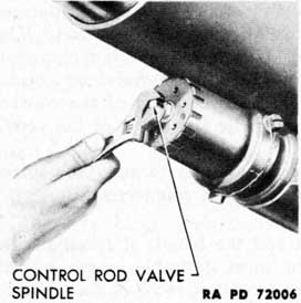
Figure 110 - Adjusting Control Rod Valve Spindle
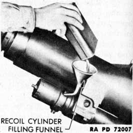
Figure 111 - Replenishing Fluid in Recoil Cylinder
The change-over to the new mixture will be performed only by ordnance maintenance personnel.
(3) To fill the recoil cylinder, proceed as follows:
(a) Elevate the gun to 25 degrees. Remove the recoil cylinder filling plug. Remove the control rod valve spindle adjustment screw and plate. Open the control rod valve by turning the squared end of the control rod valve spindle (fig. 110). Using the filling funnel, pour the blend of recoil and hydraulic oil in until it overflows from the filling valve (fig. 111). Remove the funnel and replace the filling plug.
(b) Elevate and depress the gun slowly a few times, finishing with the gun at 25 degrees elevation. Remove the filling plug again and, using the funnel, pour in liquid until full. Reset the control rod valve by screwing the control rod valve spindle down completely and then unscrewing it one-third turn. Replace the adjusting plate and screw. Replace the filling plug.
d. Recoil Cylinder Emptying. Depress the gun. Open the control rod valve. Remove the filling plug. Place a clean, dry pail or any other receptacle in position and remove the draining plug.
e. Recoil Cylinder Exercising.
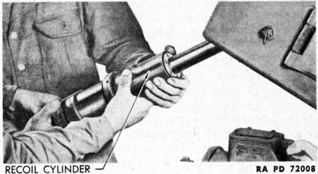
(1) The recoil cylinder piston rod will corrode and stick at the rear packing gland unless it is exercised frequently. Such sticking may result in severe damage to the weapon if the gun is fired. The recoil cylinder piston rod must be exercised weekly to insure its proper operating condition.
(2) Detach the recoil cylinder from the breech casing (par. 81 c). With the piston rod retaining pin held in the lugs on the front of
143
Figure 112 - Exercising Recoil Cylinder
the breech ring, pull the piston rod to its limit out of the recoil cylinder (fig. 112) and return it to its original position. Do this several times.
(3) Should the piston rod be corroded, it may be very difficult to break it free. In this case, assemble the recoil cylinder to the breech casing in the reversed position (recoil rod pointing toward gun muzzle). This will provide a means of holding the recoil cylinder without danger of crushing it Tap or apply pressure to the retaining pin to turn the rod on its own axis to break it free.
(4) After the piston rod has been freed, polish the corroded area with CLOTH, crocus, and oil lightly. Install the recoil cylinder.
NOTE: If the battery personnel cannot free the piston rod by the methods suggested, the mechanism should be referred to ordnance maintenance personnel for overhaul.
f. Care of Recoil Oil.
(1) A blend of 60 parts by volume of OIL, hydraulic, and 40 parts by volume of OIL, recoil, light, is used in the recoil mechanism. Below 20 F, a mixture of 50 percent OIL, recoil, light, and 50 percent OIL, recoil, special, will be used. Care must be taken not to use any liquid other than that prescribed. Water and other foreign matter must not be introduced into recoil mechanisms that use recoil oil.
(2) Recoil oil, hydraulic oil, or the correct mixture of these two oils must not be put into any container not marked with the name of the oil, nor left in open containers, nor be subjected to excessive heat, nor mixed with any other type of oil than those prescribed. The transfer of these liquids to containers not properly marked may result in the wrong liquid getting into the recoil mechanism, or in the use of recoil oil or the prescribed mixture being used for lubricating purposes.
144
(3) When putting the mixture into the system, it should be filtered through a piece of clean cloth as well as through the wire strainer of the filling funnel. Every precaution must be taken to prevent the introduction of water or grit into the mechanism, either in the mixture or through failure to clean thoroughly the connections and servicing equipment.
(4) Exposure of these liquids in an open can may result in the accumulation of moisture. Condensation in a container partly filled with oil or the mixture, or the pouring of any of these liquids from one container to another which has moisture on its inner walls, results in moisture being carried along into the recoil mechanism.
(5) If there is a possibility that the recoil oil, hydraulic oil, or the blend of these two oils may contain water, the suspected liquid should be tested by one of these methods:
(a) Fill a clean glass container of pint capacity with the liquid. Permit the liquid to settle. The water being heavier will sink to the bottom, if present. With the container slightly tilted, drops or bubbles will form in the lower portion. Invert the container and hold it to the light. Drops or bubbles of water, if present, may be seen slowly sinking in the liquid. If the liquid has a cloudy appearance, the cloudiness may be ascribed to particles of water.
(b) Another test for water is to heat the liquid to 212 F (boiling point of water) in a shallow pan. Water in the liquid will appear on the surface as minute bubbles. This test will disclose water not determinable by the settling test.
(c) Should either test show water, the liquid on hand should be turned in.
67. CARRIAGE.
a. General.
(1) The care and preservation of the carriage in service requires proper cleaning, strict observance of the lubrication program, tightening of loosened parts, and repair or replacement of broken parts. When traveling, it calls for proper attachment of the gun stay, secure locking of the drawbar, front and rear wheel axles, steering link securing clamp, outriggers, leveling jacks, and accessories in their positions on the carriage, the full protective use of metal and cloth covers, then proper adjustment of wheel bearings and brakes, and the correct inflation of tires.
(2) All bearing surfaces, revolving parts, springs, screw threads, gear teeth, and exterior parts must be kept as clean and free from dirt as possible. Special attention must be given exposed teeth and bearing surfaces. Cotter pins must be properly spread. Bolts, nuts, and screws must be tight and locked to prevent their coming loose.
(3) The carriage should receive a general inspection periodically.
145
(4) In adjusting, tightening, disassembling, and assembling the best available tools should be used. Care must be exercised that dirt, dust, or other foreign matter is not permitted to enter the mechanism.
CAUTION: The front and rear chassis compensating spring locks should remain locked during the removal of tires and wheels, and should not be unlocked until wheels and tires are replaced and leveling jacks are raised so that wheels are in solid contact with ground.
(5) Care must be exercised to detect any cutting or abrasion of the teeth of the elevating arc or other parts. Any deformation of this nature should be reported to the ordnance maintenance personnel for correction. Rust must not be permitted to accumulate on any part.
(6) When the carriage is to be stored, or is not to be used for more than a week, unpainted surfaces should be cleaned with SOLVENT, dry-cleaning, and coated with COMPOUND, rust-preventive, light.
(7) All lubricating fittings should be kept clean and, if necessary, a piece of wire may be used in cleaning out oil passages. Do not use a sliver of wood as it may splinter and clog the passage. Exercise care so as not to damage the interior of the fitting. In painting oil fittings, keep paint out of the openings.
(8) Remove drain plugs (there are two) and drain the chassis of the carriage as often as necessary to keep water from accumulating in the girder and the swivel body.
b. Equilibrator Adjustment.
(1) For proper operation of the remote control system, the equilibrators must be adjusted so that the effort required to elevate is the same as that required to depress the gun. Each equilibrator must be adjusted to the same degree to keep the pull from each equalized.
(2) Test the amount of effort required to elevate and depress the gun. If the effort to depress the gun is more than that required to elevate, adjust the equilibrators in this manner:
(a) Open both equilibrator covers. With the equilibrator rod bushing nut wrench, remove the equilibrator rod jam nuts from both rods. If the effort to depress the gun is more than that required to elevate, turn out the equilibrator rod bushing nuts; if the effort to elevate is the greater, turn in the bushing nuts. In tightening and loosening the nuts, be sure to adjust both exactly alike.
(b) When the adjustment is completed, lock both bushing nuts in position with their jam nuts. Close the end covers.
(3) The equilibrator cross bar and collar should be oiled frequently with OIL, engine, SAE 10, to prevent rusting. The trunnion bearings should be checked to make sure they are working smoothly and efficiently. The insides of the cases, springs, spacers, and other
146
parts should be greased; see paragraph 87 for instructions for disassembly and assembly.
c. Elevating Rack and Pinion.
(1) The teeth of the elevating rack and pinion require little lubrication, but as a protection against rust, they must be covered with a thin coating of oil. Under normal conditions, dust and grit will adhere to this oily film and cause wear of both rack and pinion; consequently, the teeth must be thoroughly cleaned and relubricated daily.
(2) If a considerable amount of dust or sand is present, the teeth should be wiped dry before the gun is operated, situation permitting, and then be relubricated after the action is over. With the surfaces dry, there is less wear than when they are coated with lubricant contaminated with sand.
(3) Check the elevating mechanism for evidences of backlash. Report to the ordnance maintenance personnel for correction. Backlash will result in excessive muzzle whip and inaccuracies in firing.
d. Traversing Mechanism. Check the traversing mechanism for evidences of backlash. Report to the ordnance maintenance personnel for correction. Backlash will result in incorrect indicator readings and inaccuracies in firing.
e. Front and Rear Chassis Compensating Spring Lock and Cover.
(1) When engaging the front and rear chassis compensating spring locks in the toothed chassis locking arcs when lowering and raising the weapon, care should be taken to insure that the lock is fully engaged and alined with one of the notches in the arc. Excess pressure on the lock handle when teeth are not engaged properly will result in the shearing of the taper pins which secure the handle to the lock spindle.
(2) In cold weather operations, water and moisture seeping into the housing of the axle lock will, upon freezing, prevent operation of the lock. The lock should be kept well lubricated with OIL, engine, SAE 10, or OIL, lubricating, preservative, light. The top of the lock shank and housing should be heavily covered with grease to prevent water from seeping into the housing. The opening between the housing and the lock should be greased each time the carriage is raised or lowered, as the movement of the lock will break the grease seal. An improvised cap may be made to prevent moisture from collecting in the housing.
(3) All carriages are required to be modified by the addition of chassis clips and web straps, to prevent the front and rear chassis compensating spring locks from becoming accidentally disengaged from the chassis locking arcs. These straps should secure the lock handles in locked position at all times, except when the lock handle is used to unlock the axles.
147
Figure 113 - Front Firing Pedal - Proper Amount of Travel
Figure 114 - Front Firing Pedal Stop and Nut - Adjustment
Figure 115 - Rear Firing Pedal - Adjustment
f. Firing Mechanism.
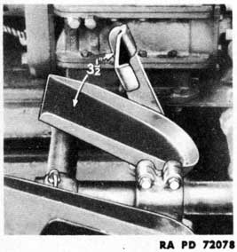
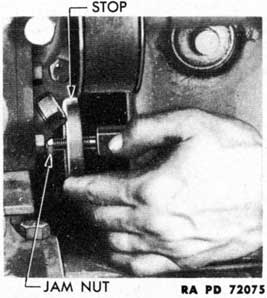
(1) To ADJUST FRONT FIRING PEDAL. For sufficient movement for proper functioning, the front firing pedal when released should be 3 1/2 inches from the inner footrest (fig. 113). To adjust, loosen the jam nut on the inner front firing pedal link and rotate the front pedal link firing stop (fig. 114). When adjustment has been made, tighten the jam nut.
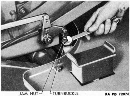
(2) To ADJUST REAR FIRING PEDAL. The rear firing pedal should have no free travel. To adjust, loosen the jam nut on the firing mechanism turnbuckle. Turn the turnbuckle up (fig. 115) until
free travel is felt in depressing the pedal. Then turn the turnbuckle down until the free travel of the pedal is eliminated. Tighten the jam nut.
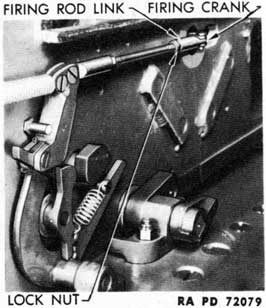
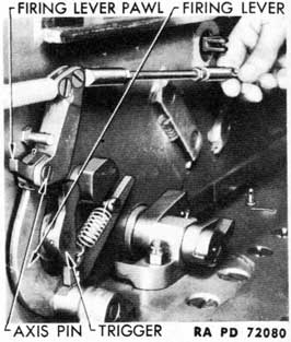
(3) To ADJUST BREECH CASING FIRING MECHANISM FOR SINGLE FIRE. If gun will not single fire, adjust the clearance between the firing lever pawl and the trigger. The pawl pivots on an axis pin mounted through lugs on the firing lever (fig. 117). To adjust, disconnect the front firing rod link from the firing crank by removing the cotter pin and axis pin. Loosen the firing rod link lock nut. Screw the firing rod link in or out to adjust the clearance. Tighten the lock nut. Connect the firing rod link to the firing crank.
g. Level Assemblies. Check the level assemblies on the base plate of the top carriage. Place the weapon in firing position on a flat surface. Level the weapon by means of the level assemblies. Traverse the weapon 180 degrees, check the levels, and relevel as necessary. Traverse the weapon 360 degrees, checking the levels at each 90 degrees. If the levels do not indicate levelness during the full traverse of the weapon, check the levelness of the weapon in full traverse with a gunner's quadrant placed on the machined section of the breech casing. If the levels are at fault, or if the weapon will not remain level in a full traverse, report the matter to the ordnance maintenance personnel.
h. Pneumatic Tires and Tubes.
(1) The pressure to be maintained in the tires is 45 pounds per
149
square inch. To obtain maximum mileage, the air pressure in the tires should be checked prior to operations and thereafter left alone unless there is a loss of air pressure. Bleeding of air from the tires results in an increase of the flexing of the tire side walls which increases the danger of failure.
(2) Remove all foreign substance from the rubber, being especially careful to keep tires as free from oil and grease as possible. Oil and grease have a deteriorating effect upon rubber.
i. Care of Electric Brakes. Proper attention must be given the electrical brake system to insure proper functioning. It is essential that the using arm personnel has knowledge which will permit the detection and correction of malfunctions which may occur during traveling. This knowledge will also permit the best possible service from this equipment. The following information and that contained in paragraph 57 a through d will prove helpful:
(1) WIRING AND CONTROLLER. Check the wiring and the controller before examining the brakes. Check for poor connections and partly broken or worn wires. Test the battery of the prime mover to see that it is sufficiently charged to turn over the starting motor. When brakes are new, several applications must be made before maximum efficiency is obtained.
(2) CHECK CURRENT AT ELECTRIC BRAKES.
(a) Check current of the brakes, using the ammeter furnished as an accessory. Disconnect one brake wire only. Connect one side of the ammeter to the brake, the other side to the terminal of the live wire that was removed from the brake. Leave the other brakes in the circuit. Take a reading; it should not be less than 2.2 amperes. If this amount of current is not flowing through each brake, proper operation will not be obtained.
(b) Check current consumption of each of the brakes, one at a time, leaving the others in circuit. The readings should not vary more than 0.5 ampere. In case there are greater variations, check all connections for poor contacts or broken wires. As the tests are completed, remove the ammeter from the circuit and connect the live wires to the brake terminals.
(3) CHECK DRY CELL BATTERY. Check the battery used to actuate the electric brakes when the carriage breaks away from the prime mover. The using arm personnel must make certain that this battery will produce sufficient current to actuate the brakes at all times. All wiring and switches must function correctly.
(4) FACING OF MAGNET. The facing of the magnet may become glazed. This is due to some foreign substance embedding itself into the material, resulting in a polished surface. If the facing cannot be roughened with coarse CLOTH, abrasive, aluminum-oxide, notify ordnance maintenance personnel.
(5) STOP LIGHTS. Stop lights must not be connected into the
150
brake circuit. This changes the amount of current which passes through the controller, resulting in weak or grabbing brakes.
(6) BEARINGS AND WHEELS. Worn bearings or loose wheels will cause erratic action of the brakes and will be evidenced by the wide track the pole faces of the magnets make on the armatures. The roller bearings must be adjusted (par. 88 d); broken or badly worn bearings must be replaced. Notify ordnance maintenance personnel.
(7) Notify ordnance maintenance personnel when brake lining is worn out or has become greasy, brake bands have become distorted, brake drums are out of round, or other conditions are found, the corrective measures for which are beyond the scope of using arm personnel.
j. Adjustment of Brakes.
(1) Remove wheel, hub, and drum assemblies, and clean out accumulated foreign substance. See that shoes move freely on backing plate and are seated against the anchor pin.
(2) Reinstall hub and drum assemblies and loosen nut on secondary shoe equalizer just enough to allow equalizer to turn.
(3) Turn the equalizer in direction the wheel revolves when in forward motion until brake has considerable drag.
(4) Turn brake drum so that slot for feeler gage is near equalizer and insert 0.010-inch feeler gage between drum and brake lining. Then turn the equalizer in opposite direction very slowly until only a slight drag is felt on feeler gage. Tighten the equalizer, lock nut, and recheck clearance to see that equalizer has not moved while tightening lock nut. Use a 3/16-inch wrench on brake equalizer and a 9/16-inch wrench on lock nut.
(5) With the secondary shoe properly adjusted, remove the small metal cover in the backing plate and expand the adjusting screw until brake drags slightly. Then release the adjusting screw until only a slight drag is felt on a 0.010-inch feeler gage, placed at the center of the primary shoe.
NOTE: Be sure to replace brake backing plate adjusting hole covers to prevent entry of foreign substances.
k. Lighting.
(1) The lighting fixtures on the rear of the carriage are equipped for both service lighting and blackout lighting. The change-over from service to blackout lighting, and from blackout to service lighting is made by lifting the small cover on the right side of the rear end of the chassis and turning the slot to indicate "S" (service) or "BO" (blackout).
(2) STOP AND TAILLIGHT LAMP REPLACEMENT. Remove the two lamp cover retaining screws. Remove the cover. Lamp units can be withdrawn straight back out of their sockets in the lamp housing.
151
l. Care of Canvas. To prevent formation of damaging mildew during periods of storage, shape out and air the canvas cover for several hours at frequent intervals. Repair without delay any loose grommets or rips in the canvas; failure to make immediate repairs may allow a minor defect to develop into major damage. Mildewed canvas is best cleaned by scrubbing with a dry brush. If water is necessary to remove dirt, it must not be used until mildew has been removed. If mildew has been present, examine fabric carefully by stretching and pulling for evidence of rotting or weakening of fabric where mildew has been. If fabric shows indication of loss of tensile strength, it is probably not worth retreatment. Oil and grease can be removed by scrubbing with issue soap and warm water. Rinse well with clear water, and dry.
CAUTION: At no time is gasoline, or solvent to be used to remove oil or grease spots.
68. CLEANERS AND PRESERVING MATERIALS.
a. The following cleaners, abrasives, and preservatives are for use with this materiel. See TM 9-850 for detailed information.
PRIMER, synthetic, refinishing
PRIMER, synthetic, rust-inhibiting
THINNER, for synthetic enamels
THINNER, paint, volatile mineral spirits
VARNISH, shellac
70. MISCELLANEOUS MATERIALS AND TOOLS.
a. The following miscellaneous materials and tools are required for use with this materiel. See Table of Allowances and TM 9-850 for detailed information.
BRUSH, varnish, oval (1 7/8-in.)
CHALK, white, railroad, 1-in. x 4-in.
KNIFE, putty, 1 1/4-in. type IV
NEEDLES, sacking
PALM, sailmaker's
TWINE, jute
b. The bristles of brushes are subject to attack by moths. Brushes in storage should be protected by NAPHTHALENE balls.
c. Brushes used for painting after being thoroughly cleaned with THINNER, paint, volatile mineral spirits should be laid flat on a horizontal surface (not in water).
71. WASHING.
a. Serious damage to ordnance materiel, in many cases requiring repair and replacement of component parts of sighting equipment, fire control instruments, weapons, and carriages, has frequently resulted from the use of water, steam, or air from a high-pressure hose for cleaning purposes. For this reason, operating personnel is cautioned to prevent water, dirt, or grit from being forced into any part of the gun or carriage when using water, steam, or air under pressure for cleaning.
b. Under no circumstances will a hose, either normal-pressure or high-pressure, be used in cleaning any sighting equipment or any fire control instruments. Before washing, take off removable sighting equipment from the materiel to be cleaned. In cases where it is not removable, take care to cover the parts properly.
153
72. PAINTING.
a. General.
(1) Ordnance materiel is painted before being issued to the using arms and one maintenance coat per year will ordinarily be ample for protection. With few exceptions, this materiel will be painted with ENAMEL, synthetic, olive-drab, lusterless. The enamel may be applied over old coats of long-oil enamel and oil paint previously issued by the Ordnance Department if the old coat is in satisfactory condition for repainting.
(2) Paints and enamels are usually issued ready for use and are applied by brush or spray. They may be brushed on satisfactorily when used unthinned in the original package consistency, or when thinned no more than 5 percent by volume with THINNER, for synthetic enamels. The enamel will spray satisfactorily when thinned with 15 percent by volume of this thinner. (Linseed oil must not be used as a thinner since it will impart a luster not desired in this enamel.) If sprayed, it dries hard enough for repainting within 1/2 hour and dries hard in 16 hours.
(3) Certain exceptions to the regulations concerning painting exist. Fire control instruments, for instance, which require a crystalline finish, will not be painted by the using arms.
(4) Complete information on painting is contained in TM 9-850.
b. Preparation for Painting.
(1) If the base coat on the materiel is in poor condition and it is desirable to strip the old paint from the surface rather than to use sanding and touch-up methods, it will be necessary to apply a primer coat after the old finish has been removed.
(2) PRIMER, synthetic, refinishing, should be used on wood as a base coat for synthetic enamel or as a second coat over PRIMER, synthetic, rust-inhibiting. It may be applied either by brushing or spraying. It will brush satisfactorily as received, or after the addition of not more than 5 percent by volume of THINNER, for synthetic enamels. It will be dry enough to touch in 30 minutes, and hard in 5 to 7 hours. For spraying, it may be thinned with not more than 15 percent by volume of THINNER. Lacquers must not be applied to the PRIMER, synthetic, refinishing, within less than 48 hours.
(3) PRIMER, synthetic, rust-inhibiting, for bare metal, should be used on metal as a base coat. Its use and application are similar to that outlined in step (2), above.
(4) The success of a job of painting depends partly on the selection of a suitable paint, but also largely upon the care used in preparing the surface prior to painting. All parts to be painted should be free from rust, dirt, grease, kerosene, and alkali, and must be dry.
c. Painting Metal Surfaces.
(1) Metal parts may be washed in a liquid solution, consisting of 1/2 pound of SODA ASH in 8 quarts of warm water, then rinsed
154
in clean water and wiped thoroughly dry. Wood parts may be treated in the same manner but the alkaline solution must not be left on for more than a few minutes and the surfaces should be wiped dry as soon as they are washed clean.
(2) When artillery is in fair condition and only marred in spots, the bad places should be touched with ENAMEL, synthetic, olive-drab, lusterless, and permitted to dry. The whole surface should then be sandpapered with PAPER, flint, class B, No. 1, and a finish coat of ENAMEL, synthetic, olive-drab, lusterless, applied and allowed to dry thoroughly before the materiel is used.
(3) If the equipment is in bad condition, all parts should be thoroughly sanded with PAPER, flint, class B, No. 2, given a coat of PRIMER, synthetic, refinishing, and permitted to dry for at least 16 hours. Sandpaper with PAPER, flint, class B, No. 00, wipe free from dust and dirt, and apply a final coat of ENAMEL, synthetic, olive-drab, lusterless. Allow the materiel to dry thoroughly before it is used.
d. Paint as a Camouflage. Camouflage is now the major consideration in painting ordnance materiel, with rust prevention secondary. The camouflage plan at present employed utilizes color and freedom from gloss.
(1) COLOR. Materiel is painted with ENAMEL, synthetic, olive-drab, lusterless, which was chosen to blend in reasonably well with the average landscape.
(2) GLOSS. The new lusterless enamel makes the materiel difficult to see from the air or from great distances over land. Materiel painted with ordinary glossy paint can be detected more easily and at greater distances.
(3) PRESERVING CAMOUFLAGE.
(a) Since continued friction or rubbing will smooth the surface and produce a gloss, it must be avoided. The materiel should not be washed more than once a week. Care should be taken to see that the washing is done entirely with a sponge or a wiping cloth. The surface should never be rubbed or wiped, except while wet, or a gloss will be developed.
(b) It is not desirable that materiel painted with lusterless enamel be kept as clean as when glossy paint was used. A small amount of dust increases the camouflage value. Grease spots should be removed with SOLVENT, dry-cleaning. Whatever portion of the spot cannot be so removed should be allowed to remain.
(c) Continued friction of wax-treated tarpaulins on the sides of the materiel will also produce a gloss. It should be removed with SOLVENT, dry-cleaning.
(d) Tests indicate that repainting will be necessary once yearly
155
in the case of the olive-drab and twice yearly in the case of the blue-drab enamel.
e. Removing Paint.
(1) After repeated paintings, the paint may become so thick as to scale off in places and present an unsightly appearance. If such is the case, remove the old paint by use of a lime-and-lye solution or REMOVER, paint and varnish. It is important that every trace of lye or other paint remover be completely rinsed off and that the equipment be perfectly dry before repainting is attempted. It is preferable that the use of lye solutions be limited to iron or steel parts.
(2) If used on wood, the lye solution must not be allowed to remain on the surface for more than a minute before being thoroughly rinsed off and the surface wiped dry with wiping cloth or waste. Crevices or cracks in wood should be filled with putty and the wood sandpapered before finishing. The surfaces thus prepared should be painted according to the directions given previously.
f. Painting Lubricating Devices. Oil cups, grease gun fittings, oilholes, and similar lubricating devices, as well as a circle about 3/4 inch in diameter at each point of lubrication will be painted with ENAMEL, synthetic, gloss-red, in order that they may be readily located.