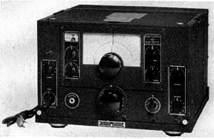
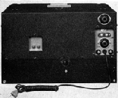
RBH RADIO RECEIVING EQUIPMENT
Use.-Ship-shore: CW, MCW, and voice, by phones or loudspeaker. * Frequency range.-300 to 1200 and 1700 to 16000 kc. in five bands. Power required for operation.-115/1/50-60, 70 watts. * Allowable variation in voltage, +- 10 percent. Description.-The Model RBH radio receiver is a 10-tube * table mounted superheterodyne. Its circuit consists of one stage of RF * amplification, first detector, HF oscillator, two stages of IF amplification at 1560 kc., diode detector, noise peak limiter, CW oscillator, and two stages of resistance coupled audio amplification. Associated with the AVC is a signal strength meter calibrated in S-units from 1 to 9 and in db. above S-9 from 0 to 40 db. A crystal filter, having both selectivity and phasing adjustments, is connected between the first detector and the first IF amplifier tubes. A built- in power supply supplies all voltages required by the receiver. A headphone jack is mounted on the panel and a pair of loudspeaker terminals are located on the rear of the chassis. When the headphone is plugged in the loudspeaker circuit is opened. * All radio-frequency transformers and their associated trimmer capacitors are mounted in a cast aluminum catacomb having 15 shielding compartments. * Each RF transformer and its associated trimmer capacitors is mounted on a low loss bakelite base fitted with contact pins which protrude from the coil catacomb. Manipulation of the band change knob slides the coil catacomb across the width of the chassis causing the contact pins of each set of RF transformers to engage, in turn, with contact springs mounted on the receiver chassis. A dial with 5 scales is calibrated in accordance with the frequency response of the 5 bands. The particular band in use is indicated by the tip of the pointer, which moves radially as the band selector knob is turned. * In addition to the frequency-calibrated scales, an auxiliary numerical dial is employed. This dial has 100 divisions and makes 10 revolutions while the tuning capacitor rotates 180 degrees; it is direct reading to 1 part in 1,000. The power-supply circuits provide 6.3 volts at 3.15 amperes for the heater circuit of the receiver and 240 volts * at 70 * milliamperes for the B supply. A two- section filter is employed. The loudspeaker * chassis has a nominal diameter of 8 inches and is of the table mounted type. A coupling transformer having an input impedance of 5,000 ohms is provided to match the voice coil and the receiver output impedances. The antenna-input circuit is suitable for use with a single-wire antenna, a balanced feed line or a low impedance concentric transmission line. The impedance of the antenna or transmission line at the receiver input terminals should not be less than 70 ohms. The antenna input terminals are located at the rear of the chassis near the center. Two insulating binding posts are provided together with a short length of flexible lead permanently attached to the receiver chassis. By means of this lead, either input terminal may be grounded to the chassis if required. It is recommended that the receiver be permanently grounded; the ground wire may be attached directly to the input terminal which is connected to the chassis. The dimensions of the single-wire antenna system are not at all critical; the recommended minimum over-all length of antenna and lead-in is 50 feet; the recommended maximum over-all length is 200 feet. TECHNICAL FEATURES Tube complement | Number | New type Function | of tubes | No. RF amplifier | 1 | 6K7 First detector | 1 | 6J7 HF oscillator | 1 | 6J5 First IF amplifier | 1 | 6K7 Second IF amplifier | 1 | 6K7 First audio amplifier | 1 | 6F8G Automatic vol. control | | Second Detector | 1 | 6C8G Limiter | | CW oscillator | 1 | 6J7 Second audio amplifier | 1 | *6V6GT Rectifier | 1 | 5Z3 Total 10Type of receiver.-Superheterodyne. Type of reception.-CW, MCW, and voice by either phones or loudspeaker. Output impedance.-600 ohms * for phones and 5,000 ohms for the loudspeaker. Power output.-12 mw. * for phones and 2 * watts of undistorted power for the loudspeaker. Loudspeaker * circuit is opened when the phone jack is inserted. Antenna.-Single wire or low impedance transmission line. Radiation frequencies.-RBH: Safe-all, only when used with preselector. Band coverage: Band: Frequency rang in kc. 1 300 to 600 2 600 to 1200 3 1200 to 3900 4 3900 to 8000 5 8000 to 16000Weights, dimensions, and Navy type numbers: Unit | Navy type | Height | Width | Depth | Weight | | Inches | Inches | Inches | Pounds Radio receiver | CNA-46144 | 12 13/32 | 17 3/16 | 11 1/4 | * 55 Loudspeaker | CNA-49106 | | | | 11 One set spare parts | | | | | 19 Total weight of | | | | | the equipment | | | | | * 85Sensitivity.-For 6 mw. output power. MCW and CW, 10 microvolts or better for all frequencies. * Indicates differences between RBH and RBH-1. See appended paragraph on RBH-1.
RBH-1 RADIO RECEIVING EQUIPMENTThe chief difference between the Models RBH and RBH-1 lies in the fact that RBH-1 has an added stage of RF for preselection and no loudspeaker is supplied. The Model RBH-1 is then an 11-tube superheterodyne instead of a 10, and, although provided with terminals for a loudspeaker the connection is in parallel and is not affected by the insertion of the phone-plug.All radio-frequency transformers and their associated trimmer capacitors are mounted in 2-cast aluminum catacombs having a total of 20 shielding compartments. Each HF transformer and its associated trimmer capacitors is mounted on a low loss bakelite base fitted with contact pins which protrude from the coil catacomb. Manipulation of the band change knob slides the coil catacombs across the width of the chassis causing the contact pins of each set of HF transformers to engage, in turn, with contact springs mounted on the receiver chassis. The band in use is indicated by the band designation that is uppermost on the knob as it is rotated. TECHNICAL FEATURES Power required for operation.-60 watts. Power supply circuits provide 6.3 volts at 3.45 amperes for the heater circuits and 290 volts at 55 milliamperes for the B supply. Tube complement.-The additional stage of RF takes a 6K7 tube and the second audio amplifier is a 6K6 GT/G tube. Output impedance.-600 ohms. Output power.-0.3 watts. Radiation frequencies.-Safe-all. Weights, dimensions, and Navy type numbers: Unit | Navy type | Height | Width | Depth | Weight | | Inches | Inches | Inches | Pounds Radio receiver | CNA-46188 | 12 13/32 | 17 3/16 | 11 1/4 | 74 Mounting base | CNA-49125 | Included in above | | 5 3/4 One set spare parts | | | | | 20 Total weight of | | | | | the equipment | | | | | 99 3/4 REFERENCES:The information enclosed here is excerpted from:Catalogue of Naval Electronic Equipment-April 1946- NavShips 900,116.
|


