A Catalog of Electronics Aboard USS Pampanito
Radio Communications:In the Radio Room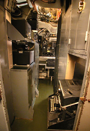 The RAK-6 radio was used to receive Morse code (CW) messages at low & medium frequencies (15-600 KC), less often it was used for to receive voice. This radio was usually paired up with an RAL to cover a wider frequency range. The radio does not have a tuning dial, but can be tuned by matching a signal generated by the LM-18 Frequency Meter. Charts of settings for commonly used frequencies made this quicker than it might sound. RAK-6 Serial #1539 and its separate 110 VAC power supply are original to Pampanito and are in good working order. The RAK-6 radio was used to receive Morse code (CW) messages at low & medium frequencies (15-600 KC), less often it was used for to receive voice. This radio was usually paired up with an RAL to cover a wider frequency range. The radio does not have a tuning dial, but can be tuned by matching a signal generated by the LM-18 Frequency Meter. Charts of settings for commonly used frequencies made this quicker than it might sound. RAK-6 Serial #1539 and its separate 110 VAC power supply are original to Pampanito and are in good working order.The RAK also has a National Electrical Machine Shops (NEMS) coupler unit, serial #3, for use with the CRV-66096 submarine loop antenna. This is the low frequency loop (donut shaped) antenna between the periscope shears. The RAL-6 radio was used to receive Morsecode (CW) or voice messages at frequencies 300 KC- 23 MC. This radio is very similar to the RAK, but in a different frequency range. RAL-6 serial #115 and its separate 110 VAC power supply are original to Pampanito and are in good working order. The RBH-2 radio was used as a general purpose receiver working well to receive voice (AM) as well as Morse code (CW). It covered 300 KC - 1.2 MC, and 1.7 MC - 16 MC in five bands. It could be tuned with a calibrated dial. A working replacement is aboard. The TBL-7 is the main transmitter for the boat, it could be used to send Morse code (CW), or voice (AM). It can be used for long distance communications. The power output depending on the frequency and mode of operation and varied from 50-200 watts.
The 50064 Speech Input Equipment is used to generate AM voice on the TBL. Handsets were installed in the radio room and conning tower. Serial # 260 is original to boat and in good working order. The handset in the conning tower is missing and we are seeking a replacement. The LM-18 Frequency Meter is used to accurately tune the operating frequencies of the radios aboard. Serial # 1304 is original to the boat and in good working order.
An AN/ARC-4 , AM, VHF radio was primarily used to send and receive messages to aircraft, but also short range communication with other ships. This was used for "Dumbo"duty when the submarine waited off the coast of enemy territory to rescue downed airmen. During Pampanito 's summer of 1945 refit the AN/ARC-4 was replaced with an SCR-624B (aka SCR-522 ) VHF transceiver. This is a more reliable radio than the AN/ARC-4 and uses a small AC power supply instead of a motor generator for power. A working replacement SCR-624B is aboard at this time, but we are still trying to figure out the correct type of shock mount. The ECM Mark II cipher machine was used to encrypt outgoing messages and decrypt incoming messages. When sending a message,the text was typed on this machine by an officer and the ECM Mark II printed out a cipher text version of the message on a strip of paper. This was then handed to a radio operator that used Morse code to send the message. The reverse process was used to receive a message. In The Crew's MessThe RBO radio was used as a entertainment receiver. Depending on the conditions, radio broadcast programs could be heard from around the world. A working replacement is aboard.Speakers with a built in amplifier are located in several compartments to listen to the RBO radio. The 49131-B Speaker Amplifier . Serial# 6155 is in the crew's mess (works), serial #6042 is in the wardroom (works), serial #5856 is in the forward torpedo room (condition unknown), and serial # 1304 in the aft torpedo room (needs work). All are original to the boat. Radar:Radars send powerful high frequency (usually microwave) pulses out and then measures the signals that bounce off other objects and return to the radar. This provides a way to measure how far the object is (its "range".) By rotating the radar antenna, the angle (or "bearing") of the target can be determined.The SJ-1 radar was used to locate aircraft and other ships. All the radars were also used to take bearings and range of the shore for navigation as well. Serial # 12 is original to the boat and appears to be complete, but has not had any restoration effort. The training motor and control are restored to operation. The ST radar was used to determine the range of a target ship. Its antenna is located inside a periscope. Serial # 166is original to the boat and appears to be complete, but has not had any restoration effort. The SV radar was used to locate aircraft and other ships. This unit was installed as a replacement for the more primitive SD radar in July of 1945. Serial # 28 is original to the boat and appears to be complete, but has not had any restoration effort. At least one piece of its waveguides where disconnected, but have been retained. The hydraulic antenna mast and training motor have been restored and are operational. The ABK-1 IFF (Identification Friend orFoe) transponder was used to identify Pampanito as friendly to other compatibly compatibly equipped forces. Two were installed, one being the backup unit if the first one failed. The original transponders with all their supporting equipment and mounting brackets were removed in 1955. We have replacements aboard and are seeking some of the auxiliary components necessary to restore this system. The BN IFF (Identification Friend or Foe) interrogator/responder was used to identify aircraft or other boats with compatible systems as friendly. Its information is displayed on the radar displays. The original with its all its supporting equipment and mounting brackets were removed in 1955. We have a replacement aboard, and we are seeking some of the needed auxiliary components. The AN/APR-1 Radar countermeasures was used to receive radar signals from other ships or aircraft. These were then analysed using the AN/SPA-1. AN/APR-1 Serial #255 with tuning units TN-1 serial # 30, TN-2 serial # 158, TN-3 serial # 174 are in the control room. They are original to the boat and appear to be intact, but have not had any restoration effort. The radar counter measures antenna is intact on the boat, its condition is unknown. The AN/SPA-1 Radar countermeasures was used to identify radar signals from other ships or aircraft. Serial # 519 in the control room is original to the boat and appears to be complete, but has not had any restoration effort. Its condition is unknown. Sonar:Sonar consists of active and passive systems. A passive system like the JP-1 is used to listens to underwater sounds made by other vessels. It has the advantage of not making any noise that can be heard by an enemy ship, but can only detect objects that are making noise. An active sonar, such as the WCA, transmits sound waves through the water and measures the time it takes for the return signal. This is much like an underwater radar. This allows taking both the bearing and range, but also makes sound that the enemy can detect. The JT sonar was used to passively listen for other ships and boats. The JT sonar was installed to replace the JP-1 sonar in July of 1945. It is an upgrade to the JP that included electronic outputs of the target bearing that could directly input into the TDC. We have a replacement JT master transmitter that needs restoration before being put on the boat. We are missing the training mechanism, talkback unit and other ancillary gear. A replacementJP-1 hydrophone is installed. The WCA sonar was used to locate other ships and boats. Serial # 67 is original to the boat and appears to be complete,but has not had any restoration effort. Its underwater transducers, JK/QC,QB are thought to be installed and are protected by blanking plates. The Submarine Signal Corporation Depth Sounder was used to determine how deep the water was beneath the keel. The indicator/amplifier unit is in the control room and is configured as part of the WCA sonar. It is original to the boat and appears intact, its condition is unknown. We do not know if there is an NM transducer installed in the ballast tank. The Bathothermyograph CBT40131 was used to chart the temperature of the water. This information could be used to find changes in temperature that would bend sound waves that were used by the enemy to locate the boat. This is not an electronic device, but rather uses the change in volume that occurs in a contained gas to indicate the change in temperature. The unit in the control room is original. It appears intact, but its condition is unknown. Navigation:The DAS-3 LORAN is in the control room. It was used to locate the boats position when close to shore based transmitter stations. A replacement is installed in control room. It powers up, but otherwise the status is unknown since the LORAN signals it uses are no longer transmitted. We would like to simulate these signals with a computer for testing, or find one of the WW II era testing devices.The Bendix Pit Log was used to determine Pampanito's speed through the water. The master controller is in the forward torpedo room and appears intact, but its condition is unknown. It has had two non-standard stuffing tubes added to its front. The indicators in the Conning Tower and Control Room have been restored. Piping and hoses to the pit sword are missing. The Bendix Dummy Log was added in summer of 1945 to emulate the function of the ships Bendix Master Log in case of casualty to the Master Log. The Dummy Log Speed control in the Maneuvering Room and the Dummy Log Distance Transmitter behind the gyro control panel in the Control Room have been restored and are operational.
The Arma Mark VII Main Gyrocompass is an inertial guidance system used to determine the movements of the boat when underwater. The unit we have in the control room is original to the boat, and has undergone restoration.The effort to complete its restoration is nearly done. Arma Mark IX Auxiliary Gyrocompass - Its condition is unknown, but it appears to be intact. The Arma Mark V Dead Reckoning Analyser Indicator (DRAI) appears to be intact, but the condition is unknown (but not great). This takes the input from the Gyrocompass and the Log and uses it to calculate the Latitude and Longitude of the boat. It provides the source signals to the Dead Reckoning Tracers. It is original to the boat. The Arma Mark IIV, Class 3 Dead Reckoning Tracers (DRTs) in control room and the conning tower (serial # 7187) were used to plot and keep track of the boats position and the positions of other ships. They appear intact, their condition is unknown. Fire Control:The Arma Mark III, Mod 5 Torpedo Data Computer in the conning tower is original to the boat and restored to full operation. It is an electromechanical, analog computer used to aim the torpedoes. The Gyro Indicating Regulating Setters (GISR) serial # 284 in the forward torpedo room and # 283 in the aft torpedo rooms are intact. Both are operational, synching and tracking the TDC.
The Target Designation System displays the bearing and range of a target. It gets input from the gyrocompass, TBTs, sonars and radars. The Depth Charge Direction Indicator (DCDI) is missing from the conning tower. This was used to determine in which direction depth charges where exploding. We have the blast phones for the system, but they are not wired. The Depth Charge Range Estimator (DCRE) is missing from the conning tower. This was used to estimate how far away depth charges where exploding. Interior Communications:The I.C. systems of the submarine consist of about 24 circuits. With few exceptions, they are supplied with power through the I.C. switchboard located in the control room. They are used to communicate between people on the boat, remotely monitor or control equipment, provide alarms and other communications functions. Most of the fire control and navigation equipment is also supplied by the I.C. system. Some of the more important circuits are listed here: The general announcing system is comprised of two voice communications circuits, one-way (1MC) and two-way (7MC). The same amplifier equipment is used for both circuits. Generally, one channel is used for the 1MC and one for the 7MC, but in an emergency both circuits may be operated through either of the two individual amplifier channels. The 1MC/7MC serial # 1004 is original to the boat. Its electro-mechanical signal generators are in good working order. Amplifiers have worked in the recent past, but are not currently working. A modern Bogen amplifier is hidden from view and is used with the original signal generator.The alarm system is made up of three alarms: the diving alarm, collision alarm and the general alarm. The diving alarm is a series of motor driven alarms located throughout the submarine with a distinctive "ah-oo-ga" sound. Both the general alarm and the collision alarm are produced by signal generators located in the 1MC/7MC amplifier stack and sound through 1MC speakers or horns in each compartment. The general alarm is a gong sound at 100 beats a minute that is sounded for ten seconds. The collision alarm is a rising frequency siren signal. The sound powered phone system is a telephone system in which the power comes from the sound of the voice. Vibrations from the voice cause a diaphragm to vibrate. Attached to the diaphragm is a delicate needle, or armature, that is surrounded by a fine wire coil held in place by a magnet. The movement of the armature inside the coil induces current which is transmitted through the line to a receiver. The receiver is constructed exactly like the transmitter. The current from the transmitter passes through the coil on the receiver and causes the diaphragm to vibrate and reproduce the speaker's voice. The system is divided into two circuits, the XJA (handset) used for routine ship's service communication, and the JA (headset) used on all battle control stations. The telephone call system consists of hand cranked signal generators located in each compartment and require no supply voltage. Often refereed to as "growlers" each unit consists of a selector rotary switch used to select the compartment desired and a small speaker that "growls" on the receiver unit to notify the compartment of an incoming call. It is a separate complete circuit and is not connected to the phone systems. Other I.C. systems include the Engine governor control and tachometer system, Engine order control system, Lubricating oil and water temperature alarm system, Shaft revolution indicator systems, Motor order telegraph system, Rudder angle indicator system, Bow and stern plane angle indicator system, Auxiliary bow and stern plane angle indicator system, Main ballast indicator system, Hull opening indicator system, Bow plane rigging indicator system. Other:The Hydrogen Detector type N.H.D., Type No. 3, Cities Service Oil Co. was used to detect the build up of explosive hydrogen from the main batteries. It is located in the control room. It appears to be intact, but its status is unknown. Its large multiconductor cable that runs aft was cut and reused during the reserve period as part of the simulator system and will need restoration.The Type 51011 Torpedo Battery Charger withType 510008 Controller were used to charge the Mark 18 torpedo batteries. There are two sets in the forward torpedo room and one set in the aft torpedo room, all original to boat. They appear intact except for knobs, but their condition is unknown. The Type 5102 Hydrogen Burning Wire Controllers , serial # 4439986B81 in the forward torpedo room and serial # 443986A65 in the aft torpedo room were used to avoid the buildup of explosive hydrogen gas while charging Mark 18 torpedoes. They are original to the boat and appear intact, but their condition is unknown. Test Equipment:All the test equipment that was normally aboard was missing, we have found replacements for some of this equipment. This list below is probably not complete.
A list of equipment known to be missing may be found in our wish list.
|
