1. Determine, before making any Line Space Lever adjustments, that the trouble is not in the Variable mechanism (see Variable). Variable mechanism parts should be properly lubricated. Generally, under-throwing or over-throwing is caused by improper positioning of Detent Roller in Ratchet Teeth.
2. ADJUSTMENTS:
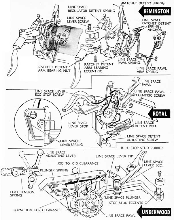
a. Determine if there is over-throw or under-throw of the platen after the line spacing has been completed by movement of the platen while holding the Line Space Lever engaged fully. The Detent Roll should seat between two teeth of the ratchet when the Line Space Lever has been
engaged fully by movement to the right, and the Line Space Pawl is seated on the ratchet tooth fully without excess movement of the ratchet. Adjustment may be made with the Ratchet Detent Arm Bearing Eccentric after loosening Ratchet Detent Arm Bearing Nut. Tighten nut after adjustment has been made.
b. Line Space Ratchet Detent Spring Anchor controls tension of the Detent Roll on the Ratchet Tooth and may be increased or decreased by loosening Anchor Set Screws and adjusting Line Space Ratchet Detent Eccentric, moving the anchor back or forward until proper tension is secured. Tighten Anchor binding screws when adjustment has been made. (See Platen.)
ROYAL
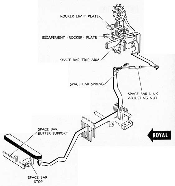
1. Movement of the Line Space Lever (to the right) causes movement of the Line Space Pawl to engage tooth of ratchet and continue the movement forward until Line space Pawl contacts Line Space Pawl Eccentric screw which completes the movement of the ratchet. The Line Space Detent Roll engages the tooth of the Ratchet and sufficient tension applied to the roll holds the ratchet in correct position.
2. ADJUSTMENTS:
a. Line Space Lever must be free from bind on its pivot and Line Space Lever Spring must provide sufficient tension to return Line Space Lever to normal position after operation. When the Line Space Lever contacts its Eccentric Stop Screw, Line Space Detent Roll should be securely engaged in ratchet tooth. If the Line Space Lever Eccentric Stop Screw is set so that Line Space Detent Roll is not seated securely in ratchet tooth the cylinder will creep forward (during writing) and eventually seat the ratchet tooth
properly, causing an uneven line. To adjust, loosen Line Space Lever Eccentric Stop Screw Nut and turn Eccentric Stop Screw until adjustment is made. Tighten Lock Nut. Line Space Lever Spring Tension may be increased or decreased by adjustment (see inset).
b. Line Space Pawl. Adjustment should be made so that when Line Space Lever contacts its Eccentric Stop Screw, there will be a little movement between the Line Space Pawl and the Line Space Pawl Eccentric Screw, which can be observed by holding Line Space Lever to its stop screw and turning the platen knob.
c. Detent Spring. Tension on Line Space Detent Roll may be increased or decreased by adjustment of Line Space De-tent Adjusting Screw. Turning Line Space Detent Adjusting Screw counter-clockwise will increase tension on De-tent Roll; turning clockwise will decrease tension on Detent Roll.
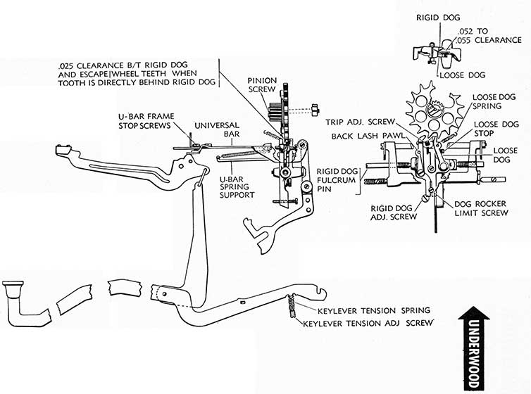
UNDERWOOD
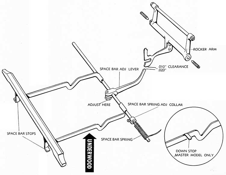
1. Movement of the Line Space Lever causes the Line Space Lever Tip to contact and move the Line Space Plunger to which the Line Space Pawl is attached. The Flat Line Space Pawl Spring rides on the flat protrusion of the Line Space Adjusting Lever which guides the position and action of the Line Space Pawl, according to the spacing set by the Line Space Adjusting Lever. When the Line Space Pawl clears the flat guiding protrusion of the Adjusting Lever, the Lane Space Pawl Spring (flat spring located on Plunger frame) forces the pawl downward to engage the Ratchet tooth. The R. H. Stop Stud Rubber limits tile throw of the Line Space Lever and the Line Space Pawl, thereby limiting the spacing of the platen throw to 1-2-or 3 spaces as set by the Line Space Adjusting Lever.
2. ADJUSTMENTS:
a. Line Space Lever. The Line Space Lever Tip should engage the Line Space Plunger lightly when in inactive position. In active position. Line Space Lever must turn platen Ratchet exactly 1, 2 or 3 spaces as determined by position of Line Space Adjusting Lever without underthrow or overthrow. Adjustment is made by loosening R. H. and L. H. Stop Stud Rubber Screws and Line Space Lever Screw Nut (all located under carriage frame beneath their respective members). All of these members are eccentric and pins are located in the top of carriage frame for location between the teeth of the eccentric stud rim. Adjustment may be made
after loosening screws by forcing Stud Screw upward, which will disengage Stud Rim Teeth from pin. Before tightening screws, be sure Stud Rim Teeth are positioned properly on their respective pins. Adjust position of Line Space Lever Tip in its relation (while in inactive position) to Line Space Plunger by adjusting L. H. Stop Stud Eccentric and Line Space Lever Eccentric. Adjust overthrow with R. H. Stop Stud Rubber Eccentric.
b. Line Space Pawl should clear Line Space Stop Pawl by .005 to .010" as shown in drawing, when Line Space Lever is contacting R. H. Stop Stud Rubber. Adjustment can be made by forming bottom of Line Space Pawl Stop. Be careful that top of Stop does not move when forming is done. Line Space Pawl must engage ratchet teeth properly when set for 1, 2 or 3 spacing.
c. Line Space Adjuster Lever should be free on its bearing with proper tension to hold Lever in position. Tension adjustment is made by forming flat tension spring.
d. Detent. Detent roller arm should be free on its bearing, and Detent Roll should roll freely on the arm and be in good condition. Detent Arm Spring should have sufficient tension to insure free and positive movement of the ratchet. Tension adjustment is made by forming end of Detent spring (upward to increase tension; downward to decrease tension).
53
54
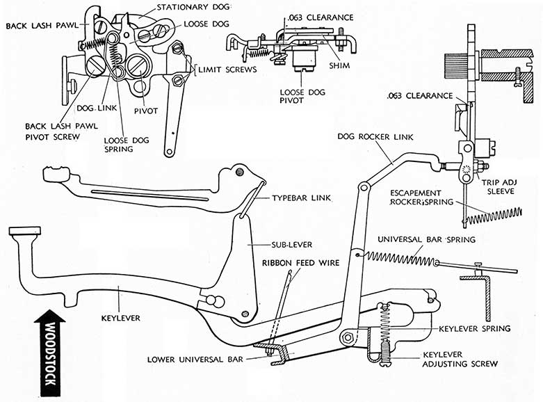
WOODSTOCK
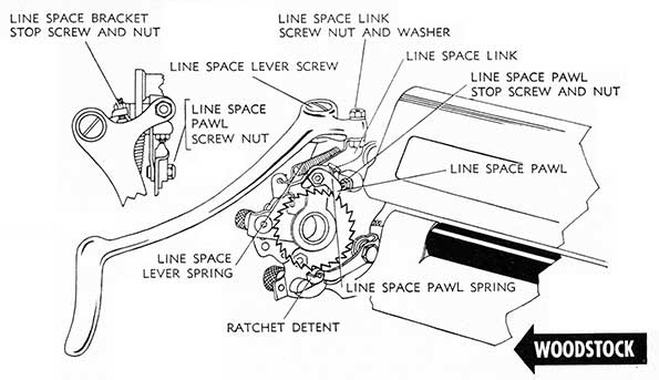
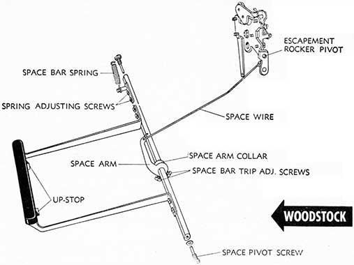
1. Line spacing is governed by the Line Space Link attached to the arm of the Line Space Lever, to which is attached the Line Space Pawl assembly. As the Line Space Lever is moved (to the right) the Line Space Pawl Spring forces the Line Space Pawl down to engage ratchet tooth immediately and continuing forward moves the ratchet and platen the number of spaces determined by the position of the Line Space Gauge. The throw of the Line Space Lever is determined by the position of the Line Space Gauge, moving the shortest distance when Gauge is set in Single Spacing or Top position. Line Space Lever and Line Space Pawl Stop Screws limit the movement of both parts and prevent overthrow or underthrow.
2. ADJUSTMENTS:
a. Line Space Lever must fit snugly on its bearing, the Line Space Lever Screw, without binding. Up and down play in the Lever should be removed by tightening Line Space Lever Screw and Nut, which should be tightened by holding the lever to extreme right while loosening nut and simultaneously tightening screw and locking nut. Lever should return to its normal position quickly and up and down play should be reduced to an absolute minimum. Line Space Lever, if bent down, may be straightened by holding Lever at point of Pivot screw while bending upward on end of lever.
b. Line Space Pawl. The correct throw of the Line Space Pawl is regulated by the Line Space Bracket Stop Screw and Nut and the Line Space Pawl Stop Screw and Nut. To adjust, loosen both lock nuts and move the Line space lever
to the right until the roller on the ratchet detent engages between the ratchet teeth at extreme end of the throw; then holding the Line Space Lever in this position, adjust the Line Space Bracket Stop Screw and Line Space Pawl Stop Screw until they both just touch their respective members. Tighten both lock nuts.
If movement of the Line Space Lever fails to space the platen, inspect the Line Space Pawl Spring for breakage. Spring may be replaced by loosening Line Space Pawl Screw Nut and moving space lever to the right so that the Line Space Pawl will move past its stop to the pawl. The old spring may now be removed and a new spring placed in position in the hold atop the pawl; guide the pawl back into position and tighten pawl nut. Pawl screw should be tightened and held in position by pawl nut.
c. Line Space Lever Spring. Broken Line Space Lever spring may best be replaced by loosening Line Space Link Screw Nut (located atop Line Space Lever arm) and pushing screw down (don,t lose washer under nut) to disengage from line space lever. Lever may then be swung around to the left to disengage old spring and replace with new one on spring arm bracket and Line Space Lever. Replace Line Space Link Screw into bearing position on Lever Arm; replace washer and tighten nut.
d. Detent. The Detent Roll should be positioned to engage teeth of the ratchet squarely, and Detent Spring should provide sufficient tension to set roll properly between teeth of ratchet. Detent Roll Spring may be formed to provide proper tension and Detent Roll Arm may be formed to locate in ratchet teeth squarely.
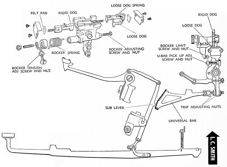
L. C. SMITH
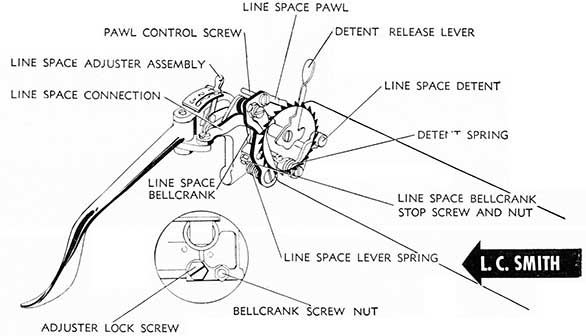
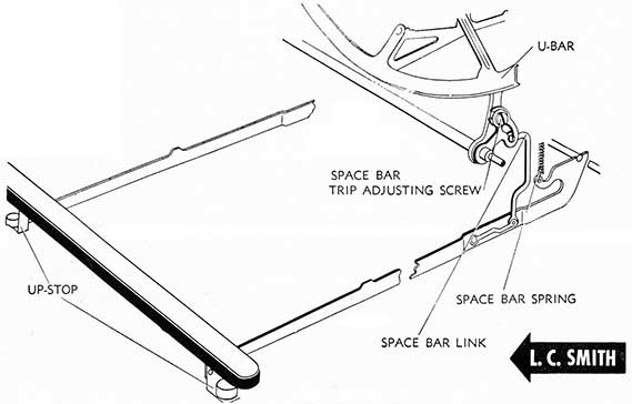
1. Movement of the Line Space Lever (to the right) causes the Line Space Connection to move the Line Space Pawl into engagement with Ratchet Teeth and to move the Ratchet (and the Platen) the number of spaces determined by the position of the Line Space Adjuster Lever. When the throw has been completed, the Detent Roll must rest between the teeth of the Ratchet with Line Space Lever limited by Line Space Bellcrank Stop Screw contact with the Platen Bushing. As the Line Space Assembly is attached to the Left Carriage End Plate, if the carriage end plate binding screws are loose, the Line Space Mechanism will be affected.
2. ADJUSTMENTS:
a. Line Space Lever must be free on its pivot and Line Space Lever Spring must provide sufficient tension to return Line Space Lever to inactive position after operation. Line Space Lever Pivot Screw and Nut control the Line Space
Lever and the Line Space Lever Spring may be formed to increase or decrease tension.
b. The Detent Roll must be positioned properly to rest between the teeth of the ratchet when the throw has been completed. Adjustment may be made by loosening the Adjuster Lock Screw and moving the Adjuster Assembly into proper position so that the Detent Roll will engage between the ratchet teeth.
c. The Line Space Bellcrank Stop Screw limits the throw of the Line Space Lever by contact with the Platen Shaft hub. It should be adjusted, after loosening lock nut, to stop movement of the Line Space Lever when the Detent Roll rests between the teeth of the ratchet at the completion of the throw.
d. Line Space Pawl. The back arm of the Line Space Pawl must rest on top of a tooth when the forward extension is engaged in the teeth of the ratchet (see Drawing), to prevent over-throwing. The Back Arm of the Pawl may be formed, if necessary, to provide proper fitting.
55
56
MARGIN STOPS AND LINE LOCK
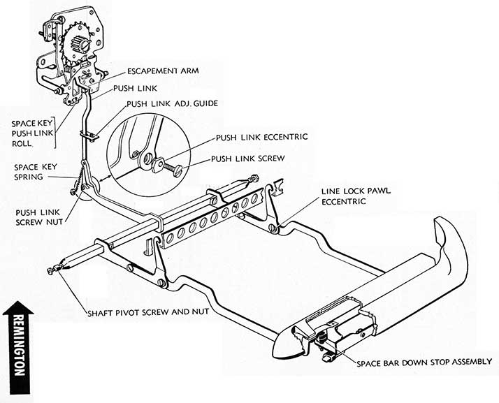
REMINGTON
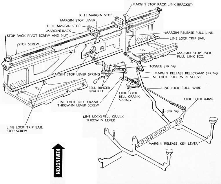
1. The Margin Stop on the right controls the left margin, while the Margin Stop on the left controls the right margin and line lock mechanism of the Remington #17.
The Line Lock-Bell Ringing Mechanism is moved into action when the L. H. Margin Stop contacts the Margin Stop Lever which in turn engages the Line Lock Trip Bail and moves it downward. When the L. H. Margin Stop first contacts the Margin Stop Lever (on the carriage) movement downward of the Line Lock Trip Bail contacting the Bell Ringer Bracket Arm Roller trips the bell. Five or six spaces after the bell rings on Pica machines, seven or eight spaces after the bell rings on Elite machines, the Line Lock Bell Crank Throw-in Lever Screw will contact the Line Lock Bellcrank Bracket which, through the Line Lock Pull Wire will position the Line Lock U-bar to lock the keylevers and space lever.
2. ADJUSTMENTS:
a. The Right Hand Margin Stop, controlling the left margin, should be so positioned that when in contact position with the Margin Stop Lever there is a clearance of not more than .060". If there is greater clearance over-throw trouble will result. If there is less clearance, Banking trouble will result. Adjustment is made after loosening Stop Rack Pivot Screw Lock Nuts by moving Margin Rack to the right or left, as may be necessary, hacking out one Stop Rack Pivot screw while coming in with the other. Tighten Lock Nuts when adjustment has been made. Margin Rack should be free on its pivots with a minimum of end play.
b. Line Lock:
(1) Margin Stop Lever, when held limiting on its bracket depressing the Line Lock Trip Bail, should cause the Line Lock Trip Bail to just clear its Line Lock Trip Bail Stop Screw. Check bail for trueness, form true if necessary, and position Line Lock Trip Bail Stop Screw.
(2) Margin Stop Rack must be free on its pivots
with minimum of end play and should be adjusted to provide one ring of the bell when Margin Stop contacts Margin Stop Lever. Adjustment is made after loosening lock nut (located behind and at top of Line Lock Bell Crank Throw-in Lever-See Drawing) and adjusting Line Lock Bell Crank Throw-in Lever Eccentric Screw (not marked on drawing) until it causes the Throw-in Lever to hold the Line Lock Trip Bail in its highest position. Tighten Lock Nut. Adjust Margin Stop Rack Pull Link Eccentric until bell rings one time on contact of Margin Stop with Margin Stop Lever.
(3) Line Lock U-Bar. The Line Lock U-Bar should be adjusted so that the U-Bar will lock keylevers 5 or 6 spaces after bell rings on Pica machines and 7 or 8 spaces after bell rings on Elite machines. Adjustment may be made with Line Lock Bell Crank Throw-in Lever Screw after loosening lock nut. Tighten lock nut after adjustment has been made.
The Line Lock U-Bar must be free on its pivots with a minimum of end shake. The Line Lock U-Bar lip in normal position (not operating) should clear depressed keylevers by 1/16". Adjustment may be made with Line Lock Pull Wire Sleeve after loosening Lock Nut. After Line Lock has been released, and Margin Stop moves to the left of Margin Stop Lever, return of carriage should not cause Margin Stop Lever to lock Line U-Bar in position or ring the bell. Adjustment may be made by stoning or emerying off any burrs on Margin Stop Lever Contact facing and buffing margin stop contact points.
(4) Springs. Margin Stop Lever, Bell Ringer, Line Lock Bell Crank and Margin Release Bell Crank Springs must be tensioned sufficiently to perform their f unctions.
(5) Margin Rack Stop Screw must be adjusted to limit Margin Rack when Margin Release Pull Link moves rack upward to disengage Margin Stop from Margin Stop Lever.
57
58
ROYAL
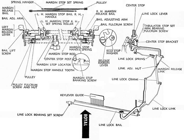
1. MAGIC MARGIN. The principle of Spring Action Margin Stops employed in the Magic Margin Model Royal, relies upon the tension of the Spring to move the Margin Stops (left and right) when pressure against the Margin Stop which is exerted by the Margin Bails (left and right) is released, permitting freedom of movement to the Margin Stop involved in the direction of the Spring Pull. Movement is permitted to the point where the carriage might be seated in its relation to the Frame Center Stop (the printing point as reflected by the type guide). The Left Margin Stop can move only to the right under spring tension power and the Right Margin Stop can move only to the left under spring tension power. Return power (to the left for the Left Margin Stop and to the right for the Right Margin Stop) is motivated manually after releasing the left or right Margin Release Bail by moving the carriage in the opposite direction.
One end of the Margin Stop Set Spring is attached by the Spring Hanger to the Left Margin Stop and the spring is threaded over the right pulley and back under and through the left pulley, the other end is attached to the Right Margin Stop with the Spring Hanger.
LINE LOCK. As the Right Margin Stop contacts the Line Lock Lever at the Center Stop position, the Line Lock Lever kick-out at its bottom extremity, pivots the Line Lock Link drawing the Line Lock Bail into position to lock the keylevers and Space levers.
2. ADJUSTMENTS:
a. Margin Stop Mechanism:
(1) Margin Stops must be free on Margin Stop Rod and the Margin Stop Set Spring Roller (right and left) must be free from bind on Margin Release Bail. Pulley Fulcrum brackets (left and right) located under Margin Stop Rod must be securely fastened to carriage ends and Pulley Fulcrum Screw and nut must not be tightened to cause a bind in pulley which must be free on its fulcrum.
(2) Margin Stop Banking Screws (left and right) provide proper adjustment in the event Margin Stop is banking or overthrowing. Before making this adjustment, check Escapement Pinion Pawl to determine if it drops into pinion tooth when Margin Stop contacts Margin Stop Locator. Move Left Margin Stop to the left and release, by moving Left Margin Release Lever forward, noting when Left Margin Stop contacts Left Margin Stop Locator, after first returning Left Margin Release Lever to its normal position, whether Margin Stop Handle Tooth seats itself in Margin Stop Rod Tooth. Check Margin Stop Locator Spring to determine if it has sufficient tension to return to normal position. Adjust Margin Stop Banking Screw (inset) to insure proper margin stop to eliminate banking or over-throwing. Margin Stop Banking Screws may be made accessible by moving carriage to the extreme right or left, whichever is necessary, disconnecting Bail Lift Screws, and swinging Margin Release Bails hack out of position.
(3) Margin Stop Set Spring may be replaced, when necessary, by first removing Margin Stop Set Spring Guard retaining screws. Disconnect spring from Left and Right Margin Stops. Thread end of new spring up through Left Pulley and attach end of spring to Right Margin Stop with its Spring Hanger. Thread other end of spring up through Right Pulley and attach to Left Margin Stop.
(4) Margin Release Bails (right and left) are pivoted on Right and Left Bail Fulcrum Screws which
are attached to the Keyset Tabulator Rack. If the Keyset Tabulator Rack is not square with the carriage it will cause the Margin Release Bail to bind against the Margin Stop Bail Handle (on the Margin Stop) which will affect movement of the Margin Stops. The Margin Stop Rod and the Margin Release Bails (left and right) must be absolutely parallel. There is no adjustment provided for adjusting spacing between the Margin Release Bails. Margin Release Bails should be free from bind on their pivots, tolerance being provided by Bail Fulcrum Screws. Bent or misformed Margin Release Bails will not operate efficiently and should be straightened or replaced.
(5) Bail Adjusting Arms (right and left) provide adjustment, by forming, to control the throw of the Margin Release Bails. These Arms should be adjusted so that when Margin Release Lever is in forward position (toward the operator) it will lift the Margin Stop Handle Tooth (via the Margin Stop Bail Handle) approximately 1/64" to 1/32" from the Margin Stop Rod, but the adjustment should not cause the Margin Release Bail to prevent free movement of the margin stop Bail Handle.
(6) Margin Release Lever Eccentric Stop Washer located directly behind the Margin Release Lever on each carriage end provides proper stop for the Release Lever. This eccentric stop washer should be adjusted so that Bail Lift Screw is centrally located on the notch in the Margin Release Lever. Margin Release Lever must not interfere with Paper Holder Arm when release lever is set in forward (toward the operator) position.
b. Line Lock Mechanism:
(1) Center Stop Adjustment. The Right Hand Margin Stop Banking Screw must make positive contact with the Center Stop and take purchase of not less than 3/32" on Margin Stop Banking Screw Head. This adjustment is made by shortening or lengthening Margin Release Link after disconnecting Link from Line Lock Release Lever. Shortening (turning loosened end of Margin Release Link into Link Adjusting nut, clockwise) will decrease, and lengthening (turning loosened end of Margin Release Link out of Link Adjusting nut, counter-clockwise) will increase the amount of purchase Margin Stop Banking Screws will take on Center Stop.
Loose side play should be eliminated in Center Stop by loosening Tabulator Stop Set Arm Bearing and turning in Fulcrum Screw until proper fit of Center Stop and Center Stop Bracket is secured.
(2) Margin Release Link. With adjustments made as outlined in Paragraph a above, Margin Release should operate correctly. If not, further adjustment can be made by turning, in or out, Margin Release Link.
(3) Line Lock Bail should be free on its bearings without excess end play. Adjustment is made with Line Lock Bearing after releasing set screw.
(4) Line Lock Link may be formed by shortening or lengthening to position set of Line Lock Bail. With Margin Stop Banking Screw contacting Line Lock Lever, Line Lock Bail should be resting lightly against Keylever Comb. Forming Line Lock Lever away from Center Stop at point just below its tip will lengthen throw of Line Lock Bail. The Line Lock Lever should fit squarely against Center Stop when contacted by Margin Stop Adjusting Screw.
59
60
UNDERWOOD
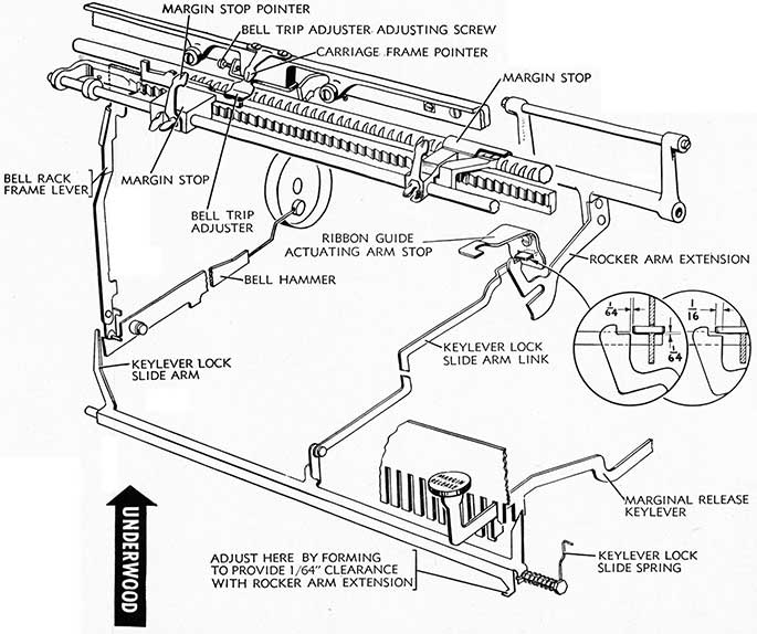
1. The Right Margin Stop controls the left margin while the Left Margin Stop controls the right margin and line lock on the Underwood Typewriter. It is important that Margin Stop Levers should seat on Margin Rack teeth properly and Margin Stop Release Levers should free stop. The Margin Stop Rod should be clean to provide easy movement of stops.
The margin stop on the left controls the Line Lock through action on the Bell Rack Frame, Bell Rack Frame Lever, Key-lever Lock Slide Arm and the Keylever Lock Slide Arm Link which moves into position to lock the Rocker Arm Extension, preventing the Escapement Rocker from operating when the Bell Trip Adjuster of the Carriage Skeleton moves into position on the margin stop.
2. ADJUSTMENTS:
a. Margin Stop. The Right Margin Stop Pointer should align with Carriage Frame Pointer when both are set in same position on scale. Adjustment is made by loosening Front Scale Screws and Margin Stop Handle knob and synchronizing these parts. Tighten screws and knob when adjustment has been made. Margin Stop Spring should provide sufficient tension to hold stop engaged. Spring may be replaced by dis-assembling Margin Stop after removing from Margin Stop Rod.
b. Banking Adjustment. The Right Margin Stop which controls the left margin, if overthrowing or banking. may be adjusted by adding or removing Front Margin Rod Washers. The Wheel Check (see Rack, Pinion and Starwheel) should be positioned properly, without binding, to check escapement wheel when adjusting.
c. Line Lock:
(1) The left Margin Stop, which controls the Right Margin and Line Lock mechanism is shaped to cause bell ringing and line locking when engaged by the Bell Trip Adjuster.
(2) The Bell Trip Adjuster should be adjusted so that Adjuster will move over margin stop without being retarded or slowed down and should engage margin stop 3/32". Adjustment is made by forming Bell Trip Adjuster.
The Bell Trip Adjuster should be adjusted so that
when carriage is at extreme left, escapement wheel tooth will be directly in front of the Escapement Rigid (Stationary) Dog. Adjustment is made by loosening Bell Trip Adjuster binding screws and adjusting Bell Trip Adjuster Adjusting Screw. Tighten binding screws when adjustment has been made.
When the Bell Trip Adjuster contacts the first step of the margin stop, the bell should ring. Adjustment is made by raising or lowering Bell Rack Frame. Bell Rack Frame Lever must be positioned to raise Bell Hammer and engage Keylever Lock Slide Arm when Bell Trip Adjuster contacts the first step in Margin Stop. Adjustment is made by loosening Bell Rack Frame Lever Screws and raising or lowering Bell Rack Frame Lever.
When the Bell Trip Adjuster contacts the second step of the Margin Stop, the keylevers must lock, which position is predetermined at 7 spaces after the bell rings. Adjustment is made by forming Keylever Lock Slide Arm.
With the keylevers locked as Bell Trip Adjuster contacts second step of the Margin Stop, by depressing Margin Release Key, carriage should move four spaces and relock. Adjustment is made by forming the right step of the Bell Trip Adjuster. After the second lock, by depressing Margin Release Key, provision is made for one more typed impression before Escapement Stationary Dog locks against starwheel tooth.
d. Keylever Lock Slide Arm Link clearance with Rocker Arm Extension, with keylevers locked, should be 1/16" (see inset in drawing). Adjustment is made by forming Key-lever lock slide arm. Keylever Lock Slide Arm Link clearance with Rocker Arm Extension, with Line Lock inoperative and keylever depressed, should be 1/64". Adjustment is made by forming Keylever Lock Slide Extension at point indicated in drawing.
Keylever Lock Slide and Lock Slide Arm Link should move freely on their pivots.
When keylevers are locked there should be a clearance between flat forming of Rocker Arm Extension and bottom of Lip of Keylever Lock Slide Arm of 1/64". Adjustment is made by loosening Ribbon Guide Actuating Arm Stop Screws and positioning Ribbon Guide Actuating Arm Stop.
61
Underwood margin stops and line lock
62
WOODSTOCK
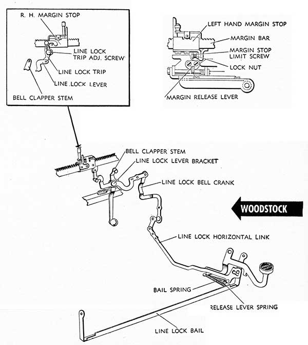
1. MARGIN STOPS. The Left Margin Stop controls the left margin by contact of the Margin Stop Limit Screw with the Margin Stop Lever. The Margin Stop Lever position in relation to the Margin Stop Limit Screw is governed by the position of the Margin Release Lever, which, if incorrectly seated on the Lever may dislocate the Lever from Limit Screw position. Raising the rack (by depressing the Carriage Release Lever) lifts the Margin Release Lever and as it is positioned on the Margin Stop Lever it forces the Margin Stop Lever to pivot back out of engagement with the Margin Stop permitting the carriage to move back beyond the Margin Stop Lever.
LINE LOCK. The Right Margin Stop controls the bell trip and Line Lock Bail through the action of the Line Lock Trip on the Bell Clapper Stem and Line Lock Lever. The Space Bar is not affected by line lock mechanism but the mechanism is so adjusted that the keylevers remain locked for four space bar trips before the keylevers are automatically unlocked. Woodstocks above 630,000 are not equipped with Line Lock Bail or Margin Release Keylever. In place of Line Lock mechanism, a double bell ringing is provided through a union o f the Line Lock Lever and Bell Clapper Stem.
2. ADJUSTMENTS:
a. Margin Stops:
(1) Roth Margin Stops must be free to slide along the Margin Stop Bar and the spring action of the Margin Stop Lock Lever must lock the stop in position when the handle is released.
(2) L. H. Margin Stop Limit Screw controls the left Margin when the L. H. Margin Stop contacts the Margin Stop Lever. If carriage is over-throwing, adjustment is made by loosening Margin Stop Limit Screw Lock Nut and turning Margin Stop Limit Screw. Turning Limit Screw counter-clockwise will correct overthrowing. Turning Limit Screw clockwise will correct banking. Adjust until correctly set, checking with front and margin scale to determine that they correspond, then tighten lock nut.
b. Line Lock Mechanism:
(1) The R. H. Margin Stop Line Lock Trip controls the bell trip and sets the Line Rock Bail when the Trip contacts the Line Lock Lever. The Line Lock Trip should be adjusted so that it contacts the Line Lock Lever and acts on the bail to lock keylevers at position selected. Adjustment is made by loosening Line Lock Trip Adjusting Screw and moving Line Lock Trip to proper position. Tighten Trip Adjusting Screw when adjustment has been made.
(2) The Line Lock Bell Crank pivots on shoulder screw on right rear post of machine frame and is held to shoulder screw by binding screw entering through Line Lock Bell Crank which is located behind Shift Keylever Extension. If binding screw becomes loosened, permitting Line Lock Bell Crank to disengage itself from shoulder of pivot screw, the line lock mechanism will be affected and cannot be properly adjusted until Line Lock Bell Crank is returned to its pivot position on the shoulder screw and binding screw tightened. Binding Screw may be made accessible by locking Right Hand Shift Lock and using a Dutch (offset) screw driver, after positioning Bell Crank on shoulder pivot.
(3) Bell Clapper Stem-Line Lock Lever, Flat Spring located on rear carriage rail to the right of the escapement wheel provides tension (provided both binding screws are tight) for Bell Clapper Stem and Line Lock Lever. If broken, loose, or improperly positioned, the lever and stem will not function properly.
(4) Line Lock Bail should be free on its pivots without excessive end shake and should be true in its entire length. Adjustment may be made by forming pivot ends and bail cross bar.
(5) Bail Spring and Release Lever Spring must he attached and provide sufficient tension to set and release Line Lock Bail.
(6) Margin Release Keylever must be free on its pivot and extension positioned properly under Line Lock Horizontal Link to raise Link when Margin Release Keylever is depressed (to unlock line lock). Adjustment is made by forming extension.
63
64
L. C. SMITH
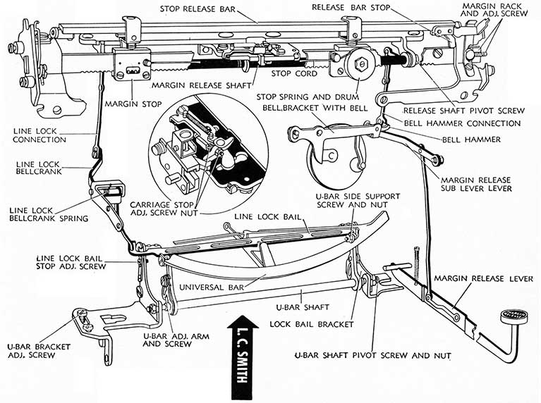
1. The Principle of Spring Action Margin Stops employed in the late model L. C. Smith relies upon the tension of the Stop Spring in the Stop Spring Drum to provide tension for moving the Left Hand Margin Stop to the right and the Right Hand Margin Stop, upon which the Stop Spring Drum is mounted, to the left, by the action of the Stop Cord joining the two. The Left Hand Margin Stop controls the Left Margin and the Right Hand Margin Stop controls the Right Margin and Line Lock. Movement of the Stops is controlled by one lever located on the right edge of the paper table. Moving the lever up to top position moves the Stop Release bar rear blade downward where it contacts the release arm on the Left Hand Margin Stop, and releases the Left Hand Margin Stop for free movement toward the Right Hand Margin Stop. Moving the lever down to bottom position moves the Stop Release Bar Front Blade downward, where it contacts the release mechanism of the Right Hand Margin Stop, freeing the R. H. Margin Stop for movement toward the Left Hand Margin Stop. Return of either stop, in the opposite direction, is performed manually after placing the Control Lever in the desired position. Moving the carriage to the right will move the Left Hand Margin Stop to the left; while moving the carriage to the left with Control Lever in down position will move the Right Hand Margin Stop to the right. When the Control Lever is in center (Neutral) position, both Stops are locked in position.
As the Right Hand Margin contacts the Carriage Stop (inset), the form of the Stop Arm on the Margin Stops forces the Carriage Stop to the rear, which, in turn, turns the Margin Release Shaft and throws the Line Lock Connection downward, where the Line Lock Bellcrank moves f or-ward, allowing the Line Lock Bail to drop into position behind the Universal Bar, preventing further escapement action of the Escapement Rocker.
When the Right Hand Margin Stop first contacts the Carriage Stop, slight movement of the Margin Release Shaft causes the Bell Hammer Connection to trip the Bell Hammer. Eight spaces later the line lock mechanism locks the Universal Bar.
2. ADJUSTMENTS:
a. Margin Stop Mechanism:
(1) Margin Stops must be free on the Margin Stop Rod and the Margin Stop Release Coil Spring must provide sufficient tension to return setting arm of Margin Stop to inactive position when the Stop Release Bar releases the Stop Release Plunger. Margin Stop Assembly Screws should be tight.
Right Hand Margin Stop Spring Drum must work free on its pivot and provide sufficient tension to move the stops. Tension may be increased by winding drum with the fingers, positioning the stop cord properly when proper tension has been secured. Proper tension should be six turns of the drum.
To Replace Margin Stop Spring, remove Tension Screw Lock Nut and remove drum cover. New spring
may be installed, and tension applied as outlined above. Replace Drum Cover and lock nut.
To Replace Stop Cord, remove Stop Spring, as outlined above. Feed new stop cord from inside of drum out through slot, tying knot in end to remain inside of drum. Replace Spring, Drum Cover and Lock Nut. A slip knot in opposite end of stop cord fits over stud in Left Margin Stop.
(2) Margin Stop Banking Adjustments:
Right Hand Margin Rack Adjusting screw provides for movement of the Margin Rack to the left or right to overcome banking or over-throw, after loosening left and right hand margin rack binding screws. Slots in Margin Rack are provided for this adjustment. Tighten binding screws when adjustment has been made.
(3) Stop Release Bar operated by the Margin Stop Release Lever operates within the confines of the upper and lower limit plates attached to the Lever. Limit plates must be adjusted (by forming) to provide just sufficient upward and downward movement of the Stop Release Bar to free the Margin Stops, without binding them.
Stop Release Bar Spring may be formed to provide sufficient tension to retain Stop Release Lever in central (neutral) position. Stop Release Bar must be pivoted in Release Bar Bracket snugly fitted. Adjustment may be made by forming Bracket Arms.
b. Carriage Stop (See Inset) is adjusted for the operation of the Right Hand margin stop only. The Carriage Stop should be adjusted by its Adjusting Screw so that it moves freely to the notched Margin Stop Stop-Arm where the line lock should be set, and when the Margin Release Lever is depressed, the Carriage Stop should move out of engagement with the Stop Arm, permitting the Margin stop to pass the Carriage stop, the Carriage stop returning to engaging position after being passed.
c. Line Lock and Release Mechanism. Determine that all parts are free on their pivots without bind or excessive end shake. Determine that Space Bar is not holding Universal Bar partly engaged before attempting Line Lock adjustments.
(1) Line Lock Bellcrank must be formed so that the Line Lock is not released until the Carriage Stop contacts the straight limiting surface of the Margin Stop Stop-Arm.
(2) Line Lock Bail should work freely on its pivots and should clear the Universal Bar Stops by .015" when margin release key is depressed. Adjustment may be made after loosening Line Lock Bail Bracket binding screw and positioning Line Lock Bail Bracket properly. Tighten Bracket binding screw when adjustment has been made.
(3) Line Lock Bail Stop Adjusting Screw may be adjusted to limit upward throw of the Line Lock Bail to clear the Universal Bar by .015" when Universal Bar is pushed back with type-bar contacting platen.
(4) Bell Hammer Connection must clear Bell Hammer. Adjustment may be made by moving Bell Hanger Bracket, after loosening Binding Screws.
65
66
RACK, PINION AND STARWHEEL
REMINGTON
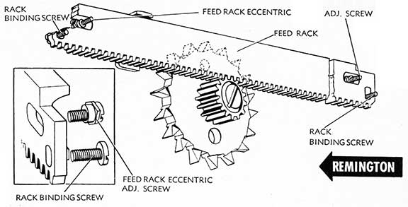
1. Both Pica and Elite pinion wheels in the Remington #17 contain 15 teeth, while the Elite Starwheel has 18 teeth and the Pica Starwheel has 15 teeth. The rack is permanently engaged in the Pinion and as the Pica and Elite pinions have an equal number of teeth (15), the same rack is used for both pitch machines. When the carriage release key is depressed, the Carriage Release Blade acts on the Escapement Loose Dog Release to release the Loose Dog from engagement with the Starwheel Tooth, permitting free movement of the carriage.
2. ADJUSTMENTS:
a. Rack. The Rack teeth must mesh properly in the Pinion Wheel Teeth without bottoming. Adjustment is made with the Rack Adjusting Screws and Feed Rack eccentric after loosening Rack Binding Screws. Elongated slots for both screws are provided in the Feed Rack, and the Rack should be adjusted uniformly on both ends.
To Remove Rack, remove Rack Binding and Adjusting Screws. Remove the Rack, which may be removed at either end of carriage.
b. Starwheel and Pinion are unified and for purposes of Backspacing the Loose Dog is disengaged from the Starwheel Tooth permitting both the Starwheel and Pinion to back up. Starwheel-Pinion combination should be free on its pivot.
To Remove Starwheel and Pinion, with unit out of machine, loosen Starwheel Shaft Lock Nut (from rear side of Unit). Turn out Shaft Screw (from front side of Unit). Starwheel and Pinion may be removed from Shaft.
ROYAL
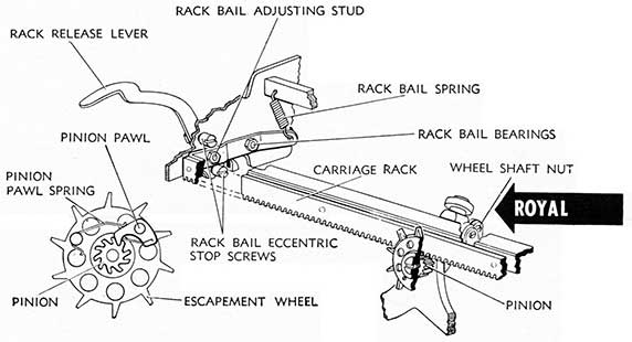
1. The Royal Rack is positioned on the Rack Bail by binding screws. Meshing of the Rack in the pinion is controlled by Lower Rack Bail Eccentric Stop Screws (on either end of carriage). The Rack Bail Spring provides the tension to retain the rack enmeshed with the Pinion.
The Starwheel and Pinion seat on the Escapement Frame of the Lower Carriage Rail Assembly and may be made accessible for adjusting by removal of the Carriage (see Main Carriage) or by removal of the Lower Carriage Rail (see Motion and Shift Mechanism).
2. ADJUSTMENTS:
a. Rack:
(1) Rack Teeth should mesh as deeply as possible in the Pinion Wheel without binding. Adjustment may be made with the Lower Rack Bail Eccentric Stop Screws, after loosening lock nuts. Adjustment must be uniform on both ends of the Rack Bail.
(2) Rack Bail Arms should be parallel and Rack Bail should be true in its entire length. Rack Bail Arms may be formed if necessary to parallel.
(3) Rack Release Lever should be free on its pivot with slight play (not limiting the Rack).
(4) Rack Bail Eccentric Stop Screws (upper), right and left, limit upper movement of Rack when Rack Release Lever is depressed and should be adjusted so that with Rack Release Lever depressed, Rack will clear pinion teeth by 1/16".
(5) Rack Bail Adjusting Stud provides adjustment to remove end shake in Rack Bail. End shake in Rack may cause crowding or piling and should be reduced to an absolute minimum with bail pivoting freely.
(6) To Remove and Replace Rack, back out Rack Binding Screws binding rack to rack bail. Rack may be removed from either end of carriage. When installing a new rack care should be taken that an Elite Rack replaces an Elite Rack, etc.
b. Starwheel must be free on its shaft and shaft nut should be adjusted, after loosening set screw, to provide a little play between pinion wheel and Escapement Frame.
Starwheel Shaft must be true and Starwheel must be plumb. Bent or deformed starwheel teeth or bent Shaft will cause escapement to skip or pile.
To Remove Starwheel and Pinion Shaft Mechanism, loosen Escapement Wheel Shaft Nut set screw and remove Escapement Wheel Shaft nut. Remove Shaft assembly from front of Escapement Frame.
c. Pinion must be free on its shaft. Pinion Pawl must be free on its pivot and pinion pawl spring tensioned properly to hold pawl in pinion teeth. Note position of pinion teeth in relation to pinion pawl. In replacing pinion care should be taken that Elite pinion is installed in Elite machine and Pica pinion in Pica machine and that teeth face in proper direction (see drawing) otherwise improper meshing of the pinion by the pawl will result in skipping.
67
68
UNDERWOOD
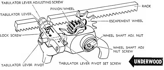
1. The Underwood Rack is positioned on Rack Arms by two pins through each arm end and through the Rack. The Rack Arms pivot on either end of the Main Carriage Casting. Meshing of the Rack Teeth in the Pinion Wheel is controlled by the Tabulator Lever Adjusting Screw, with which the Rack may be raised or lowered through the action of the Tabulator Lever Roller.
The Escapement Wheel of the Underwood runs on ball bearings and to the Escapement Wheel is fitted the Pinion Pawl and Pinion Pawl Spring, while the Escapement Wheel Pinion is located on the Wheel Shaft, and its position engaging the Escapement Wheel is controlled by the Wheel Shaft Adjusting Nut, which holds the two together as well as secures the Shaft to its bracket.
2. ADJUSTMENTS:
a. Rack:
(1) Rack teeth should mesh as deeply as possible in the Pinion Wheel without binding. Adjustment is made with the Tabulator Lever Adjusting Screw, after loosening Lock Screw.
(2) Rack Arms should be free on their pivots, and Rack End-play Adjusting Screw on Left Rack Arm should be adjusted to provide free action of the Arm without binding, but excess end shake should be eliminated.
(3) To Remove and Replace Rack, tap out two pins in each Rack Arm End. Remove Rack from Rack Arms. In replacing, be sure that new Rack has proper
pitch-teeth positioned identically. Pica racks contain 10 teeth to the inch and Elite racks contain 12 teeth to the inch. To replace rack, position ends properly in Rack Arms and replace two pins in each Rack Arm End, tapping them into position.
b. Starwheel and Pinion:
(1) Escapement (Star) Wheel should be free on its bearing and must be perfectly true vertically. Wheel Shaft must be true. The Escapement Wheel should fit snugly without binding. Adjustment may be made with Wheel Shaft Adjusting Nut after loosening Adjusting Nut Screw. Escapement Wheel teeth, if worn, will cause skipping.
(2) The Pinion Wheel is held in position on Star-wheel Shaft by Pinion Screw. The Pinion Pawl (seated on Escapement Wheel and held in position by Pinion Pawl Spring) forces the Pinion and the Rack to move with the Escapement Wheel when the carriage is moving to the left. When carriage is returned to the right, Pinion Pawl releases from the Pinion Wheel, permitting the Pinion Wheel to move with the rack and carriage while the Escapement Wheel is held in position by the Loose Dog.
(3) To Remove Escapement Wheel and Pinion, remove Carriage, Tabulator Housing and rear cover plates. Loosen Wheel Shaft Adjusting Nut Screw and remove Wheel Shaft Adjusting Nut. Wheel Shaft Cone and ball bearings may now be removed. Remove Starwheel and Pinion. Remove Pinion from Starwheel by removing Pinion Screw. To replace, reverse this operation.
WOODSTOCK
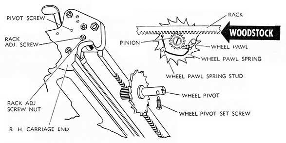
1. The Carriage Rack teeth, meshing properly in the Pinion Wheel, which, in turn, is held in its position by the Wheel Pawl, hold the carriage in position. When the Loose Dog moves out of position of the Starwheel tooth, the escapement action is permitted; the starwheel and pinion rotating as one the one-space allowed by the Escapement Rocker Dogs. When the carriage is moved to the right (either by the line space lever or by the Back Spacer) the Pinion Wheel Pawl permits the pinion to back up with the rack (the starwheel meanwhile being held in position by the escapement dogs or the Back Space Pawl) and when that backward (to the right) movement of the carriage has been completed, the Wheel Pawl drops into position in the Pinion Wheel tooth, locking the Pinion to the action of the Star-wheel in its movement with the carriage to the left.
2. ADJUSTMENTS:
a. Rack. The Rack teeth must be positioned properly in the Pinion Wheel Teeth, without bottoming. Adjustment is made with the Rack Adjusting Screw eccentric (one on each end of carriage) to raise or lower the rack into the pinion wheel teeth. Both adjustments should be uniform. After adjusting, check rack by depressing at each end to see if there is any play between the rack frame and the rack adjusting screw eccentric at point of contact.
The Rack Release Lever should be free on its pivots to provide free operation of the rack. Rack up-stop screw and lock nut are located in left end of Tabulator Stop Bar. Adjustment should be made so that rack, in raising, will not bind on wheel pawl spring stud in the event wheel pawl spring stud is momentarily positioned at top of starwheel.
b. Starwheel. The Starwheel (Escapement Wheel) should be free on its bearing and must be perfectly true vertically.
Wheel pivot, if bent, will prevent starwheel from retaining position in relation to Escapement Loose Dog. Pivot should be replaced, if bent. Soft or worn starwheel teeth will cause skipping.
The Starwheel Pivot is held in proper position on late model machines by Wheel Pivot Set Screw, located under rear top plate of the machine. Wheel pivot is recessed for proper positioning of wheel pivot set screw.
c. Pinion. The Pinion is held in position on the Starwheel with the Wheel Pivot Screw entering threaded end of the Wheel Pivot. Both the Elite and Pica Pinion Wheels and the Starwheel are composed of 16 teeth. The Pica Pinion is larger in diameter than the Elite Pinion. Care should be exercised in replacing pinion wheel to insure that teeth are pointing to the right (see drawing), otherwise skipping and improper carriage action will result.
d. To Remove Starwheel and Pinion. Remove Main Carriage (see Main Carriage). Remove Rear Carriage Rail. Do not alter rear carriage rail adjusting screws. The Margin Stop Lever Assembly, which is hinged to the left of Starwheel, may be moved out (toward you) of the key of the Back Space Plate and swung over (to the left), making the pinion and starwheel accessible.
Back out the Wheel Pivot Screw. The Pinion may now be removed.
Back out the Pivot Set Screw. Move the Starwheel and pivot in (toward you) until the pivot is free. It may then be removed. The Starwheel bears on the pivot and is held in place by the Pinion Wheel. It may be disassembled from the Pivot by applying slight pressure.
e. To Remove Rack. Remove sub-carriage (see Sub-Carriage). Remove Margin Bar Binding Screws two (2) at right outside end of carriage casting and one at left outside end of carriage casting opposite Margin Bar. Back out Rack Pivot Screws at either inside end of carriage casting. Remove Tabulator Bar (see paragraph b above). Disengage Rack Springs at either end of carriage. The Rack may now be removed.
69
70
L. C. SMITH
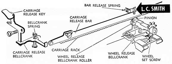
1. The Rack on the L. C. Smith Typewriter is permanently attached to the carriage casting (does not lift out of engagement with the Pinion) and is permanently engaged in the Escapement Wheel Pinion. When the Carriage Release Key is depressed, the Carriage Release Bellcrank contacts the roller on the Carriage Release Bar, moving the bar downward to engage the Wheel Release Bellcrank Roller which, in turn, through the Wheel Release Bellcrank depresses the Escapement Loose Dog, and disengages it from contact with the Escapement Wheel Tooth, permitting free movement of the carriage. The Bar Release Spring returns the Carriage Release Bar to inactive position when the Carriage Release Key is released. The Bellcrank Spring returns the Carriage Release Key to inactive position when the Release Key is released.
2. ADJUSTMENTS:
a. Rack:
(1) Carriage Rack Teeth must mesh securely in the pinion wheel without bottoming. Position of Carriage Rack is not adjustable. In installing a new Rack in machine, top edge of rack may be filed off to provide clearance with carriage casting. New Racks generally fit perfectly. The Elite (12 Pitch) Rack requires an Elite (15 tooth) pinion and Elite (15 tooth) starwheel. The Pica (10 pitch) Rack requires a Pica (12 tooth) pinion and Pica (12 tooth) starwheel.
(2) To Remove Carriage Rack, remove Carriage Release Bar Screws (one in either end of carriage casting) being careful not to lose washers resting on Carriage Release Bar Screws between the Rack and the Release Bar. Remove Carriage Release Bar, after disconnecting Release Bar Spring. Remove Carriage Rack Binding Screws (one in either end binding rack to carriage casting). Remove carriage rack.
b. Carriage Release Bar.
(1) The Carriage Release bar is separated from the Carriage Casting (over the top of the Carriage Rack) by Washers. It pivots on either end of the carriage frame on its own Carriage Release Bar Screws, which are seated in the V shaped slots of the Release Bar to guide it downward when the left or right Carriage Release Key is depressed. Rollers of the release bar, which are contacted by the Carriage Release Bellcrank (when the Carriage Release Key is depressed) should be free and the Release Bar Spring should have sufficient tension to return Carriage Release Bar to inactive position when Carriage Release Key is released. Carriage Release
Bellcrank should clear Carriage Release Bar roller by 1/8" in inactive position. Adjust by forming Contact Arm of the Carriage Release Bellcrank.
(2) To Remove Carriage Release Bar, remove Carriage Release Bar Screws (one at each end of Release Bar) and disconnect Carriage Release Bar Spring. Carriage Release Bar may be removed from either end of the carriage. To replace, reverse above procedure.
c. Wheel Release Bellcrank:
(1) Wheel Release Bellcrank Roller must be positioned to ride flush on Carriage Release Bar (when depressed). Adjustment may be made by forming Wheel Release Bellcrank Roller Arm to position roller properly.
(2) Wheel Release Bellcrank must be positioned properly in its relation to the Escapement Loose Dog, so that when the Carriage Release Bar contacts the Wheel Release Bellcrank Roller, the Wheel Release Bellcrank will contact and move the Loose Dog out of engagement with the Escapement Wheel tooth. Adjustment may be made by forming Wheel Release Bellcrank.
d. Starwheel and Pinion:
(1) The Starwheel and the Pinion in a machine must have an equal number of teeth and the Rack must correspond. Pica (10 pitch) should have 12 teeth in both Starwheel and Pinion. Elite (12 pitch) should have 15 teeth in each. Escapement wheel must be fitted snugly on its shaft and end shake reduced to an absolute minimum. Adjustment may be made, after loosening Wheel Set Screw, by positioning wheel properly. Tighten set screws when adjustment has been made. Grind in Pinion (when carriage is returned) may be eliminated by placing a drop of oil on Pinion Shaft.
(2) To remove Starwheel and Pinion disconnect Back Spacer Link (see Back Spacer), disconnect Ribbon Pull Link from Pull Arm (see Ribbon Cover), remove Escapement Connection Arm Pivot Screw on Universal Bar (see Universal Bar). Release Main Spring Tension by loosening ratchet nut and move Adjusting Pallet until tension is fully released. Release Spring Drum Bracket Top Plate binding screws (see Mainspring and Draw-band) alternately until Spring Drum Bracket is loose and can be removed. The Escapement Assembly is located on the Spring Drum Bracket, and removal of the Spring Drum Bracket removes the complete assembly. Starwheel and Pinion may be removed by loosening Wheel Set Screw and removing Starwheel from the rear, and Pinion and shaft from the front of the casting.
71
72
UNIVERSAL BAR
REMINGTON
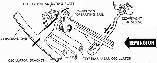
1. The Typebar Universal Bar operates in conjunction with the Typebar Universal Bar Oscillator and the Escapement Operating Bail in causing the Escapement Trip. The Universal Bar blade fits into the rear segment opening and the Bar pivots on the Typebar U-Bar Oscillator. As the Universal Bar is moved back (toward the rear of machine) by the cam shaped form of the typebar heel as it nears the printing point, the arm of the Universal Bar contacts the Escapement Operating Bail Roller. Continued movement toward back of the machine by the Universal Bar causes the top part of the Operating Bail to move toward the rear of machine while the bottom extension (note direction marks on drawing) moves forward (toward the front of machine). In this action the Escapement Link Sleeve pulls the lower extension of the Escapement Rocker forward, disengages the loose dog from the star wheel tooth and causes the escapement action.
2. ADJUSTMENTS. Before attempting adjustments check Universal Bar Oscillator Bracket Screws and the Oscillator Adjusting Plate Screws on each end of U-Bar Oscillator for tightness. Oscillator Pivot Screws should be adjusted for free action of the Oscillator with a minimum of end shake. Universal Bar Oscillator Spring should be checked to determine if it provides sufficient tension to retain the Universal Bar Blade in its forward position in the segment opening when in inactive position.
a. Universal Bar Oscillator should be free on its pivot and escapement arm connection to Escapement Link Sleeve should be positioned properly to prevent binding of Escapement Link
Sleeve in Rocker or Arm to Operating Bail.
b. Universal Bar Guide Stud must be located centrally and free in the segment guide hole. Adjustment may be made by positioning U-Bar Oscillator Pivot Screws, coming in on one and going out on the other until U-Bar is properly centered.
c. U-Bar Trip Position Adjustments. Before attempting adjustments because of lack of uniform trip on either end or center type bars, determine by raising Typebars #1, #21, and #42 to the platen whether trip is off in center of the Universal Bar or at left or right end of the U-Bar. If the Trip is off on the center bar, the Universal Bar Oscillator Bracket may be adjusted up or down after loosening Bracket set screws, which are located in elongated slots for adjusting purposes, by positioning Bracket correctly. Moving the Bracket up will cause the Escapement Trip on the center bars to take place when the typebar is closer to the platen. Moving the Bracket down will cause the escapement trip on the center bars to take place when the type bar is farther away from the platen. Tighten binding screws when adjustment has been made. Adjustment of Bracket up or down will affect trip on end bars. Adjustment should be limited to a very slight up or down movement of Bracket.
If the Trip is off at either end typebar, adjustment may be made after loosening Oscillator Adjusting Plate Screws on side involved. Moving adjusting plate to the rear will cause escapement to trip when typebar is closer to the platen. Moving Adjusting Plate to the front will cause escapement to trip when typebar is farther away from platen. Tighten Adjusting Plate Screws when adjustment has been made.
ROYAL
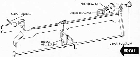
1. The Royal Universal Bar, operated exclusively by the Universal Bar Links, which pull the Universal Bar forward as the keylever is depressed, performs the function of tripping the escapement rocker and positioning the ribbon. The U-Bar does not utilize springs for return of the bar to inactive position. As will be noted by reference to Escapement Action drawings, the Universal Bar Links hook over the U-Bar Rod. Depression of a keylever moves the link forward drawing with it the U-Bar and causes the U-Bar Trip Plate to contact the Escapement Rocker Extension to cause the escapement.
2. ADJUSTMENTS:
a. Universal Bar must be free on its pivots. End shake adjustment is provided with adjustable slots in the R. H. U-Bar bracket. Determine that the U-Bar fulcrum is not
binding on the U-Bar hanger.
b. Universal Bar Ribbon Adjusting Screw controls Ribbon position. See instructions under Ribbon Cover.
c. To Remove U-Bar. Remove Fulcrum nut. Remove Bar fulcrum. Remove Universal Bar Link Spring Bracket Screws (bracket fitting Universal Bar Link Springs located directly below Universal Bar) and move Spring Bracket forward. Disengage Universal Bar Links from U-Bar Rod. U-Bar may now be dropped down and removed.
d. To Replace U-Bar. Position Universal Bar Links on U-Bar Rod. Return U-Bar to U-Bar Bracket and U-Bar Fulcrum to position. Replace Fulcrum Nut on U-Bar Fulcrum and tighten, providing minimum of end shake in U-Bar without binding. Replace Universal Bar Link Spring Bracket and Bracket Binding Screws. Check Link Springs for proper fitting on spring bracket.
UNDERWOOD
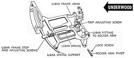
1. The blade of the Universal Bar fits into the opening in the back of the Typebar Segment in position to be contacted by the cam shape of the type bar heel, while the U-Bar Frame Arms are fitted to the Rocker Arm as shown in drawing. The U-Bar Frame Stop limits amount of purchase the U-Bar Frame blade can take in the Segment opening. As the type bar heel moves the Universal Bar back, the U-Bar contacts the Trip Adjusting Screw of the Escapement Rocker, causing the upper part of the Rocker to move back, disengaging the loose dog from the escapement wheel tooth, causing the escapement trip.
2. ADJUSTMENTS. Before attempting adjustments, remove Escapement Rocker and disconnect Loose Dog and U-Bar springs.
a. U-Bar Frame Arm must be free in its fitting to Rocker
Arm. Adjustment is made by forming U-Bar Frame Arm.
b. U-Bar Spring must provide just enough tension to return U-Bar to segment position. Adjustment is made by loosening U-Bar Spring Support Set Screw and positioning Spring Support. Tighten set screw when adjustment has been made.
c. U-Bar Guide Stud must be centrally located and free in the Segment Guide Slot. Facing machine from rear with cover plates removed, the Rocker Arm Pivot to the right is an eccentric adjustment for properly positioning the U-Bar blade and U-Bar Guide Stud. Adjustment is made by loosening Set Screws and moving Rocker Arm with the eccentric until proper fitting of both the Blade and Stud is
(Continued on page 74)
73
74
WOODSTOCK
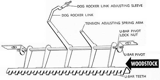
1. Woodstock Typewriters bearing serial numbers above 580,000 utilize the lower U-Bar teeth only for individual escapement trip.
Woodstock Typewriters bearing serial numbers below 580,000 are equipped with an Upper Universal Bar which motivates the escapement, which is pushed into contact position with the escapement trip screw by the cam type shape of the typebar heel. Such machines utilize the teeth of the lower U-Bar exclusively for the purpose of providing ribbon lift adjustment.
2. ADJUSTMENTS: Determine that U-Bar is parallel with bottoms of Keylevers and is not sprung out of shape before attempting adjustments.
a. Position. There should be practically no end play of the lower Universal Bar on its pivots, yet it must be perfectly free. U-Bar pivot lock nuts should be tight. Dog Rocker Link should not bind on its pivot, and it should be free in its positioning hole in the escapement rocker.
b. Tension Adjusting Spring should be attached to Spring
Arm and the Adjusting Plate seated in 1st, 2nd or 3rd position on adjusting plate post in rear frame cross bar. The central position is standard touch adjustment.
c. To Remove U-Bar, loosen Universal Bar Pivot Lock Nuts (right and left) backing out U-Bar pivots sufficiently to release the Universal Bar. Back out Dog Rocker Link Adjusting Sleeve lock nut and Dog Rocker Link Adjusting Sleeve. Disconnect tension adjusting spring plate. Remove Ribbon Feed Wire Nuts. The Universal Bar may now be withdrawn from the machine; do not bend the Dog Rocker Link.
d. To Replace U-Bar. Feed the Dog Rocker Link into position to reenter the Dog Rocker as you move the U-Bar hack into position. Tighten U-Bar pivot screws, keep U-Bar centered properly to prevent binding of the Dog-Rocker Link on Dog Rocker and at the same time contact keylevers properly with U-Bar teeth. Replace Dog Rocker Link Adjusting Sleeve and its lock nut. Connect Tension Adjusting Spring Plate. Tighten U-Bar pivot screw lock nuts. Test U-Bar for bind.
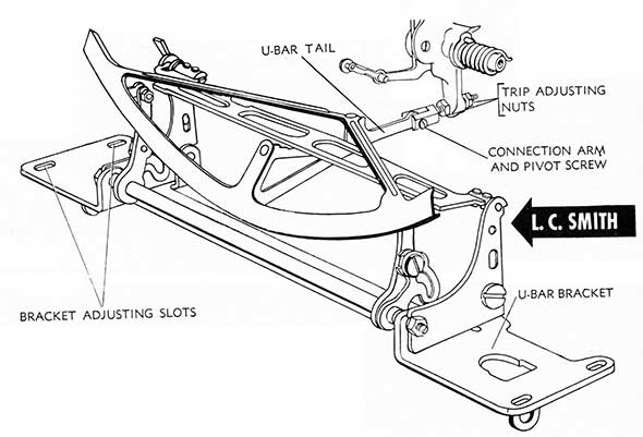
L. C. SMITH
1. The Universal Bar is connected directly to the Escapement Rocker and is motivated into position by the action of the sub-levers when a keylever is depressed. The Line Lock Universal Bar operates on the U-Bar Bracket also and when the Line Lock is set the Line Lock Universal Bar moves into position to block the movement of the U-Bar, preventing the Escapement Rocker from functioning. Spring tension for returning the U-Bar to inactive position is supplied by the Escapement Rocker Spring.
2. ADJUSTMENTS:
a. Position. The Universal Bar must be positioned parallel to the row of sub-levers, in order to provide a uniform Escapement Trip on all keylevers. Adjustment may be made after loosening U-Bar Bracket Binding Screws by adjusting U-Bar position so that trip is uniform on all Typebars. Tighten Binding Screws when adjustment has been made.
b. Individual Trip:
(1) Where individual Trip on a Single Typebar is not uniform with the balance of the typebars, trip on that typebar may be adjusted by peening or filing, whichever is necessary, the contact point on that sub-lever.
(2) Where trip on center type bars is not uniform with the trip of the end typebars, adjustment may be made by forming the tail end of U-Bar (up or clown) at point just forward of the connection arm connecting U-Bar to Escapement Rocker. Forming Tail downward (with three prong pliers) will cause center type bars to trip farther away from platen. Forming Tail upward (with three prong pliers) will cause center type bars to trip closer to platen. Extreme caution should be utilized in forming to limit bend to a minimum.
c. U-Bar Tail must fit loosely in Dog Rocker Connection Arm. Use a Hex wrench to position Connection Arm properly.
d. Universal Bar must operate free on its pivots with a minimum of end shake. Adjustment may be made with pivot screw after loosening lock nut.
e. To Remove U-Bar. Disconnect U-Bar from Escapement Rocker by removing connecting arm Pivot screw. Remove U-Bar Bracket Screws (4). Disconnect Line Lock Link. U-Bar may now be removed from machine. To replace, reverse above procedure.
UNDERWOOD (Continued from page 72)
made. Tighten Set Screws. Check Rocker Arm for free movement, end shake must be reduced to a minimum.
d. U-Bar Trip Position Adjustments:
(1) Before attempting adjustments because of lack of uniform trip on a typebar, determine by raising Type Bars #1, #21, and #42 to the platen by the fingers, whether trip is off in center of the Universal Bar, to the right or to the left. Check position of U-Bar as outlined in Paragraph c above, adjusting, if necessary. When adjustment has been made, check position of U-Bar Blade in its relation to both typebar #1 and #42 to determine if trip is uniform.
(2) After adjusting, the U-Bar must be free in its movement.
e. U-Bar Frame Stop should be adjusted so that the Universal Bar Frame blade will be picked up by the typebar when the bottom of the type head is approximately 7/8" from the forward point of the type bar guide. Adjustment is made by moving U-Bar Frame Stop after loosening adjusting screws.
f. To Remove and Replace U-Bar: Remove Carriage. Remove Escapement Rocker after disconnecting Loose Dog Spring. Remove U-Bar Frame Stop Screws and Frame Stop. Remove Rocker Arm fitting nut and Rocker Arm Shaft. Disconnect U-Bar Spring from U-Bar Spring Support. Universal Bar Frame may now be removed. To replace, reverse above procedure.
75
76
TYPE BARS
1. Typebars should be free in the segment slots, which may be determined by releasing Universal Bar tension (holding or locking Universal engaging the Escapement Rocker) and testing return of typebars from platen to typebar rest under their own spring tension and weight. Sluggish typebars will cause piled or crowded or duplicated impressions. If typebars are sticking in the segment slot, bar or bars should be removed and slots cleaned properly. Use of oil in segment slots is only a temporary corrective and as the oil coagulates further difficulty will ensue.
All typebars are custom fitted to segments at the factory and rarely, if ever, may a new bar replace an old one without being fitted to segment and aligned (see Paragraph 3). Constant movement of typebars in the segment slots causes wear in the segment (not the typebar); and on old machines sloppy fitting of typebars in the segment slot, wear in the typebar segment fulcrum and wear in the keylever fulcrum cause difficulty in aligning. In such instances it is possible to move the fulcrum rods to a new position by filing off one end of the fulcrum rod. If the typebars are replated heavily, the size of the bar at the segment bearing point will be increased to fill up the wear in the segment.
Typebars should be formed to enter guide without binding or rubbing sides of typeguide.
2. a. To Remove Typebars. With the exception of the L. C. Smith, all typewriters pivot their typebars in the Typebar Segment Casting on a Fulcrum Pivot Wire. Fulcrum Stop Screws or Stop Plates, located at top outer edge of Segment, or Stop Plates located atop Segment retain the Fulcrum wires in the segment. When replaced determine that wires clear Stop Screws before tightening. The manufacturer's follow-up Fulcrum Wire should be used in moving the machine Fulcrum wire (after backing out Fulcrum Stop Screws or removing Fulcrum Stop Plates).
b. To Remove a Single Typebar, insert follow-up Fulcrum Wire in Fulcrum wire slot in Segment and move machine Fulcrum Wire around until typebar to be removed jolts slightly indicating that the union of the two fulcrum wires has reached the typebar. Spread the fulcrum wires slightly and remove typebar. Typebar may be disconnected from typebar link by turning sideways slightly and disengaging. Link may be disengaged from sub-lever or bellcrank, if necessary, by unhooking.
c. To Remove All Typebars. Commencing at the left or right end of the Segment withdraw machine Fulcrum Wire slowly as you remove typebars in sequence. As the Remington and Royal Typebar Links vary in length, they should be replaced in the same typebar and sub-lever or bellcrank from which removed. This may best be accomplished by drilling a board with 42 holes, marked from #1 to #42 inclusive and as Typebar links are removed, place them in their
respective holes in the board. Typebars are numbered from #1 to #42 and must be replaced in their respective positions, numbering from the left slot of segment (#1) to the right. Typebars should be strung in order on a wire for convenience in replacing. Special center typebars, #21 and #22, for the left and right, may be replaced by the mechanic and are specially tempered to permit forming to fit position required.
d. Typebar Links. Both the Woodstock and Underwood Links are uniform in length and form for the respective machine with the possible exception of the two center links, the hooks of which may be ground for clearance purposes. With the exception of these two the links are interchangeable. Hooks of Links #1 to #21 face Right; hooks of Links #22 to #42 face Left on both Typebars and Sub-Levers. Royal Links vary and are hooked into the Typebars and Sub-levers in the following manner: Links #1 to #11 inclusive are hooked into their respective typebars with the hook of the link toward the right and hook of link to Sub-Lever facing left. Links #12 to #31 alternate, one hook facing left, one hook facing right, etc. Where hook of link to Typebar faces left, hook of link to Sub-lever faces right and vice versa. Links #32 to #42 are hooked into Typebars with hooks facing toward left.
Remington #17 has ten different sizes of typebar links. Hooks of Links #1 to #21 face left on Typebars and right on bellcranks. Hooks of Links #22 to #42 face right on Typebars and left on bellcranks.
3. To Install New Typebar, test heel of new typebar in segment slot to determine if it fits the segment slot properly. If too thick, the typebar heel (Segment Bearing Surface) should be ground or emeried (Do not file the Segment Slot) until it fits properly. Before installing a new typebar, check it by comparison with the next adjoining typebar to determine that it is formed properly for ring and cylinder adjustment, and that the typeheads line up properly. Also determine that the two bars match. If necessary, form new typebars with Typebar Rollers to conform. If type head is too far (more than .005") out of agreement with the old typebar type head it is preferable to resolder the type head rather than to attempt to form the bar.
4. L. C. Smith. To Remove Typebar (after removing front dish cover plate) back out and remove Typebar Hanger Screw. Disconnect Link (top of typebar assembly) connecting typebar to its sub-lever. Tap hook of typebar head upward to remove typebar from its position on segment. To replace Typebar reverse above procedure. After replacing typebar, check the typebars to the right and left of the bar removed for alignment. Deflection caused by movement of the one typebar may necessitate realignment of the two adjoining bars.
77
ESCAPEMENT
FOREWORD
The drawings of the complete escapement action, from keylever to escapement wheel (starwheel), for each make of standard machine, will aid materially in tracing troubles and effecting their correction. These drawings will also convey to the reader the common basic principle of escapement action utilized by all manufacturers. In each instance it is recommended that. Paragraph 1, Explanation of Action, be studied in order to familiarize the reader with the parts and actions involved.
The Escapement Trip is caused by movement of the Loose or Stepping Dog off the Starwheel Tooth, motivated by the action of the Universal Bar. The Loose Dog is the same width as the Starwheel tooth and should not only be set flush with the front of the Starwheel tooth (edge to edge) but the face of the Loose Dog should seat flush on the Starwheel tooth. The former is accomplished by means of Escapement Rocker Limit Screw or Plate, while positioning the face of the Dog with the face of the tooth is accomplished by means of the Rocker Pivots.
The Escapement Action is generally blamed when skipping, piling or crowding occur in typing. To forestall hasty action in adjusting the Escapement Dogs when such a complaint is made, the following contributing causes of faulty action are listed. Each should be explored and checked before any adjustment is made on the Escapement Dog positioning:
CONTRIBUTING CAUSES FOR
SKIPPING
Flimsy desk causing vibration.
Holding key down after striking.
Rack not properly set in pinion.
Rack binding on pivots or some object preventing rack from seating in pinion.
Broken or bent tooth in rack.
Broken tooth in pinion wheel.
Pinion pawl not seating in pinion or spring deformed.
Escapement Rocker spring disconnected or improper tension.
Escapement rocker loose on pivots.
Escapement rocker binding on attachments.
Universal bar binding on pivots.
Escapement wheel teeth worn.
PILING AND CROWDING
Flimsy desk causing vibration.
Uneven desk causing carriage to travel uphill.
Insufficient carriage tension.
Sub-carriage improperly fitted.
Loose segment fitting (Seg. Shift Models).
Paten end shake.
Pinion binding on shaft.
Escapement wheel binding.
Carriage binding in rails.
Escapement Rocker binding.
Erratic touch of operator.
Tabulator rack binding on Tabulator Stop set or clear lever.
Main spring drum binding on bearings.
Typebars sticking or sluggish in segment slots.
78
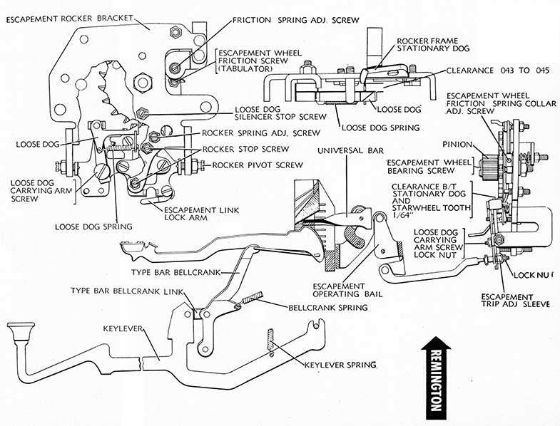
REMINGTON
1. The Escapement Action in the Remington #17 is motivated by the cam shape of the Typebar heel which contacts the lip of the Universal Bar as the type head nears the platen, moving the Universal Bar back to engage the Escapement Operating Bail Roller. As the top of the Escapement Operating Bail moves backward with the Universal Bar, the lower extremity of the Operating Bail moves toward the front of the machine, drawing with it the lower extension of the Escapement Rocker. In this movement the loose dog is disengaged from the Escapement Wheel Tooth, causing the escapement trip. As in other machines, the Stationary Dog acts as a safety valve to limit escapement to one tooth in the pinion or rack. The Pinion Wheel is solidly attached to the Escapement Wheel in this machine and does not utilize a Pinion Pawl for back up movement. Instead, the Loose Dog acts as a wheel pawl in permitting the escapement wheel to move backward as the carriage is moved to the right.
When the Carriage Release Lever is depressed, the Carriage Release Blade acts on the Escapement Loose Dog Release to release the loose dog from contact with the Escapement Wheel Tooth permitting free movement of the carriage. The Rack is permanently engaged in the pinion.
When the Tabulator Lever is depressed, the tabulator blade acts on the Escapement Loose Dog Release to release the Loose Dog from contact with the Starwheel tooth, permitting free movement of the carriage, subject to the braking of the Escapement Wheel by the Escapement Wheel Friction Screw.
2. ADJUSTMENTS:
a. Escapement Trip:
(1) Master Trip Adjustment:
(a) Determine that the Universal Bar, the Escapement Operating Bail and the Escapement Rocker are free on their pivots, with a minimum of end shake. Move a typebar to the platen with the fingers. Escapement trip should take place when type head reaches a point between 1/8" and 1/16" from the platen. Adjustment is made by loosening Lock Nut and turning Escapement Trip Adjusting Sleeve. Turning Escapement Trip Adjusting Sleeve clockwise will cause escapement to trip when type head is farther away from the platen. Turning sleeve counterclockwise will cause escapement to trip when type head is closer to the platen. Tighten lock nut after making this adjustment.
(b) When resetting the escapement trip, turn the escapement wheel to determine the amount of hold the Loose Dog Silencer has in its position on top edge of loose dog. If Trip Adjustment positions Loose Dog too far forward on Escapement Wheel tooth, it may prevent Silencer from engaging loose dog properly. (See Escapement Loose Dog (2).)
(c) After adjusting Escapement Trip, hold type bar to the platen with the fingers and check lower part of escapement rocker for minimum additional forward movement. Make same test with Space Bar depressed instead of type bar held to platen. The Upper Rocker Stop Screw should be adjusted to permit this minimum additional movement.
(2) Individual Trip Adjustment:
Refer to Universal Bar.
b. Escapement Unit. Because of the difference between the number of teeth in the Elite Pinion and Elite Starwheel, there is a special procedure for removing the Escapement Unit and
the Carriage from Elite (12 pitch) machines to prevent affecting the setting of the Racks and Scales, which differs from the method of removing the Escapement Unit and Carriage from the Pica (10 pitch) machines which have the same number of teeth in both the Pinion and Starwheel.
(1) To Remove Escapement Unit from PICA-10 Pitch Machines, remove Rear Snap-on Cover Plate, loosen Escapement Link Lock arm Screw, opening arm to disconnect Escapement Trip Adjusting Sleeve. Remove Rocker Bracket Screw on Lock Nut on the right and Rocker Bracket Binding Screw on the left. Remove the Escapement Unit from the machine.
(2) To Remove Escapement Unit from ELITE-12 Pitch Machines, move the carriage to the extreme left with the right carriage end limiting against its stop screw. Mark the Escapement Wheel Tooth and the Rack Tooth so that in replacing the Escapement Unit, the Escapement Wheel tooth can be lined with the Rack Tooth. Continue removal of Unit as specified under Paragraph (1) above.
(3) To Replace Escapement Unit in PICA-10 Pitch Machine, replace Unit to frame, replacing and tightening Bracket Set Screws and Lock Nuts. Connect Escapement Trip Adjusting Sleeve into Escapement Rocker opening, replacing Escapement Link Lock Arm and tighten screw.
(4) To Replace Escapement Unit in Elite-12 Pitch Machine, line up the marks on the Escapement Wheel and Rack tooth, previously made. Connect Escapement Trip Adjusting Sleeve into Escapement Rocker opening, replacing Escapement Link Arm and tightening screw. Replace Unit to frame, replacing and tightening Bracket Set Screws and Lock Nuts.
(5) To Install New Carriage in Elite-12 Pitch Machine, line up the Escapement Wheel with the large hole directly under the small hole, and the small hole lined up with the small hole in the Escapement Bracket. The Loose Dog should seat fully on the face of the Starwheel tooth directly below large hole in the Star-wheel when holding the starwheel firmly engaged to the Loose Dog with this tooth. If the Loose Dog does not seat fully on the face of the Starwheel Tooth, adjustment may be made by loosening Rocker Pivot Lock Screw nuts and coming in with one screw while going out with the other until the Loose Dog is positioned properly. Check Starwheel to determine, after adjusting, that small top hole in Starwheel is still lined up with the small hole in Bracket. Inserting a pin or rivet in the small top hole in Starwheel, flush with the Star-wheel edge and entering into the small hole in Bracket, move the carriage to the left (viewing machine from the rear), by releasing the Carriage Release Key, until the right end of the carriage limits against the Carriage Stop (release left margin to accomplish this position, if necessary). Holding the carriage in this position, replace Escapement Unit. Connect Escapement Trip Adjusting Sleeve into Escapement Rocker Opening, replacing Escapement Link Arm and tightening screw. Replace and tighten Bracket Set Screws and Lock nuts. Remove the pin or rivet in the small top hole in Starwheel and check position of front scale which should he set at zero "0."
c. Escapement Rocker:
(1) Removal and replacement. To remove Escapement Rocker, remove one Rocker Pivot Screw after
(Continued on page 82)
79
80
ROYAL
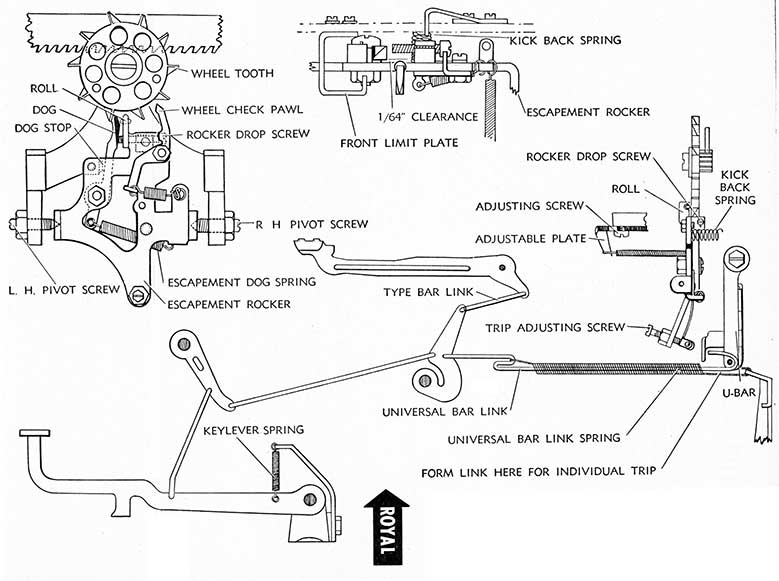
1. The Escapement Action in the Royal Typewriter is motivated by the Universal Bar which is pulled forward by the action of the keylever and link to contact the rocker at the point of the trip roller, opposite the trip adjusting screw. Continuing its forward movement with the rocker, the dog is disengaged from the escapement wheel tooth at the same instant the typebar is making its impression. The escapement wheel commences to rotate immediately after this action, during which interim the escapement roll has resumed its neutral position and the dog has returned to position to stop the next escapement wheel tooth. The escapement roll serves the purpose of holding the escapement wheel in the event the keylever is held down or in the event the space bar is held down. In all other cases it acts as a safety valve to limit escapement to one tooth in the pinion or rack.
2. ADJUSTMENTS:
a. Escapement Trip:
(1) Master Trip Adjustment: Determine that the Universal Bar is free on its bearings and that the Universal Bar Links are hooked properly on the Universal Bar Rod. Move several typebars across the Keyboard toward the platen with the fingers; the escapement trip should take place when the type head is approximately 3/8" from the platen. Adjustment of the Escapement Trip is accomplished after loosening the Trip Adjusting Screw Lock Nut; turning the Trip Adjusting Screw clockwise (to the right) will cause escapement to trip when type head is farther away from the platen. Turning it counterclockwise (to the left) will cause escapement to trip when type head is closer to the platen. Tighten trip adjusting screw lock nut after adjustment has been made.
(2) Individual Trip Adjustment. The Universal Bar Links should be positioned properly on the Universal Bar Rod. When a single typebar is out of trip escapement with the balance of the keyboard, it may be brought into uniformity by forming the Universal Bar Link at point indicated on drawing. Forming the end of link upward (shortening) will cause the escapement to trip when type head is farther away from the platen. Forming the end of link downward (lengthening) will cause the escapement to trip when type head is closer to the platen. Inspect the Universal Bar Link Spring for condition after this adjustment has been made.
b. Escapement Rocker:
(1) Removal and Replacement. Remove Bichrome Vibrator Link Screw (see Ribbon Cover Drawing); disconnect Escapement Rocker Spring from Adjustable Plate; loosen R. H. Pivot Screw Lock Nut and back out R. H. Pivot Screw until Escapement Rocker can be removed from the L. H. Pivot. Escapement Rocker may now be dropped down and removed through base of machine.
To replace, return rocker to its L. H. Pivot; screw in R. H. Pivot Screw to position to free movement of the rocker without binding and without excessive end play. Tighten R. H. pivot lock nut. Replace Bichrome Ribbon Vibrator Link Screw.
(2) Escapement Dog. The Escapement Dog is attached to the Rocker frame with fulcrum screw and lock nut and its position and side play are controlled by the use of a washer between the dog and the frame.
Clearance between the Escapement Dog and Escapement Roll of 1/64" must be maintained. The thickness of the Escapement Dog Washer controls this clearance. The Escapement Dog must be free on its pivot without excessive side play between the dog and rocker frame. Adjustment is made with Escapement Dog Pivot Screw and nut.
The escapement dog must be flush with the escapement wheel tooth. Adjustment is made by forming the Front Limit Plate on late model Royals and by adjusting Front Limit Screw on earlier models.
The Rocker Drop Screw controls the forward movement of the Escapement Dog. The spacing between the Escapement Dog in normal position (holding escapement wheel tooth) and the pick up of the same escapement wheel tooth by the Escapement Roll when the keylever or space bar is held depressed as reflected by movement of the carriage should be approximately 1/32". Adjustment is made with the Rocker Drop Screw. Turning screw clockwise will increase the movement of carriage while turning screw counterclockwise will decrease the movement.
The Escapement Dog Spring must have sufficient tension to return escapement dog to position instantly after releasing escapement wheel tooth.
(3) Escapement Roll. The Escapement roll on the Royal Typewriter performs the function of the stationary or rigid dog used on other machines. The Escapement Roll Roller must free on its bearing and the clearance between the Escapement Dog and Escapement Roll of 1/64" is essential.
(4) Limit Plates. Late model Royal Typewriters are equipped with Front and Rear Limit Plates which are adjusted by forming the plates. Older model Royals are equipped with Front and Rear Limit Screws to provide these adjustments. Rear limit screw or plate should be so adjusted that there is a minimum of additional play in the rocker when the typebar is held to the platen. Limit plates or screws should be adjusted so that Loose Dog edge is flush with edge of Escapement Wheel tooth.
(5) Rocker Pivots. The Escapement Rocker must be free on its pivots with a minimum of end shake. L. H. Pivot Screw is adjusted in the event facing of the Escapement Dog does not seat squarely on face of Escapement Wheel Tooth when the Escapement Dog is in normal position (holding escapement wheel tooth). End shake is taken up with R. H. pivot screw.
(6) Rocker Springs. Late model machines are equipped with a front rocker spring and a rear kick back spring. Front rocker spring tension is controlled by Adjustable Plate held in place by Adjusting Screw. On machines equipped with both springs, the Adjustable Plate should be set back (towards rocker) in its lowest position, unless extremely heavy action is desired. On earlier model machines equipped with front rocker spring alone, the adjustable plate should be adjusted so that spring has sufficient tension to return rocker to inactive position.
3. ESCAPEMENT TROUBLES:
a. Skipping. Before making any adjustments for skipping, check all of the contributing causes listed on Page 77.
(Continued on page 83)
81
82
REMINGTON (Continued from page 78)
loosening lock nut. Remove Escapement Rocker, being careful not to lose Escapement Rocker Spring which is positioned behind the top part of the Rocker on Rocker Spring Adjusting Screw.
To replace Escapement Rocker, return Rocker Spring to its position on Rocker Spring Adjusting Screw. Return rocker to Bracket. Replace Rocker Pivot Screw and lock rent, positioning rocker to provide free movement without bind or without excessive end shake.
(2) Escapement Loose Dog. The Loose Dog on the Remington #17 is formed differently from that on other machines, hinging on the Loose Dog Carrying Arm and positioning in Loose Dog Guide. It functions both as an Escapement Holding Dog and as an Escapement Tooth Pawl. In the latter case, as Escapement Wheel moves backward when returning carriage to right the Loose Dog Silencer moves into position contacting back of the head of the dog, moving the dog down to permit the Escapement Wheel tooth to pass. The upward movement of the dog is limited by forming of the loose Dog Guide.
The Loose Dog should move freely down and up in the guide as well as toward the Escapement Wheel tooth, when pressure of the Escapement Wheel Tooth is released. The Loose Dog Spring should provide proper tension to hold contact lip of the Loose Dog in position to engage Escapement Wheel Tooth (up). Pressure of the Escapement Wheel against contact lip of the Loose Dog positions Loose Dog properly against its limit plate.
Clearance between the Loose Dog and the Rocker Frame Stationary Dog must be maintained at .043" to .045". Clearance between the Loose Dog and Rocker Frame Stationary Dog is controlled by the Loose Dog Guide, three sizes being manufactured for replacement purposes to secure this adjustment.
The front edge of the Loose Dog should be positioned .015 to .020" to the rear (back) of the front edge of the Escapement Wheel tooth. Adjustment is made by loosening lower Escapement Rocker Stop Screw nut and adjusting Rocker Stop Screw. Tighten nut when adjustment has been made.
The face of the Loose Dog should position fully
on the face of the Escapement Wheel Tooth. Adjustment is made by loosening Rocker Pivot Screws and Lock Nuts, and coming in on one screw, going out on the other, until face of the Loose Dog (held to its limit plate by pressure of the Escapement Wheel) is properly positioned. Pivot screws should be adjusted to provide snug fit to Rocker without binding.
(3) Loose Dog Silencer. The Loose Dog Silencer functions to eliminate noise by moving the Loose Dog clear of the Escapement Wheel Teeth when carriage is moved to the right. It should be adjusted to apply a minimum of tension. Adjustment is made by removing Loose Dog Silencer Stop Screw and Nut and loosening Escapement Wheel Friction Spring Collar Adjusting Screw, and adjusting the collar which is threaded. Caution: Do not tighten collar too tight as' it may affect speed of carriage. Tighten Escapement Wheel Friction Spring Collar Adjusting Screw. Replace Loose Dog Silencer Stop Screw, determining that it is positioned through slot in Loose Dog Silencer. Check collar to see that rear side does not extend beyond the edge of Escapement Wheel.
(4) Escapement Rocker Spring. Escapement Rocker Spring Tension Adjusting Screw may be adjusted to provide tension for proper return of rocker to normal position.
(5) Escapement Safety Zone. Raise a center type bar to the platen slowly by hand until escapement trips (which should be when type head is about 4" from platen). When trip has taken place, return type bar towards nest slowly to .determine back trip of the Escapement to complete the cycle. This' return trip should take place when the type head is from 1/2" to 9/16" from the ribbon. As the complete forward and rear trip of the Escapement action is determined by
the width of the escapement wheel teeth, if the return trip takes place when the type head is more than 9/16" from the ribbon, it is possible that in the increased spacing another type bar could move in and print on the same escapement, causing piling or crowding. Adjustment is made by setting the Type Bar Trip further away from the Platen by adjusting Trip Adjusting Sleeve (See 2a (1)).
83
ROYAL (Continued from page 80)
If all of the listed causes are rejected the trouble may be located in one of the following causes:
Clearance between Escapement Dog and Escapement Roll exceeds 1/64". Adjustment is made by installing a thinner washer between Escapement Dog and Rocker Frame.
Escapement Drop is more or less than 1/32". Adjustment is made with Rocker Drop Screw.
Escapement Springs provide insufficient tension. The kick back or front spring must have sufficient tension to return the rocker to position promptly. Adjustment is made with Adjustable Plate or increasing tension (by spreading) Kick Back Spring. Escapement Roll Roller binding on pivot. Adjustment is made by cleansing, if necessary, and lubricating or replacing roller. Escapement Dog not located flush with escapement wheel tooth. Adjustment is made by forming Front Limit Plate or adjusting Front Limit Screw.
b. Piling or Crowding. Before making any adjustments for piling or crowding, check all of the contributing causes listed on Page . If all of the listed causes are rejected the trouble may be found in one of the following causes:
Insufficient clearance between Escapement Dog and Escapement Roll. Clearance must be 1/64". Adjust by placing thicker washer between Escapement Dog and Rocker Frame.
The Escapement Dog binding or loose on its pivot. Adjustment is made with the Escapement Dog Pivot after loosening lock nut.
Rocker Drop Screw not adjusted properly to permit 1/32" drop or movement of carriage. Adjustment is made with Rocker Drop Screw.
Wheel Check Pawl binding or not clearing escapement wheel tooth properly. Adjustment is made with Wheel Check Pawl Pivot Screw after loosening lock nut. Wheel Check Pawl Spring should provide sufficient tension.
84
UNDERWOOD
1. The Escapement Action of the Underwood Typewriters #5 and #6 is motivated by the cam shape of the Typebar heel, which contacts the lip of the Universal Bar as the type head nears the platen, moving the Universal Bar back to engage the Trip Adjusting Screw on the Escapement Rocker. Further movement backward disengages the Loose Dog from the Escapement Wheel tooth causing the escapement trip, which takes place after the impression has been made. The Universal Bar is attached to the Rocker Arms on either side of the Escapement Rocker and at the same time the top of the Escapement Rocker moves back under pressure of the Universal Bar, the top of the Rocker Arms moves back. The Rocker Arm Extension (lower) moves forward (toward the front of machine) and performs the functions of motivating the Ribbon Feed, tripping escapement for the Space Bar and providing Line Locking Mechanism by locking the Escapement Rocker action when engaged by the Key Lever Lock Slide Arm Link lip. When the Typebar is released, the U-Bar Spring and Rocker Spring return the Universal Bar and the Rocker Arms to normal position.
2. ADJUSTMENTS:
a. Escapement Trip:
(1) Master Trip Adjustment:
Determine that Universal Bar Lip is positioned properly in Segment groove and that Universal Bar Guide is positioned centrally in segment slot, and is free on its pivots. (See Universal Bar.) Move a typebar to the platen, with the fingers. Escapement trip should take place when type head reaches a point approximately 1/8" from the platen. Adjustment is made after loosening Trip Adjustment Screw Lock Nut; turning Screw clockwise will cause escapement to trip when type head is farther away from platen. Turning Screw counterclockwise will cause escapement to trip when type head is closer to platen. Tighten Lock Nut when adjustment has been made.
(2) Individual Trip Adjustment:
Refer to Universal Bar Adjustments.
b. Escapement Rocker:
(1) Removal and Replacement. Remove Carriage (see Main Carriage). Disconnect Loose Dog Spring. Facing machine from the rear with Tabulator Housing and cover plates removed, loosen the Escapement Rocker Pivot Set Screw on the right. Back out the Rocker Pivot by pushing Rocker to the Right. The Escapement Rocker (dogs assembled) may now be removed.
To Replace, reverse above procedure.
(2) Escapement Loose Dog. Clearance between the Loose Dog and the Rigid Dog must be maintained at .052" to .055". Adjustment is made by stoning or grinding Loose Dog at point it abuts against Escapement Rocker to reduce clearance or by forming top part of Loose Dog to increase clearance. Care should be taken not to bend Loose Dog Pivot. The Loose Dog should move freely on its pivot and Loose Dog Spring should provide sufficient tension but not in excess of amount required to return dog to position. Adjustment is made by loosening Loose Dog Spring Support Screw and positioning spring support. Tighten Spring Support Screw when adjustment is made.
Loose Dog Stop should be adjusted so that when holding a type bar against platen there will be .025" clearance between back edge (opposite face) of Loose Dog and the back edge of Escapement wheel tooth just passed.
Rigid (Stationary) Dog. Clearance between the Rigid Dog and Escapement wheel tooth when the Escapement wheel tooth is held directly behind the Rigid Dog must be maintained at .025". Adjustment is made with Rigid Dog Adjustment Screw.
Rigid Dog Check Screw. Holding typebar against Platen, clearance between Rigid Dog Check Screw and Escapement Frame must be limited to 1/64". Press in lower extension of Rocker to determine this clearance. Adjustment is made with Dog Rocker Limit Screw.
85
86
WOODSTOCK
1. The Escapement Action in the Woodstock Typewriter, above 580,000 serial, is motivated by the Lower Universal Bar which is connected to the Escapement Rocker by an Extension Arm, Dog Rocker Link and Trip Adjusting Sleeve. Teeth of the Lower Universal Bar are positioned directly below their respective keylevers and as the keylever is depressed, the Universal Bar moves downward. As the Typebar, which is motivated in the same action by the Keylever, Sub-lever and Typebar Link, reaches a point between 3/16" and 1/4" from the platen, the trip adjusting sleeve, on its forward movement carrying the lower part of the Escapement Rocker, causes the Loose Dog (which holds the Escapement Wheel Tooth in normal operation) to become disengaged from the Escapement Wheel Tooth permitting the one-escapement trip. The Stationary Dog, acting as a safety valve, limits the trip or escapement to one tooth in the pinion or rack. The Universal Bar Spring and Escapement Rocker Spring cooperate in returning the Universal Bar to normal position after a keylever has been released, while the Keylever Tension Spring returns the type bar to the next position.
2. ADJUSTMENTS. Before attempting adjustments, determine that sub-frame screws (located in frame opening under carriage) are tight.
a. Escapement Trip:
(1) Master Trip Adjustment. Determine that the Lower Universal Bar is free on its pivots with a minimum of end play. Move several different typebars across the keyboard to the platen with the fingers; the escapement trip should take place when the type head is approximately 3/16" to 1/4" from the platen. Adjustment of the Escapement Trip is accomplished after loosening the Trip Adjusting Sleeve Nut. Turning the Trip Adjusting Sleeve clockwise (to the right) will cause escapement to trip when type head is farther away from the platen. Turning the Trip Adjusting Sleeve counter-clockwise (to the left) will cause escapement to trip when type head is closer to the platen. Tighten lock nut after adjustment has been made.
(2) Individual Trip Adjustment. The teeth of the Lower Universal Bar in the Woodstock Typewriter, above 580,000 serial, are formed only for individual trip adjustment. If the trip on several keylevers on the right or left side of the keyboard is opt of adjustment with the balance of the keyboard, the Lower Universal Bar should be inspected to determine if it is bent at that end. If so, the main U-Bar should be straightened. When a single type bar is out of 'trip escapement with the balance of the keyboard, it may be brought into uniformity by forming the tooth of the Lower Universal Bar contacted by that keylever. To bend the tooth upward will cause the trip to break when the type bar is farther away from the platen; to bend the tooth downward will cause the trip to break when the type bar is closer to the platen.
b. Escapement Rocker:
(1) Removal and Replacement. Facing the machine from the rear remove the rear cover plate(s). Loosen the Dog Rocker Pivot screw lock nut on the right and back out the pivot screw. Loosen the Trip Adjusting Sleeve Lock Nut and remove both the lock nut and the Trip Adjusting Sleeve from the Dog Rocker Link (which protrudes through rocker slot). Drop the escapement rocker and disconnect from the Space Wire, being careful not to lose small washers on pivot screw on the left. Disconnect the. Rocker Spring.
To Replace. Connect the Space Wire. Raise the Escapement Rocker feeding the Dog Rocker Link through its slot in the Rocker as the rocker is placed on the pivot to the left (be sure the small washers are in their proper positions on the pivot screw). Tighten the rocker pivot screw on the right, positioning the rocker properly, leaving a minimum of end shake to prevent rocker from binding. Tighten pivot screw lock nut. Replace Trip Adjusting Sleeve and lock nut, setting Escapement Universal Trip as outlined in Paragraph 2 a above. Connect the Rocker spring. Tighten Trip Adjusting Sleeve Lock Nut.
(2) Loose Dog. The Loose Dog is attached to the rocker frame by pivot screw and lock nut (on reverse side). To remove, back out pivot screw lock nut, then back out pivot screw. Disengage loose dog spring and dog link as the loose dog is removed from the rocker frame. The Loose Dog should be free on its pivot and the dog link should limit the movement of the dog as well as act as a shock absorber. Facing machine from the rear, the near edge of the loose dog should be flush with the edge of the escapement wheel tooth. Adjustment is made with the Upper Limit Screw. The face of the loose dog should seat fully on the face of the escapement wheel tooth. Adjustment is made with the rocker pivot screw on the left, moving the rocker to the left or right until the loose dog facing seats fully on the escapement wheel tooth. Tighten both rocker pivot screw lock nuts when the adjustment has been accomplished.
(3) Stationary Dog. The Stationary Dog is attached to the rocker frame by two binding screws in the oval slotted section of the frame. Clearance between Lip of Stationary Dog tooth edge and Loose Dog tooth edge should be .063" (thickness of the Back Space Plate), which is governed by the thickness of the Stationary Dog Shim located between the dog and the rocker frame. Stationary Dog Lip should lie at the highest position possible on the top edge of the rocker frame. Binding screws should be tight.
(4) Limit Screws. The Upper Limit Screw adjusts the position of the edge of the Loose Dog in relation to the edge of the Escapement Wheel Tooth, which should be flush. The Lower Limit Screw limits the movement of the top of the rocker which should be adjusted to prevent the escapement wheel tooth from rubbing on the body of the Stationary Dog. Holding a typebar against the platen with a keylever, there must be a minimum of extra play in the rocker, otherwise a strain upon the tooth of the lower Universal Bar will throw the escapement trip out of adjustment.
(5) Dog Link. The Dog Link limits the movement of the Loose Dog, and acts as a shock absorber.
(6) Rocker Spring. Older model Woodstock typewriters utilize a compression spring placed beneath the lower limit screw. Woodstock typewriters above 580,000 utilize rocker spring shown in drawing. If disconnected, skipping or piling may occur. Manufacturer's spring provides the proper tension. To increase spring tension will increase the touch; to provide a longer spring will cause sloppy action of the rocker.
(7) Back Lash Pawl: (See Back Spacer.) The Back Lash Pawl should be positioned so that it does not catch on the edge of the Escapement wheel tooth. It functions in connection with the Back Spacer.
(Continued on page 90)
87
88
L. C. SMITH
1. The Escapement Action in the L. C. Smith typewriter is motivated when the keylever is depressed by the action of the Sub-lever upper extension moving back to contact the Universal Bar (which is securely attached to the lower extremity of the Escapement Rocker). As the Universal Bar moves rearward, the Loose Dog is disengaged from position of the starwheel tooth, which permits one-escapement action. The Rigid Dog serves as a safety valve to limit escapement to one space in the rack. As noted in the drawing, whenever the Universal Bar is motivated (either by the keylever or the space bar), the Escapement Rocker, controlling the Ribbon Cover, moves the ribbon into position to cover the type. When the Carriage Release Lever is depressed, the Carriage Release Bellcrank contacts the Roller on the Carriage Release Bar, moving the bar downward to engage the Wheel Release Bellcrank roller, which, in turn, through the Wheel Release Bellcrank, depresses the Escapement Loose Dog, disengaging it from contact with the Escapement Wheel tooth, permitting free movement of the carriage. When the Tabulator Bar is depressed, tabulator mechanism working through the Wheel Release Bellcrank depresses the Escapement Loose Dog, disengaging it from contact with the Escapement Wheel Tooth and permitting freedom of movement to the carriage subject to braking against the Main Spring Drum by the Tabulator Friction Spring on the drum.
2. ADJUSTMENTS. Before attempting adjustments, tighten Drum Bracket Screws on top Plate. (See Mainspring and Drawband. )
a. Escapement Trip:
(1) Master Trip Adjustment. Release Space Bar Trip Adjusting Screw before adjusting Escapement Trip (see Space Bar). Determine that the Universal Bar and the Escapement Rocker are free on their pivots. It is essential that Universal Bar Adjustments be made in the following order: (1) Trip, (2) Pick-up and (3) Rocker Limit.
(2) The Escapement Trip should take place when a typebar, held by the fingers, is 1/2" from the platen. Adjustment may be made with Trip Adjusting Nuts (2). Loosening Nut on the left (nearest Universal Bar frame) and coming in (turning clockwise) nut on the right will cause the Escapement Trip to take place when the typebar is closer to the Platen. Loosening Nut on the right (rear of Escapement Rocker) and coming in (turning clockwise) nut on the left will cause the escapement trip to take place when the typebar is farther away from the platen.
(3) The Universal Bar Pick-up, by the sub-lever, should take place when type bar is 1 7/8" from the platen on Super-Speed models and 1 5/8" from the Platen on Model #8 machines. As this adjustment affects the Ribbon Shifting Mechanism it is necessary to alter adjustment slightly to permit Ribbon Bichrome Lever to operate freely. Adjustment is made with U-Bar Pick-up Adj. Screw, after loosening Lock Nut.
(4) The Rocker Limit Screw may now be adjusted to permit 1/32" additional movement in the Rocker (with typebar held to the platen). Adjustment may be made with Rocker Limit Screw after loosening Lock Nut.
b. Individual Trip Adjustment:
(1) Where individual trip on a single typebar is not uniform with the balance of the Typebars, trip on that typebar may be adjusted by peening or filing
(whichever is necessary) Universal Bar contact point on that sub-lever. (See Universal Bar.)
(2) Where trip on keylevers at either end of keyboard is not uniform with trip on the other end, the Universal Bar is not positioned parallel with the row of sub-levers. Adjustment may be made after loosening U-Bar Bracket Binding Screws by properly positioning U-Bar Bracket. Tighten Bracket Binding Screws when adjustment is made. (See Universal Bar.)
c. Escapement Rocker:
(1) Removal and Replacement. To remove Escapement Rocker, disconnect Ribbon Pull Arm and remove Escapement Connecting Screw on Universal Bar (to the left of left Trip Adjusting Nut-see Drawing). Loosen right hand Rocker Pivot Screw Nut (facing machine from the rear) and back out Pivot Screw. Rocker may be removed to the right and out. Carriage should be positioned at the extreme left in removing and replacing Escapement Rocker. To replace Rocker, reverse above procedure.
(2) Escapement Assembly. For the benefit of the mechanic in disassembling and assembling the Escapement Rocker, a full view is shown in drawing (facing Escapement Rocker from Rear of machine).
(a) Escapement Loose Dog must be free on its pivot (to move up and down) and loose dog spring must provide sufficient tension to return Loose Dog into Escapement Tooth contact position. Loose Dog must be checked for wear and if worn must be replaced, otherwise skipping will result. Felt Pads in Escapement Assembly must be replaced if beaten thin or if deteriorated with cleaning fluid. The Loose Dog coil spring, positioned behind loose dog in the escapement assembly, for quietness only, must have proper tension. The Loose Dog functions as a Pawl when back spacing, being pushed out of contact position with the Escapement wheel tooth when the carriage is back spaced or returned to the right. The Face of the Loose Dog should position fully on the face of the Escapement Wheel Tooth. Adjustment may be made by positioning the Escapement Rocker on its pivots (moving rocker to left or right as may be necessary). Loose Dog Holder Stud which limits upward movement of the Loose dog, if worn will permit loose dog to move upward too high. Stud may be turned around on Holder to position round side to Dog properly limiting Loose Dog. The Loose Dog must position itself approximately three-fourths on escapement wheel tooth. The edges are not set flush. (See Drawing.) Adjustment is made with the Dog Rocker Limit Screw.
(b) The Rocker Casting is shaped to provide proper clearance between the Loose and Stationary (Rigid) Dogs and there is no adjustment to be made other than replacement of dogs, if worn.
(c) Rigid (Stationary) Dog serves as a safety valve to limit escapement to one-tooth in the rack by limiting Starwheel to individual tooth movement. If face of Stationary (Rigid) Dog is worn, the dog must be replaced. The felt pad, if thinned or deteriorated with cleaning fluid must be replaced. The Rigid Dog coil spring, for quietness only, must provide sufficient tension.
(d) Rocker Spring must provide sufficient tension
(Continued on page 92)
89
90
SPACE BAR
REMINGTON
1. The Space Bar Trip on the Remington Typewriter is motivated by Push Link engaging Escapement Arm when the Space Bar is depressed.
2. ADJUSTMENTS:
a. The Space Bar is set in its proper position when the bottom of the space bar is level with the front center top of the front frame, which adjustment is made by forming the Space Bar Up-Stop. When depressed, the top of the space bar should be level with the front frame corner, which adjustment is made by adjusting Space Bar Down Stop assembly (screw and nut).
b. The Space Bar Shaft should fit snugly on its pivots without binding, and be centered properly. Shaft Pivot Screw and Nut, on either side of machine, afford fitting adjustment.
c. The Push Link should be adjusted so that the Space Key Push Link Roll will be positioned near the front end of the Escapement Arm. Adjustment is made with the Push Link Adjusting Guide.
d. The Space Bar Trip, adjusted by the Push Link Eccentric, should be so set that the Trip will take place when the space bar is within 1/16" of its down stop. If Push Link Eccentric does not afford enough adjustment, Space Key Shaft Arm (attached to Space Bar Shaft and Push Link Eccentric) may be formed by mauling top edge of Arm just behind Shaft for lowering and bottom edge of Arm just behind Shaft for raising.
e. Line Lock Pawl Eccentric should be adjusted so that the Line Lock Pawl locks positively on Line Lock Bail when right margin stop locks the keylevers. Both sets of Line Lock Pawl screws should be tight to prevent noisy operation.
f. To Remove Space Mechanism turn typewriter up on its back, remove Frame Side Support (cross bar), loosen Shaft Pivot Lock nuts and turn in pivots to release Space Bar Shaft. Disconnect Push Link Screw and Push Link Eccentric to disengage Push Link. Disconnect Space Key Spring. Space Mechanism may be moved down, to disengage Space Bar from Space Bar Stop, and out. To Replace Space Mechanism, reverse procedure, adjusting Push Link Eccentric properly.
WOODSTOCK (Continued from page 86)
3. ESCAPEMENT TROUBLES:
a. Skipping. Before attempting any escapement adjustments for skipping, check all the contributing causes listed on Page 77. If all the listed causes are rejected the trouble lies with the clearance between the stationary and loose dog-it is greater than .063". This clearance can be reduced by placing a thinner shim between the stationary dog and the rocker frame. It is also possible to close this gap slightly by bending the stationary dog lip and the loose dog together carefully.
b. Piling and Crowding. Before attempting any escapement adjustments for piling and crowding, check all of the contributing causes listed on Page 77. If all of the listed causes are rejected the trouble may be found in one of the following causes:
Escapement trip too close to the platen or no escapement trip.
Rocker binding on Trip Adjusting Sleeve or Space Bar wire.
Lower Universal Bar binding on pivots.
The Stationary Dog and Loose Dog have insufficient clearance, in which event, dogs may be spread apart by installing a thicker shim between the stationary dog and the rocker frame or the two dogs may be pried apart slightly with screw driver.
c. Shadowing. Older model Woodstock typewriters are equipped with a rocker arm rebound spring with adjustable screw. It is located under the top plate rear, center of machine. Late model Woodstock typewriters depend upon a Typebar Rebound Spring, attached to the segment directly below the type guide. Tension may be increased by bending the top of the spring out, away from, the guide to provide greater resistance against the bar. Increasing keylever tension by keylever adjusting screw will cause quicker kick back of the typebar.
91
92
ROYAL
1. Depression of the Space Bar pulls the Space Bar Link and outer extension of Space Bar Trip Arm forward moving the inner extension of the Space Bar Trip Arm in to engage the top of the Escapement Rocker Plate, causing the loose dog to move off the Escapement wheel tooth, thereby causing escapement. If the space bar is held in down position, the Escapement roll holds the Escapement wheel tooth until released.
2. ADJUSTMENTS:
a. Space Bar Trip. The Space Bar Link Adjusting Nut controls the space bar trip by movement of the Space Bar Trip Arm. In normal position there should be approximately .005" to .010" clearance between Space Bar Trip Arm and Escapement Rocker at point of contact. If clearance is less, Space Bar Trip Arm will prevent Rocker from returning to front Rocker Limit Plate and will affect flush position of Escapement Dog and Escapement Wheel Tooth. To adjust, disconnect Space bar link from outer extension of Space Bar Trip Arm frame and loosen Space Bar Link Adjusting Nut. Turning the link clockwise will move Space Bar Trip Arm contact point closer to escapement Rocker; turning the link counterclockwise will move space bar trip arm contact point away from escapement rocker.
b. The Space Bar Link should be adjusted so that after space bar escapement takes place there will be approximately 1/8" additional downward movement in the space bar before it contacts the Space Bar Stop. Tighten space bar link adjusting nut when adjustment has been made.
c. The Space Bar Keylever must operate freely in keylever comb and keylever segment. Space bar spring must have sufficient tension to return space bar mechanism to normal position after escapement. Space Bar Trip Arm must be free on its pivots.
d. Space Bar Buffer Support is provided with elongated slots for up and down adjustment of stops. Adjustment of space bar link, of necessity, requires adjustment of space bar buffer support to permit of 1/8" downward movement of space bar after escapement has taken place.
Test all screws and nuts for tightness after adjusting.
e. To Remove and Replace. The space bar may be removed from Space Bar levers by turning machine on its back and removing Space Bar Binding Screws. Space Bar Levers may be removed by Backing out Key-lever Fulcrum Rod (using follow-up rod), disconnecting Space Bar Link from Space Bar Trip Arm, levers may be dropped down and out of machine. To replace, reverse above procedure.
L. C. SMITH (Continued from page 88)
to return rocker to normal position after escapement trip and as it also functions to return ribbon vibrator and Universal Bar to inactive position, sufficient tension should be provided to perform these functions without causing a drag of the Rocker in returning. Adjustment may be made with Rocker Tension Adjusting Screw, after loosening lock nut.
(e) Keylever Tension, which is adjusted with
Keylever Tension Spring Adjusting Screw, should be uniform across keyboard, slightly less on keys controlled by the little finger, and when weighed by a 2 ounce weight, with touch control set at zero, should lift the keylever and sub-lever to contact with the Universal Bar (1 7/8" from platen on Super-Speed models; 1 5/8" from platen on late Model #8).
93
94
UNDERWOOD
1. Depression of the Space Bar causes Space Bar Adjusting Lever to contact Rocker Arm Extension. Movement of the Rocker causes the Escapement Trip. After making Space Bar Adjustments with Space Bar depressed, there should be 1/64" clearance between Escapement Rocker and Rigid Dog Check Screw (see Escapement Action).
2. ADJUSTMENTS:
a. Space Bar should be level and in normal non-operating position, the top of Space Bar should be positioned .034" (11/32") below top of lower line keys. Adjust by forming Space Bar Stops and Space Bar Levers.
b. Clearance between tip of Space Bar Adjusting Lever and Rocker Arm Extension in normal non-operating position should be .010 to .020". Adjust with Space Bar Adjusting Lever Screw, as shown in drawing.
c. Space Bar Spring Tension must be sufficient to return space bar to normal position and to eliminate space bar movement when a keylever is depressed. Adjust by loosening Space Bar Spring Adjusting Collar Set Screw and turning collar.
d. Down Stop (On Master Model) is shown in Insert in Drawing. Adjustment for down stop is made by forming Down Stop Extension on Space Levers.
e. Space Bar Levers should clear all depressed key levers. Adjust by loosening Space Bar Screws (under space bar) and move space bar in desired direction, or form Space Levers.
f. To Remove Space Bar Mechanism. Disconnect Touch Adjustment Lever from lever collar by removing binding screw. Release tension on Space Bar Spring Adjusting Collar. Remove front frame Space Bar Stops attached to underside of front frame crossbar. Back out Space Shaft Fulcrum Screws (one on either side of frame opposite space shaft). Space Bar may now be dropped down, the right end swung toward the front slightly to disconnect Touch Adjustment Link, then Space Bar Adjusting Lever may be withdrawn from between Keylevers #21 and #22.
95
96
WOODSTOCK
1. Depression of the Space Bar pulls forward the space wire and the lower extension of escapement rocker to which it is connected on space bar stud, disengaging the loose dog from the Escapement wheel tooth and causing the one-escapement action. The Space Lever Rod is held in place by two pivot screws entering from outside of base frame. At the right end of the Space Lever Rod is a spring washer for the purpose of holding the Space Bar in a central position and eliminating vibration and noise.
2. ADJUSTMENTS:
a. Space Bar Trip. To adjust the trip, see that the bottom extension of the Escapement Dog Rocker is held in its extreme forward position; loosen the two Space Bar Trip Adjusting Screws; pulling the Space Arm back toward the front of machine until all lost motion between the link and escapement Dog Rocker is taken up without straining Space Wire. Tighten the two Trip Adjusting Screws.
b. Spring Adjustment. At the left end of the Space Lever Rod is located the Space Lever Rod Spring Bracket which may be adjusted up or down to obtain the required amount of tension on the Space Bar. Loosen Spring Adjusting Bracket Screw (outer) and move the Space Bar Spring Bracket up or down for less or more tension. Space Bar
Spring is hooked to extension on Spring Adjusting Bracket and to extension on machine base.
c. Stops. Spade Bar Stop Bracket should be adjusted up or down to permit approximately 1/16" downward movement of Space Bar before Space Bar Wire contacts the Dog Rocker. After escapement trip has taken place, there should be approximately 1/16" to 1/8" additional downward movement of space bar before it contacts the Down Stop Bracket felt stop. Adjust by moving Space Bar Stop bracket up or down on its binding screws. Form Space Bar Stops if necessary.
d. Space Bar Assembly. To remove disconnect Space wire by backing out Space Bar Trip Adjusting Screws and moving Space Arm toward back of machine. Disconnect Space Wire from its position on Escapement Rocker space wire stud. Disconnect Space Bar Spring. Remove Space Pivot Screws from outside of frame, both sides, being careful not to lose Space Bar Rod Washer.
To Replace. Feed the Space Arm up between Key Levers Nos. 25 and 26. Attach Space Wire to Dog Rocker Stud. Return Space Rod to position in frame, replacing space bar rod washer and returning Pivot screws. Connect Space Bar spring. Readjust Space Bar Trip as specified in 2a above.
L. C. SMITH
1. The space key levers are connected to the Universal Bar, through the space bar link (one on each space key lever) and the space bar is fitted to the key lever fulcrum and tensioned by its own key lever springs and adjusting screws for each of the two space key levers. The space bar trip is accomplished by movement of the U-Bar through the action of the space bar links. Space bar trip adjustment should be made after Escapement Trip and pick-up adjustments have been perfected.
2. ADJUSTMENTS:
a. The Space Bar should be level and should be adjusted to permit 1/8" downward movement on each space key-lever before picking up the U-Bar and 1/16" further downward travel after U-Bar trip is completed. Adjustment may be made after loosening space bar trip adjusting screws (on each side of U-Bar), moving adjusting arm up or down as may be necessary. Adjusting arms should be parallel
with each other for proper operation. Tighten space bar trip adjusting screws and test U-Bar trip. Space bar up-stops should be formed to position space bar up travel properly.
b. Space Bar Springs should be adjusted to provide sufficient tension to return space bar to normal inactive position when space bar is released. Adjustment is made with space bar keylever spring adjusting screw.
c. Space keylevers must be parallel and with space bar in inactive position both must position space bar to contact up-stops. Adjust by peening space keylever to parallel.
d. To remove space bar mechanism, release space bar link from space keylever. at connection shown on side of key-lever in drawing. Remove space lever spring adjusting screws. Space levers may now be disengaged from keylever fulcrum and space mechanism removed.