GENERAL
SECTION 1-Exercise Head
SECTION 2-Air-Flask Section
SECTION 3-Afterbody-Removal of Major Units from
SECTION 4-Afterbody, with Parts Assembled to Shell
SECTION 5-Valve Group and Superheater
SECTION 6-Main Engine
SECTION 7-Starting Gear
SECTION 8-Depth Mechanism, Gyro Mechanism, and Gyroscope
SECTION 9-Tail Cone Assembly
SECTION 10-Afterbody-Assembly and Test
SECTION 11-Assembly of Afterbody on Air Flask
GENERAL
1. The instructions contained in the Bureau of Ordnance Manual set forth the prescribed methods for care and handling of torpedoes and torpedo tubes aboard ship. The instructions contained in this Manual have the full force of Navy Regulations. In addition to the Bureau of Ordnance Manual, instructions in the form of NavOrd Circular Letters, Naval Ordnance Technical Information, and NavOrd Ordalts are issued by the Bureau of Ordnance as required for the proper care and handling of, or changes in, torpedoes and torpedo equipment. The personnel responsible for torpedoes on board ship must familiarize themselves with the contents of the publications referred to above in order to comply with the instructions contained therein.
2. The purposes to be accomplished in the periodic overhaul of a torpedo are as follows:
(a) Clean all the torpedo parts.
(b) Examine all parts for defects.
(c) Renew or repair defective parts.
(d) Make proper assembly of the parts.
(e) Test the individual mechanisms.
(f) Test to check the proper functioning of the torpedo as a whole.
(g) Properly treat the parts to preserve them from deterioration.
3. Many years of torpedo experience under normal service conditions have indicated the advisability of a centralized overhauling station (ship) for all types of vessels. Uniform methods, complete knowledge of the torpedo and adequate tools and testing equipment, including competent personnel, are requisites to proper overhaul and can better be materialized in a centralized overhauling station (ship) than in all the various vessels in the service which carry torpedoes. Uniformity in method insures the use of the best method under all circumstances; complete knowledge of the torpedo is a guarantee of the completeness of overhaul; adequate tools and testing equipment provide the assurance that when overhaul is completed, a satisfactory service run will be obtained; competent personnel insures rapidity of accomplishment of high grade work. The tools issued for the
140
overhaul may be the finest, and the very best methods of overhaul may be prescribed, but both may fail to produce results if the personnel is not up to the necessary standard. The necessary standard of personnel not only entails a complete knowledge of a torpedo, but also includes mechanical ability.
4. This chapter covers all the steps necessary for normal disassembly, overhaul, assembly, and tests. Completion of these steps will place the torpedo in a "Ready" condition (ready for adjustments preparatory for firing).
5. The tools for each operation are listed. Tools so listed are grouped under the following headings:
(a) Torpedo Tools
(b) Workshop Equipment Tools
(c) Special Testing Fixtures
Tools listed under (a) above are sufficient to allow disassembly, emergency repairs or adjustments, and the application of the preliminary and final adjustments before firing. Tools listed under (b) above are for exclusive use in the torpedo workshop for major overhaul and for fitting renewal parts when necessary. Workshop equipment tools are designated by the prefix "WE" before the tool number.
Fixtures listed under (c) above are used for testing the individual units of a torpedo
prior to assembling in a torpedo. Description of and instructions for the use of these fixtures will be found in OP 1217, which supersedes OD 750.
6. All asbestos gaskets (except the nozzle gasket on turbine bulkhead) and their flanges should be treated with gasket sealing wax to minimize leakage of sea water into submarine torpedoes. The procedure for applying gasket sealing wax is as follows:
(a) Clean holding surfaces.
(b) Heat gasket sealing wax to molten state (approximately 200 degrees Fahrenheit).
(c) Coat holding surfaces evenly by painting on hot wax with a brush unless metal is cold. If metal is cold, use a hot soldering iron to obtain a good bond.
Caution: Do not allow wax to drip into intricate parts of the torpedo.
(d) Dip gaskets into wax and allow excess to drip off.
(e) Place gaskets on flanges and seal opening. Tighten holding nuts or screws evenly all around.
7. Throughout the text of Chapter 8, steps preceded by an asterisk (*) will be found. These steps should be carried out only if necessary to repair or renew parts which are not normally removed or disassembled in the course of overhaul.
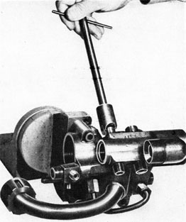
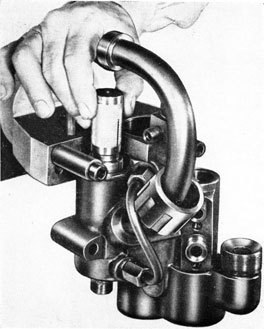
2. Push head just clear of air flask and disconnect (at exercise head nipple) the air pipe which connects air-flask blow valve to exercise head. (141A)
B. Remove Air-Releasing Mechanism
1. Remove holding nuts and cover for air releasing mechanism, and lift mechanism clear of head. (48)
2. Disconnect air pipe, and remove mechanism and gasket. (141A, 229)
C. Remove Bulkhead
1. Remove nuts holding bulkhead and withdraw bulkhead from exercise head with air-releasing mechanism pipe attached. (48, 61)
2. Remove gasket from bulkhead seat.
*D. Remove Air-Releasing
Mechanism Pipe
1. Loosen pipe clip screw to free pipe. (41)
2. Disconnect and remove pipe from bulkhead. (141A)
E. Remove Torch Case
1. Remove nuts securing torch case cover. (48)
2. Remove torch case cover, torch case, and gasket.
F. Remove and Disassemble
Water-Discharge Valve(s)
1. Remove holding nuts and spring plate (s). (48)
2. Remove valve (s) and spring (s).
*3. Slip Tool No. 241A-242A over valve assembly; clamp assembly in vise jaws and remove valve nut and leather washer.
(448, 241A-242A)
Note: Leather washer should be discarded if cracks, hardness, or verdigris are present.
G. Disassemble Air-Releasing Mechanism Mk 2
1. Remove adjusting nut cap and washer, adjusting nut keep screw, and adjusting nut. (141A, 41, 18)
2. Remove spring and spring support.
3. Remove bottom nipple, washer, and valve. (141A, 18)
H. Disassemble Air-Releasing Mechanism Mk 3
1. Unscrew adjusting nut cap and washer adjusting nut keep screw, and adjusting nut. (141A, 41, 18)
2. Remove spring and spring support.
3. Remove bottom nipple and washer. (451, 229)
4. Remove air strainer.
5. Remove strainer holder and washer. (451, 229)
6. Remove valve.
I. Disassemble Headlight Mechanism
1. Remove batteries to charge:
Note: Batteries should be charged after every run in which headlight is used.
(a) Unscrew headlight casing.
(b) Remove four batteries.
(c) Charge batteries. (See OP 1217 for charging procedure).
*2. Remove bulb:
Note: Bulb should be replaced after it has been used for 15 runs.
(2) Disconnect spring; remove nut, wire with connection, cotter pin, washers, and switch lever. (435, 92)
(3) Unsolder wire from bulb socket; remove screws, and remove bulb socket. (41)
(4) Remove screws, bulb contact, and insulator under bulb contact. (41)
(d) Remove bottom plate assembly:
(1) Unsolder wires from bottom contacts.
(2) Unsolder nut securing bottom-plate assembly to central support rod.
(3) Remove nut, bottom plate assembly, key, and conduits. (141A)
(4) Remove phenolic bottom and insulator from bottom plate.
(e) Remove upper contacts:
(1) Remove phenolic top assembly from central support rod.
(2) Unsolder wires from upper contacts.
(3) File pins for contacts; drive out pins; remove contacts and springs.
J. Remove Marker Bomb From War Exercise Head
1. Remove nuts and ring securing marker bomb in place. (48)
2. Withdraw marker bomb from head.
3. Unscrew water cap from marker-bomb stock and withdraw spherical rubber packing and leads to expose taped connections.
4. Remove tape and unsolder connections.
K. Remove Marker-Bomb Switch from War Exercise Head
1. Disconnect lead to switch from battery terminal. (435)
2. Remove tape and disconnect lead from switch to marker bomb lead passing through gland in exploder casing.
3. Remove two nuts (port and starboard) and washers holding switch in casing. (48)
4. Withdraw switch from casing.
L. Remove Battery Assembly from
War Exercise Head
1. Disconnect lead to marker bomb from battery terminal. (435)
2. Remove two nuts and lock washers holding battery assembly in casing. (48)
3. Remove battery assembly from casing.
The above completes the disassembly of the Exercise Head.
OVERHAUL, ASSEMBLY
AND TESTS
*M. Replace or Resolder Studs for Bulkhead and Flanges
1. Apply heat to stud until stud will unscrew with screw driver. (41)
2. Tin new stud and screw in place when hot; wipe excess solder off threads with rag and chase thread on screw with 1/4-inch x 20-finger die. (442, 490)
N. Treatment of Interior of Head
1. Clean interior of head thoroughly.
2. treat exposed surfaces with a protective coating of preservative (J).
*O. Lead Ballast
1. Should necessity arise for the removal and re-installation of lead ballast, due to corrosion under ballast or removal of dents in shell, the ballast must be replaced in exact location from which removed.
2. Shell having been cleaned and given a heavy coating of tin, replace lead weight and solder in place using soldering iron.
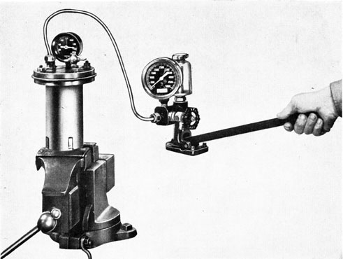
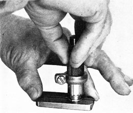
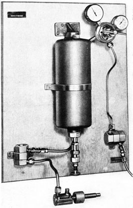
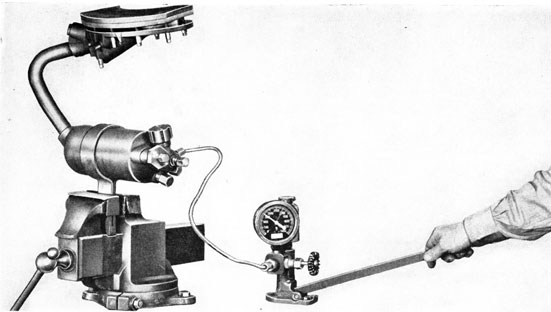
P. Torch Case
(Fig. 133A).
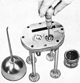
1. Clamp the bottom plate support, of torch case hydraulic test fixture in a vise, and insert torch case to be tested with a gasket on its under side.
2. Fill torch case with water.
3. Place rubber washer on top of torch case.
4. Secure top plate on fixture, using metal washers under nuts. (18)
143
Figure 133A
5. Connect pipe from hydraulic test pump to nipple on top plate. (229)
6. Open pet cock and pump until water appears; then close pet cock.
7. Continue to pump until 135 p.s.i. pressure is obtained. Hold this pressure for five minutes, and examine carefully for leaks. If leaks are present, renew casing unless facilities are available for effective repairs.
8. Disconnect pipe from top plate and remove torch case from fixture. (229, 18)
*Q. Air-Releasing Mechanism Pipe
1. Anneal pipes and bend to shape in accordance with drawings.
2. Reseat seats on pipe collars. (WE86) 3. Reseat nipples for pipes. (WE85)
R. Test Exercise Head for Leaks
*1. If leather washer was removed from water discharge valve(s) during disassembly, work grease (E) into a new washer, assemble new washer on valve, and tighten down with nut. (448, 241A-242A)
1a. If leather washer was not removed from valve (s) during disassembly, work grease (E) into used washer.
2. Clean, inspect, and grease (E) water-discharge valve guide, seat, and studs in valve flange.
3. Grease (E) and insert valve in flange; place gag across studs and secure with nuts, setting up until valve is held firmly on seat. (48)
4. Insert air-releasing pipe into clip, and connect to nipple in bulkhead pocket. (141A)
*5. Tighten pipe clip screw.
6. Install bulkhead.
(a) Thoroughly clean bulkhead seats to remove all dirt, oil, and grease.
(b) Select a new bulkhead gasket, clean and inspect it thoroughly, and place it on bulkhead seat, over studs.
(c) Replace bulkhead and secure with
nuts, tightening up evenly all around.
(61, 48)
7. Connect nipple on bulkhead to source of high-pressure air. Hold forward end of
144
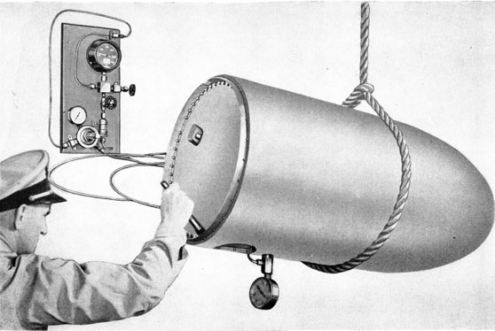
Figure 133B
air-releasing pipe clear of head; turn on air line valve to deliver about 600 p.s.i. pressure, and note flow of air through pipe. If it is suspected that restrictions are present in the air-releasing pipe, they must be located and remedied. Turn off air. (141A)
8. Blank off forward end of air-releasing pipe. (141A, 18)
9. Fill head with water.
10. Crack air-line valve and gradually build up pressure in air-releasing pipe to 2800 p.s.i. Bubbles will indicate leaks. All leaks must be located and remedied. Turn off air, bleed air line, and remove test pipe.
(141A)
11. Remove drain plug and washer, and drain exercise head. Leave drain plug out. (13-14)
12. Install good gasket, torch case and cover, and secure with nuts. Tighten nuts evenly. (48)
13. Install good gaskets, blanking-off plates, and cutters in remaining flanges, and secure with nuts. Tighten nuts evenly.
(61, 48)
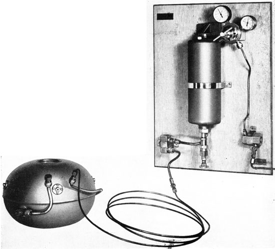
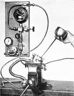
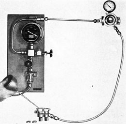
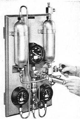
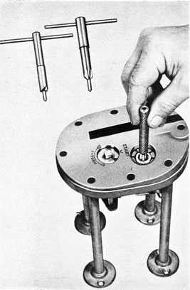
14. Install test set, SG 2855, in drain plug flange. Connect pipe from test panel to test set; crack air line valve and build up pressure in head to 10 p.s.i. Close valve and apply soapy water around all flanges and joints. Bubbles will indicate leaks. Pressure on gage should remain constant for 10 minutes. (Fig. 133B). All leaks must be located and remedied. (191, 141A)
15. After satisfactory test has been made (no leaks), bleed head; remove test set; replace drain plug and washer; remove cover, blanking-off plates, and gaskets; remove blank from air-releasing pipe; and remove water-discharge valve gag (s) and valve (s).
(191, 141A, 13-14, 48, 61, 18)
S. Water-Discharge Valve(s)
1. Inspect and apply grease (E) to leather washer.
2. Inspect spring and renew, if necessary.
3. Clean, inspect, and apply grease (E) to valve guide, seat, and studs in flange.
4. Replace valve, spring, and spring plate, and secure. (48)
145
5. Check action of valve by pushing open with rod several times. Valve should close by spring action alone.
T. Air-Releasing Mechanism Mk 2
*1. Reseat valve seat and lap valve to seat. Renew valve and lap in, if necessary.
(WE24, 200-441)
*2. If necessary to replace guide, unscrew old valve guide, applying heat around threads; screw and solder new valve guide into body; reseat valve seat and lap valve to seat. (WE24, 200-441)
3. When finished lapping, wash parts thoroughly, oil (C), and assemble valve.
4. Check size of hole in restriction nipple. It should be 0.0625 inch (use No. 52 drill).
5. Clean and replace nipple in valve guide and seat against copper washer. (18, 141A)
6. Oil (C) and replace spring support, spring, and adjusting nut.
Note: Before replacing spring, inspect it thoroughly. Renew spring if in doubt about its condition.
7. Connect mechanism to source of high-pressure air (at least 1000 p.s.i.). (141A)
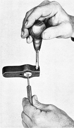
8. Hold valve on seat by pulling out on cocking tool; turn air on and test for leaks by submerging in water with the valve
seated. (200-441)
9. With the above test completed, turn off air pressure and remove air pipe. (141A)
10. Relieve any tension on spring by.
backing off adjusting nut. Replace keep screw. (41)
11. See that 0.020-inch hole in top of adjusting-nut cap is clear.
Note: If this hole is clogged, a small leak by the valve may cause premature blowing of the head.
12. Screw cap in place with washer under seat. (141A)
13. After overhaul, stow air-releasing mechanism, unless it is used immediately.
U. Air-Releasing Mechanism Mk 3
*1. Reseat valve seat and lap valve to seat. Renew valve and lap in, if necessary.
(WE236, 200-441)
*2. If necessary to replace guide, unscrew old valve guide, applying heat around threads; screw and solder new valve guide into body; reseat valve seat; lap guide and valve separately, and lap together. (WE236, WE237, WE238, 200-441)
3. When finished lapping, wash parts thoroughly, oil (C), and assemble valve.
4. Clean and blow out air channels in valve guide with low-pressure air.
5. Oil (C) and assemble valve in guide.
6. Check size of restriction in valve guide. It should be 1/8-inch in diameter.
7. Clean and replace strainer holder with washer in valve guide. (451)
8. Clean and replace strainer in strainer holder.
9. Check size of hole in restriction nipple. it should be about 3/16-inch in diameter.
10. Clean and replace nipple in strainer holder, and seat against copper washer. (451, 229)
11. Oil (C) and replace spring support, spring, and adjusting nut.
Note: Before replacing spring, inspect it thoroughly. Renew spring if in doubt about its condition.
12. Connect mechanism to source of high-pressure air (at least 1000 p.s.i.). (141A)
13. Turn on air and test for leaks by submerging in water.
14. With the above test completed, turn off air pressure and remove air pipe.141A)
15. Relieve any tension on spring by backing off adjusting nut. Replace keep screw. (41)
16. See that 0.020-inch hole in top of adjusting nut cap is clear, and screw cap in place with washer under seat. (141A)
Note: If this hole is clogged, a small leak by the valve may cause premature blowing of the head.
17. After overhaul, stow air-releasing mechanism, unless it is to be used immediately.
V. Headlight Mechanism
1. Thoroughly clean and inspect all parts. Make certain that all contact
146
surfaces are clean and smooth. Make certain that all insulators are free from cracks.
*2. Assemble headlight mechanism:
(a) Replace upper contacts and springs on phenolic top and secure with pins. Peen ends of pins. Solder wires to contacts.
(b) Replace phenolic top assembly on central support rod over insulator.
(c) Replace bottom plate assembly:
(1) Replace insulator and phenolic bottom on bottom plate.
(2) Thread wires through conduits.
(3) Replace bottom plate assembly and conduits. Secure bottom plate assembly to central support rod with key and nut. Drop solder on bottom end of nut, around threads, to prevent nut from turning. (141A)
(4) Solder wires to bottom contacts.
(d) Assemble parts on base plate:
(1) Replace insulator for bulb contact, lining up holes for screws.
(2) Replace bulb contact and secure with screws. (41)
(3) Replace bulb socket and secure with screws. (41)
(4) Solder wire to bulb socket.
(5) Replace switch lever and spring. Secure lever with washers and cotter pin. Replace wire and connection on lever, and secure with nut. (92, 435)
Note: Make certain that contact screw in switch lever is adjusted properly.
(6) Replace inertia weight and spring, and secure with washer and cotter pin. (92)
(e) Replace reflector, holding clips, screws, and nuts in headlight body. (41)
Note: Do not tighten screws at this point. Reflector must be focused. (See step 5, below.)
(f) Replace headlight body on base plate, holding base plate with spanner wrench. (499)
*3. Screw in bulb. See Note under step
I, 2.
4. Replace batteries.
Note: In the case of new batteries, it may
be necessary to fit batteries between contacts.
*5 Focus reflector:
(a) Place headlight assembly on table; trip inertia weight and adjust reflector until headlight throws a three-foot-diameter circle on ceiling six to eight feet above table. Open switch.
(b) After adjustment, tighten screws for holding clips. (41)
6. Screw headlight assembly into casing. Note that good washer is in place.
7. Replace washers and lens. Replace retainer rings and secure with holding screws. (41)
W. Marker-Bomb Switch
1. Remove two nuts securing plunger assembly to switch block. (48)
2. Remove plunger assembly.
3. Check plunger to see that the striker is tight and that knurled end and silver contact are clean and free of verdigris.
4. Note that silver contact and contact spring on switch block are clean and free of verdigris.
5. Check switch leads and terminal screws. Leads should be in good condition and terminal screws tight, with no corrosion present. (41)
6. Replace plunger assembly and note that bend in contact spring is such that it does not interfere with movement of plunger but still makes a good sliding contact with the knurled end of the plunger.
7. Secure the plunger assembly to studs in switch block with two nuts. (48)
8. Stow switch in a safe dry place until ready for use.
X. Battery Assembly
1. Remove two screws, spacer tubes, and nuts securing top plate to base plate. (41)
2. Remove batteries from casing and test with ammeter. Each battery should deliver at least one ampere for sure firing of marker-bomb cartridge.
3. Inspect all contacts and terminals for
tightness and freedom from corrosion.
4. Note that battery casing lugs do not touch battery contacts on base plate. Also
147
note that no corrosion or salt water residue which might cause grounding of the battery contacts is present on the base plate.
5. Replace batteries in casing (one cell right-side-up and the other inverted) and secure with top plate, spacer tubes, screws, and nuts. (41)
Note: If marker-bomb head is not to be used in the immediate future, it is well to leave the batteries out of the casing until time for use.
6. Test battery assembly with ammeter across terminals. Batteries should deliver at least one ampere. If less than one ampere is delivered, check for weak cells or poor contacts.
7. Stow battery assembly with switch assembly until ready for use.
Y. Marker Bomb
1. Remove used cartridge. Remove clamping nut and remove remains of lead sealing disc. (186)
2. Clean interior and exterior of marker-bomb body, with particular attention to beveled seat for flange.
3. Apply a light coating of grease (E) to interior and exterior surfaces of marker-bomb body to prevent corrosion if not to be used immediately.
4. Replace clamping nut, but do not set up tight.
5. Stow marker-bomb with switch and battery assembly.
Exercise head is now ready for final test and installation on air flask. (See Chapter 7.)
Chapter 8-Section 2
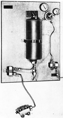
AIR-FLASK SECTION
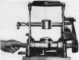
A. Disconnect and Remove Afterbody from Air Flask
1. Blow down flask through flask blow valve. (49)
2. Disconnect the following pipes:
(a) Main air connection from reducer to stop and charging valve. (134)
(b) Pipe from reducer to air checks. (229)
(c) Pipes to fuel and water checks from restriction valve. (144, 229)
(a) Remove holding screws and guide block. (41, 74)
(b) Insert Tool 419 in speed-change upper operating shaft and turn to "between speed" position. (419)
(c) Screw in lifting screw and lift out upper shaft. (74)
4. Screw lifting screws in afterbody
handhole covers; install sling around afterbody and take the weight with chain fall. (200-441)
5. Remove joint screws and afterbody.
(455)
Note: When the afterbody is in position, the pipe from the combustion flask to the nozzle lies behind the holding screw bosses of the joint ring and the afterbody cannot be withdrawn by a straight pull aft. Standing at the tail facing forward, swing the afterbody to the right until this pipe clears the joint ring bosses. Failure to observe this precaution will result in badly scored pipe and may loosen the bosses.
6. Place afterbody on stand.
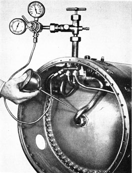
B. Test Prior to Disassembly
1. Charge air flask to 800 p.s.i. and test for leaks around the forward bulkhead. Squirt light lubricating oil (C) around the bulkhead joint and note if bubbles appear.
2. Test air-flask blow valve for leaks, using oil (C). (49)
3. In welded air flasks, note if air-vent plug and bushing leak, using oil (C).
4. In welded air flasks, note if air-outlet elbow in forward dome leaks, using oil (C). 5. With main air nipple blanked off,
148
operate stop valve to open and close, and note leaks. (227-227A)
6. Note if charging check valve leaks. (13-14)
7. Open air-flask blow valve and bleed air from air flask until empty. (49)
DISASSEMBLE AIR FLASK
C. Remove Air-Check-Valve Assembly
1. Remove pipes from check valve to water compartment bulkhead. (229)
2. Remove pipe to vent fitting. (141A) 3. Remove holding screws and check valve assembly. (41)
D. Remove Fuel and Water Check Valve and Strainer Assembly
1. Remove pipe from water compartment bulkhead to fuel strainer. (144)
2. Remove pipe from water compartment
bulkhead to water strainer. (229)
3. Remove pipe to vent fitting. (141A)
4. Remove holding screws and check valve and strainer assembly. (41)
E. Remove Stop and Charging Valve
1. Disconnect main air pipe at water compartment bulkhead. (134)
2. Remove holding screws and stop and charging valve. (41)
F. Remove Vent Fitting
1. Remove holding screws and vent fitting. (41)
G. Remove Water Compartment Bulkhead Assembly
1. Remove water and fuel filling plugs. (11, 74, 217)
2. Unscrew clamp nut for main air connection through water compartment bulkhead. (241A-242A)
3. Back off on lock nuts on water-compartment air-inlet and water-outlet clamping nipples. (144)
6. Insert lifting handles and remove water-compartment bulkhead assembly.
Note: It may be necessary to tap around joint with lead hammer to loosen white lead.
H. Remove Forward Air-Flask Bulkhead-Forged Flask
1. Remove pipe from blow valve body to exercise head. (404)
2. Disconnect pipe from air flask to blow valve at blow valve. (404)
3. Remove holding screw and blow valve. (41)
4. Insert eye bolt in threaded holes in bulkhead. (234)
5. Remove bulkhead holding screws. (135A)
6. Push bulkhead clear of seat; rotate bulkhead, and, with flats lining up with slots in seat of flask, slide head out clear.
Note: It is extremely important to protect the bulkhead and flange seats from the slightest damage during overhaul.
I. Remove Forward Air-Flask Bulkhead-Welded Flask
1. Loosen clamp nut; remove locating clamp; and replace clamp nut on stud in forward bulkhead. (150)
2. Attach piece of wire or heavy string to clamp bolt under clamp nut and holding string (or wire) in one hand, to prevent forward bulkhead from falling inside air flask; push forward bulkhead aft to break seat.
3. Turn flats in bulkhead to line up with slots in air-flask forward dome, and remove forward bulkhead.
J. Remove Flask Blow Valve-Welded Flask
1. Disconnect pipe from air flask to blow valve at blow valve. (404)
2. Remove pipe to exercise head. (404) 3. Remove holding screw and blow valve from flask. (41)
*K. Remove Pipe from Air Flask to Blow Valve-Forged Flask
1. Straighten bend in pipe sufficiently to unscrew.
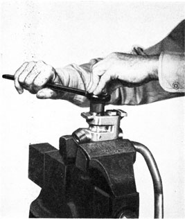
2. Saturate a rag with water and pack on forward flask head seat in wake of pipe. Apply sufficient heat around threads to run solder and unscrew pipe. (Excessive heat may warp bulkhead seat out of line and cause a leak.) (314)
149
*L. Remove Pipe from Air Flask to Blow Valve-Welded Flask
1. Unscrew nut from air-outlet elbow in forward dome and remove pipe. (404)
*M. Remove Air-Outlet Elbow in Forward Dome-Welded Flask
1. Apply heat and clean off solder around outside of elbow.
2. Apply heat to soften solder on elbow threads, and unscrew elbow.
*N. Remove Main Air Connection from After Bulkhead
1. Back off clamp nut and remove main air pipe assembly through forward end of flask. (241A-242A)
Note: In the case of a welded air flask, a long hardwood stick may be used for this purpose.
*O. Remove Air Vent Bushing and Plug-Welded Flask
1. Remove keep screw. (37)
2. Remove bushing and plug. (8-9)
3. Unscrew plug from bushing. (400-B)
The above completes the disassembly of the Air-Flask Section.
OVERHAUL, ASSEMBLY
AND TESTS
P. Treat Interior of Air Flask-Forged Flask
1. Clean thoroughly of oil and examine for corrosion. If corrosion or discoloration is noted, the surface must be scrubbed with a suitable grease solvent, using a stiff bristle brush, and thoroughly dried. Use of alkalies, gasoline (or other volatile liquids) for cleaning is forbidden. When flask is thoroughly dry, give all electroplated surfaces a light coating of preservative (J).
Q. Treat Interior of Air Flask-Welded Flask
1. Clean interior thoroughly with hot water by swabbing with stick and rag. Blow flask dry.
Note: No preservative should be applied to interior of welded flask.
*R. Replace Main Air Connection on After Bulkhead
1. Apply a thin coat of a mixture of 75 per cent pure strained white lead and 25 per cent light lubricating oil (C) to lapped surface of nipple and after head.
2. Insert main air connection in bulkhead through forward end.
Note: In the case of a welded air flask, a long hardwood stick may be used for this purpose.
3. Slip clamp nut in place over after end of pipe and secure. (241A-242A)
S. Replace Forward Bulkhead-Forged Flask
*1. Apply carborundum grinding compound mixed with oil (C) sparingly around seat on bulkhead.
*2. Insert bulkhead through slots in air-flask seat and pull bulkhead up to its seat in flask, catching one holding screw to hold in place until ready to grind. (135A)
*3. Install a bar through the eye bolts and loop a piece of 21-thread manila rope around this bar and the back of the operator to obtain pressure on seat, and proceed to grind bulkhead to its seat, wiping and inspecting occasionally until a good seat is obtained all around.
*4. Remove rope and bar.
5. Clean and dry ground seats thoroughly with a suitable grease solvent (do not use lye or other alkali, gasoline, or volatile oils) and apply a mixture of 75 per cent pure strained white lead and 25 per cent light lubricating oil (C) to both seats.
6. Insert bulkhead through slots in air-flask seat and pull bulkhead up on its seat with numbers stamped uppermost; line up to holes and proceed to secure with ten holding screws coated with oil (D). (It is sometimes necessary to run a 5/16 inch x 24 die over the holding screws to secure a
proper fit.) (135A)
7. Remove eye bolts. (234)
*T. Replace Air-Outlet Elbow in Forward Dome-Welded Flask
1. Remove baked coating (Heresite) around tapped hole for elbow.
150
2. Thoroughly clean threads on elbow and in tapped hole, using tap and die. (5/16-18NC-2)
3. Tin threads on elbow and in tapped hole.
Note: When tinning threads in tapped hole, take care not to plug hole in dome or let solder run into air flask.
4. Heat elbow and tapped hole until
Figure 134A
solder is just fluid, and screw elbow into tapped hole.
5. When elbow is in place, run a small fillet of solder around joint.
6. Touch up, with air-drying Heresite, the area on forward dome which was cleaned for soldering.
Note: If elbow leaks after it has been replaced as outlined above, proceed as follows:
7. Remove elbow and clean parts.
8. Run die over threads on elbow to increase length of threads and enable bottom of elbow to seat in dome. Replace. elbow.
9. If elbow, when seated, does not line up with pipe to air flask blow valve, remove elbow, dress off bottom of elbow, and replace.
U. Replace Forward Bulkhead-
Welded Flask
*1. Apply carborundum grinding compound mixed with oil (C) sparingly around seat on bulkhead.
*2. Insert bulkhead through slots in air-flask seat and pull bulkhead up to its seat, using wire or heavy string.
*3. Install grinding tool and proceed to
Figure 134B
grind bulkhead to its seat, wiping and inspecting occasionally until a good seat is obtained all around.
Note: Grinding tool should be made by activity performing this operation.
*4. Remove grinding tool.
5. Clean and dry ground seats thoroughly with a suitable grease solvent (do not use lye or other alkali, gasoline, or volatile oils) and apply a mixture of 75 per cent pure strained white lead and 25 per cent light lubricating oil (C) to both seats.
6. Secure wire to clamp bolt in bulkhead and insert bulkhead through slots into flask (Fig. 134A).
7. Rotate bulkhead about 90 degrees so flats are not in alignment with slots in
151
seat, and pull up to seat with wire (Fig. 134B).
8. Replace locating clamp, making sure that it seats in channel in bulkhead and slots in bulkhead seat.
9. Assemble clamp nut with shoulder of nut outboard. (150)
*V. Replace Pipe from Air Flask to Blow Valve-Forged Flask
1. Clean tapped hole in flask bulkhead flange with 5/16-inch-20 bottoming tap.
2. Tin threaded end of pipe and tapped hole.
3. Apply enough heat on flange to run solder, and screw pipe in place. (314)
4. After resoldering, see that hole in pipe is clear of solder.
*W. Replace Pipe from Air Flask to Flow Valve-Welded Flask
1. Replace pipe; bend to shape if necessary; and secure to air-outlet elbow in forward dome. (404)
X. Flask Blow Valve
1. Disassemble valve by removing set screw, retainer, washer, and valve. (37, 155)
2. Clean and inspect blow valve body and parts. Remove burrs, where necessary, on nipples and in blow valve seat. Apply oil
(C) to valve.
3. Replace new washer around blow-valve stem and assemble blow valve in body. (49)
4. Replace retainer over blow-valve stem and secure with set screw. (155, 37)
5. Replace blow valve on air flask and secure with screw. (-11)
6. Connect pipe from air flask to blow valve. (404)
*Y. Air-Vent Bushing and Plug-Welded Flask
1. Wash all parts thoroughly.
2. Examine threads on bushing (screw to "open" position). (400B)
3. Replace plug and bushing assembly and secure with keep screw. (400B, 8-9, 37)
4. Tighten down plug. (400B)
Figure 135
152
Figure 136
Z. Water-Compartment Bulkhead Assembly
1. Disconnect from bulkhead, air pipe to fuel flask and fuel pipe from fuel flask. (229, 144)
2. Remove screws securing fuel flask to bracket, and remove fuel flask. (49 or 49A)
*3. Remove pipes from fuel flask. (229, 144)
*4. Clean, inspect, dress off burrs where necessary, and replace pipes on fuel flask. (WE 94, WE94A, 229, 144)
*5. Remove pipes from bulkhead seat flange in water compartment. (229)
*6. To remove nipples in bulkhead or bulkhead-seat flange, apply only sufficient heat to each nipple to run solder and unscrew nuts and nipples. (144, 229)
*7. To replace nipples, clean tapped holes in bulkhead or bulkhead seat flange; tin threads on nipples; screw into holes; and secure with nuts. Apply only sufficient heat to keep solder soft until screwed all the way up. After soldering in place, reseat seats on ends of nipples and chase burrs off threads. (144, 229, WE94, WE94A)
*8. Clean, inspect, dress off burrs where necessary, and replace pipes on nipples in
bulkhead-seat flange in water compartment. (229)
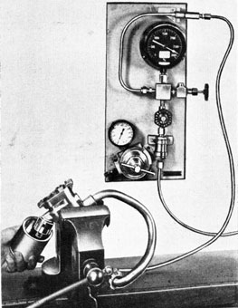
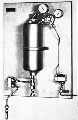
9. Test fuel flask for leaks (Fig. 135).
(a) Replace fuel-filling plug. (217)
(b) Blank off air-inlet pipe. (229)
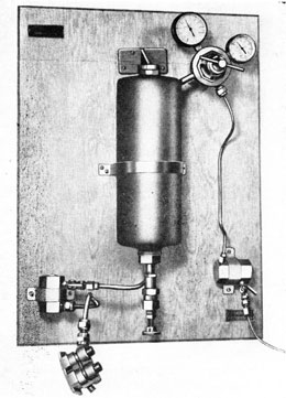
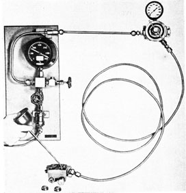
(c) Connect a test pipe from fuel-outlet connection to outlet-valve cock for Spray, Check Valve, and Fuel Flask Testing Outfit (described in OP 1217). The test pipe must be of sufficient length to permit submerging the fuel flask in water. No water should be used in test tank of testing outfit when testing fuel flask. (141A, 144)
(d) Open low-pressure air valve and adjust reducing valve to 25 p.s.i. Open outlet valve cock and admit this pressure into fuel flask.
(e) Submerge fuel flask in water and note if bubbles rise, indicating a leak.
(f) Test completed, disconnect test pipe; remove blank from air connection; dry fuel flask; and cover with light lubricating oil (C). (141A, 144, 229)
(g) Remove fuel-filling plug. (217)
Figure 137
153
10. Replace fuel flask on brackets and secure with screws. (49 or 49A)
11. Connect pipes on fuel flask to water compartment bulkhead. (144, 229)
12. Clean bulkhead and flange seats, including tapped screw holes, and apply a mixture of 75 per cent pure strained white lead and 25 per cent oil (C) to seats.
13. Clean interior of water compartment and apply a light coat of preservative (J).
14. Install water-compartment bulkhead assembly, guiding main air-connection nipple through hole in bulkhead, and secure with holding screws dipped in oil (D). (12)
15. Replace clamping nipples and lock nuts for pipe from air checks to water space and pipe from water space to water strainer. (1-14)
16. Screw clamp nut over main air-connection nipple and secure. (241A-242A)
AA. Vent Fitting
1. Inspect threads of nipples for burrs; blow out channels with low-pressure air and assemble to shell, securing with holding screws. (41)
AB. Stop and Charging Valve
Caution: When clamping valve body in vise, use copper vise jaws and take care not to crush or distort valve body.
1. Remove charging-valve plug and ring seal. (13-14)
Figure 138
Figure 139
2. Remove check valve guide, ring seal, check valve, and spring. (12)
*3. Remove keep screw and bushing for charging valve (Fig. 136). (37, 420, 377)
4. Remove gland nut and ring seal from stop valve plug. (418)
5. Remove stop valve plug, spindle with
follower, and ring seal. (183)
6. Remove stop valve and carrier. (405)
*7. Remove stop valve operating spindle:
(a) Remove set screw from follower.
(37)
154
Figure 140
(b) Remove follower and spindle.
(181-181A)
*8. Scribe assembly marks on main air pipe and stop-valve body. Apply sufficient heat around threads to soften solder; unscrew main air pipe and wipe solder from valve body.
*9. Try threads on main air pipe for fit in threaded hole in valve body; tin threads of both; apply sufficient heat around threads to soften solder and screw pipe in place in body, lining up scribe marks.
Note: If a new pipe is fitted, screw pipe into valve body without soldering. Install valve group on air flask and secure in place. Fit main air pipe to line up with main air nipple in center of water-compartment bulkhead and scribe marks on pipe and stop-valve body; remove and solder in place as described above.
*10. Chase threads in main air-pipe nut and on outlet nipple to reducer (Fig. 137). (WE97, WE98)
*11. Reface seat on main air-pipe collar, and seat on outlet nipple (Fig. 138). (WE81, WE80)
14. Inspect check-valve guide and its seat in valve body for burrs and corrosion.
*15. Reseat check valve-guide seat in valve body (Fig. 139). (WE113)
16. Replace charging check valve, spring, ring seal, and guide. (12)
Note: Before replacing check valve guide, make certain that stop pin in guide is tight.
*17. Screw new charging valve bushing in place; mark place opposite keep screw hole; remove bushing and, with small round file, remove sufficient stock on bushing to correspond with half of hole drilled before tapping. Replace bushing in valve body with hole for keep-screw lining up; run a drill into hole and follow up with a tap. Insert keep screw for bushing.
(420, 377, 37)
*18. Reface stop valve seat. (Fig. 139)
(WE41)
*19. Lap stop valve to seat. Apply lapping compound sparingly; screw stop valve and carrier down to seat, but not hard
Figure 141
155
Figure 142
enough to take up. Insert a screw driver through carrier to slot in stop valve and grind until seated. Wash grinding compound from seat. (405, 41)
Note: This step not necessary in the case of stop valves with nylon insert.
*20. Reface stop valve plug seat (Fig. 139). Wash out chips and blow dry.
(WE42)
21. Clean, inspect, remove burrs, and
lap stop valve spindle to seat in plug. Oil
(C) lightly and assemble spindle, follower, and keep screw in plug (181-181A, 37)
22. Test stop valve plug seat and stop valve spindle seat for leaks:
(a) Clamp valve body in vise.
(b) With stop valve removed, replace (temporarily) ring seal and stop-valve plug assembly in valve body. (183)
(c) Install adapter and blank on outlet nipple on valve body. (134)
Figure 143
(d) Install adapter and connect test lead from main air pipe to General Use Test Panel. (SG-2348)
(e) Crack air-line valve; gradually build up pressure in valve body to 2800 p.s.i. and test for leaks around stop valve plug seat and stop valve spindle seat, using oil (C). Turn off air and bleed line. Do not remove adapters or pipe connections.
(f) Remove stop-valve plug assembly and ring seal. (183)
(g) Remedy leaks if any were found in step (e) above.
23. Clean, oil (C) lightly, and install stop valve carrier with stop valve. (405)
24. Replace ring seal and stop valve plug assembly in valve body. (183)
25. Replace ring seal and gland nut in stop valve plug. (418)
26. Test assembled stop and charging valve:
(a) With adapters and pipe connection still on valve body, close stop valve, turn on air (2800 p.s.i.) and open stop valve slowly. (227-227A)
(b) Squirt oil (C) around charging check valve seat and watch for bubbles (Fig. 140).
156
Figure 144
Figure 145
Figure 146
(c) Close stop valve and remove blank nut from adapter on outlet nipple. (227-227A)
(d) Hold can of water under adapter on outlet nipple. Bubbles will indicate leak past stop valve (Fig. 141).
(e) Close air line valve on test panel and open bleeder valve. Disconnect test lead and remove adapters from stop and charging valve. Remove valve body from vise. (134)
(f) Replace charging valve plug and ring seal. (13-14)
27. Install stop and charging valve on air [ask:
(a) Catch threads in main air pipe nut on nipple on water-compartment bulkhead.
(b) Line up valve body and secure to midship shell with screws.
(c) Fully tighten main air-connection nut. (134)
Figure 147
157
Figure 148
AC. Leakage Test After Assembly
1. Charge air flask to 800 p.s.i. and test for leaks around the forward bulkhead. Squirt oil (C) around the bulkhead joint and note if bubbles appear.
2. Test air-flask blow valve for leaks, using oil (C). (49)
Figure 149
3. In welded air flasks, note if air-vent plug and bushing leak, using oil (C).
4. In welded air flasks, note if air-outlet elbow in forward dome leaks, using oil (C).
Figure 150
With main air nipple blanked off, open and close stop valve and note leaks. (227-227A)
5. Note if charging check valve leaks.
(13-14)
7. Open air-flask blow valve and bleed air from air flask until empty. (49)
Figure 151
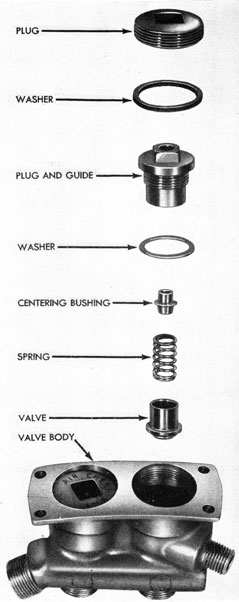
AD. Air Check Valves (Fig. 142)
1. Remove plugs and washers for check-valve body. (405)
2. Remove check-valve plug and guide with centering bushing, check valve, and spring. (12, 74)
*3. Chase threads on nipples (Fig. 143). (WE94, WE95)
*4. Reface seats on nipples (Fig. 144).
(WE83, WE86, 443)
*5. Reseat seats for valves, using air check-valve plug and guide for guiding tool when cutting (Fig. 145). (WE108)
Figure 152
158
Figure 153
6. Reseat seat for air check-valve plug washer (Fig. 145). (WE113)
*7. Reseat bottom seat of valve plug and guide (Fig. 146). (WE111)
*9. Ream out hole in air check-valve plug and guide (Fig. 148). (WE107)
*10. Lap hole in plug and guide (Fig. 149). (WE109)
*11. Lap air check valve (Fig. 150). (WE110, 74)
*12. Lap valve to plug and guide, using oil (C) (Fig. 151). (74)
13. Clean, inspect, oil (C), and assemble air check valves, springs, centering bushings, washers, and valve plugs and guides in air check-valve body, holding valves in plugs with screw rod until threads are engaged. Then remove screw rod and set up on plugs. (74, 12)
14. Replace plugs and washers for check valve body. (405)
15. Test outboard seats of air check valves as follows:
Figure 154
(a) Set up Test Panel (General Use) with reducer and extra length of test pipe (Fig. 152).
(b) Connect test pipe to inlet nipple of air check-valve body. (229)
159
Figure 155
(c) Blank off outlet nipples and vent nipple. (229, 141A)
(d) Remove screw plugs and washers from air check-valve body. (405)
(e) Open inlet valve and adjust reducer to give 350 p.s.i.
(f) Fill check-valve body with oil (C) and check for leaks.
(g) After satisfactory test has been made (no leaks), remove blanking nuts from outlet nipples and vent nipple; replace screw plugs and washers. Disconnect and remove body from test panel.
(141A, 405, 229)
16. Test inboard seats of air check valves as follows (Fig. 153):
(a) Drain bottle of Spray, Check Valve, and Fuel Flask Testing Outfit and blow clean with low-pressure air.
(b) Connect inlet nipple of air check-valve body to outlet pipe of testing outfit. (229)
(c) Open valve cock, admitting low-pressure air (not exceeding 200 p.s.i.) to the reducing valve.
(d) Adjust reducing-valve pressure upward slowly, noting pressure required to lift check valves off their seats. The valves should lift at from 10 to 12 p.s.i.
(e) Disconnect and remove air check-valve body from testing outfit. (229)
17. Remove, wipe dry, oil (C), and replace check valves after test.
(405, 12, 74)
18. Install body on air flask with holding screws, and connect pipes. (41, 229, 141A)
AE. Fuel and Water Delivery Check Valves and Strainers (Fig. 154).
1. Remove plugs and washers for strainers and remove strainers. (405, 372A)
2. Remove plugs and washers for fuel and water check valves. (406)
3. Remove valve guides with valves and springs. (74, 407)
*4. Chase threads on nipples.
(WE94, WE94A, WE95)
Figure 156
160
Figure 157
*5. Reseat nipples.
(WE83, WE85, WE87)
*6. Reface seats for fuel and water check valves in body. (WE123A)
*7. Chase threads in body for valve guides. (WE117)
*8. Mill out holes in body for valve guides. (WE119)
*9. Ream holes in guide for check valve stem. (WE120, WE124)
*10. Reface outer seats of guides for
valves. (WE121)
11. Reface outer seats of valves.
(WE122, WE127)
*12. Reface bevel seats on valves. (WE128, WE128A, WE128B)
*13. Lap valve stems. (WE126)
*14. Lap valve stems to guides. (74)
*15. Lap valves to seats in body.
(407, 74)
16. Clean, inspect, oil (C), and assemble springs and valves in guides and replace in check-valve body. (407, 74)
17. Clean, inspect, and replace check-valve plugs and washers. (406)
18. Clean, inspect, and replace strainers. (Do not set up strainers more than
hand-tight, to prevent sticking on next removal.) (372A)
Note: Check to see that inlet holes to strainers are clear.
19. Replace washers and strainer plugs. (405)
20. Test outboard seats of delivery check valves as follows:
(a) Set up Test Panel (General Use) with reducer and extra length of test pipe (Fig. 155).
(b) Connect test pipe to inlet nipple of fuel-and-water-delivery check valve and strainer body. (141A, 144, 229)
(c) Blank off outlet nipples and vent nipple. (141A, 144, 229)
(d) Remove check valve plugs and washers. (406)
(e) Open air inlet valve and adjust reducer to give 350 p.s.i.
(f) Fill check-valve body with oil (C) and check for leaks.
(g) After satisfactory test has been made (no leaks), remove blanking nuts from outlet nipples and vent nipple; replace check-valve plugs and washers; disconnect and remove body from test panel. (229,144, 144A, 406)
21. Test inboard seats of delivery check valves as follows (Fig. 156):
(a) Drain bottle of Spray, Check Valve, and Fuel Flask Testing Outfit, and blow clean with low-pressure air.
(b) Connect inlet nipple of body to outlet pipe of testing outfit. (144, 229)
(c) Open valve cock, admitting low-pressure air (not exceeding 200 p.s.i.) to the reducing valve.
(d) Adjust reducing-valve pressure upward slowly, noting pressure required to lift check valves off their seats. The valves should lift at from 15 to 20 p.s.i.
(e) Disconnect and remove body from testing outfit. (144, 229)
22. Remove check valves and strainers after test, wipe dry, oil (C) check valves, and replace check valves and strainers.
(74, 405, 406, 407)
23. Install body on air flask with holding screws and connect pipes.
(41, 141A, 144, 229)
161
Chapter 8-Section 3
AFTERBODY-REMOVAL OF MAJOR UNITS FROM
A. Remove Gyro and Depth Mechanism
1. Turn afterbody bottom-up and remove hand-hole plates with gaskets. (200-441, 48)
2. Remove cotter pins, retainer pins, and lock pins for spreaders (for forward gyro index gear assemblies). (72)
3. Swing spreaders and struts clear of and remove forward gyro index gear assemblies.
4. Remove two connecting pins for forks and rudder rods. (449)
5. Disconnect air pipe to depth engine. (14lA)
6. Disconnect air pipe to steering engine.(14lA)
7. Remove air pipe from "T" connection on steering engine to gyro reducing valve. NOTE: When torpedoes have been converted for smokeless running, (NavOrd Ordalt 1654), remove also the airpipe from the "T" connection to the water lubrication check valve. (24)
8. Disconnect valve connections and remove depth and steering engines. (205A-246,49A)
9. Disconnect water pipe from depth-mechanism casing and turn clear. (144)
10. Disconnect gyro spin lead. (437)
11. Remove gyro clamp-plate cover and gasket; lock gyro spinning and unlocking mechanism; replace gyro clamp-plate cover and gasket.(13-14,205A-246)
12. Install transportation pin. (49)
13. Remove holding screws, install lifting screws, and remove gyro and depth mechanism.(456,200-441)
B. Remove Tail
1. Remove after propeller nut-lock screws. (40)
2. Remove after propeller nut (right-hand thread) tapping with lead hammer if necessary. (426)
3. Remove after propeller, tapping close to hub with lead hammer if necessary.
*4. Remove grease shell from after propeller sleeve: Note: This step applies only to those torpedoes which have the improved tail lubricating system installed.
(a) Remove set screw holding grease shell in place. (400)
(b) Insert hooks into two holes in after portion of grease shell and pull shell out of sleeve.
5. Remove nut, after propeller sleeve, and bushings. (183)
6. Remove forward propeller-nut lock screws. (40)
7. Remove forward propeller nut (left' hand thread), tapping with lead hammer if necessary. (425)
8. Remove forward propeller, tapping with lead hammer if necessary.
9. Remove forward propeller hub, and pry out key, noting marks. (41)
10. Remove access hole plugs from tail cone. (13-14)
11. Remove two screws for rudder connecting rod ends. (13-14, or 386)
12. Remove joint screws, and remove tail. (184)
13. Remove wire and locking screws for forward propeller sleeve. (72, 40)
14. Remove forward propeller sleeve.
15. Remove wire, three holding screws, and grease-packing ring from forward propeller sleeve. (72, 41)
C. Disassemble Parts on Turbine Bulkhead
Disconnect and remove parts attached to the turbine bulkhead in the following order:
1. Water pipe to restriction valve. (229)
2. Fuel pipe to restriction valve. (144)
3. Vent pipe to bulkhead. (141A)
4. Water pipe, midship section to bulkhead. (141A, 457)
5. Air pipe from reducing valve (to air check valves). (229)
6. Air pipe, reducing valve to igniter. (141A)
7. Air pipe, bulkhead to reducing valve (return from starting gear). (141A)
8. Air pipe, reducing valve to bulkhead (control valve). (141A)
162
Figure 158
9. Air pipe, starting valve to bulkhead (starting gear). (141A)
10. Air pipe, starting valve to bulkhead (gyro spin). (229)
11. Air pipe, combustion flask to bulkhead (strainer body). (141A)
12. Water pipe, restriction valve to sprays. (229, 144)
13. Fuel pipe, restriction valve to spray. (144)
14. Air pipe, reducing valve to combustion flask. (134)
15. Main air pipe to bulkhead (to pre-heater). (134)
16. Main air pipe, bulkhead to starting valve (preheater). (134)
17. Wire, screws, and reducing-valve body assembly. (72, 13-14, or 386)
18. Four screws for speed-change operating shaft bracket (not applicable to Mk 23 type). (40)
19. Roller pivot screw and roller for valve rack (not applicable to Mk 23 Type). (41)
20. Screws for speed-change bracket, and speed-change bracket with parts assembled (not applicable to Mk 23 Type).
(386)
21. Four holding screws for nozzle-valve bonnet, bonnet with valve, stem and rack and gasket (not applicable to Mk 23 Type).
(459)
22. Nuts and screw, and nozzle unit with combustion flask assembly. (227-227A, 435)
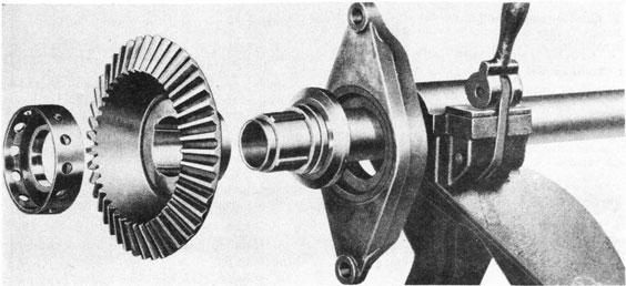
D. Disconnect and Remove Main Engine from Afterbody
1. Remove nuts, manifold cover, and gasket. (48, 200-441)
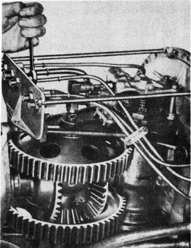
2. Remove pipes connected to forward nipples on manifold (Fig. 158):
(a) Starting gear. (14lA)
(b) Air strainer. (14lA)
(c) Oil pump. NOTE: When torpedoes have been converted for smokeless running (NavOrd Ordalt 1654), this connection will be from the manifold to the water lubrication check valve.
(d) Control valve. (141A)
(e) Gyro spin. (229)
(f) Starting-gear return (141A)
3. Remove nuts from turbine bulkhead. (457)
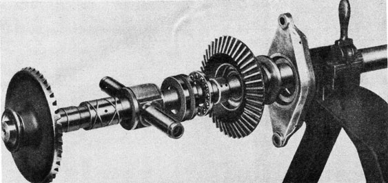
4. Remove main engine from afterbody:
(a) Screw guide tool on end of after propeller shaft.
(b) Install lifting handles on preheater pipe nipple and gyro-spin pipe nipple on bulkhead.
(446)
Figure 159
163
(c) Remove pin and roller from supporting bracket (SG 3174), insert bracket through gyro door, and replace roller and pin under shaft.
(d) Secure guide bracket (SG 2879) to lower forward end of afterbody.
(e) With one man on each lifting handle and one man supporting shafts, pull main engine out of afterbody about four inches.
(f) Disconnect water pipe from nipple on after side of turbine bulkhead (Fig. 159). (141A)
(g) Remove main engine from after-body and clamp in overhauling stand.
Note: In order to remove control valve from afterbody when the latter is assembled, it is necessary to remove forward gyro index gear assembly (see steps A-2 and A-3, above).
1. Disconnect air pipe from control valve to air-strainer body. (141A)
2. Disconnect air pipe from manifold to control valve; steady control valve with wrench. (402, 141A)
3. Loosen screw in control valve clamp and remove control valve. (41)
F. Remove Starting Gear
1. Disconnect pipes from starting gear. (141A)
2. Remove holding screws and lift out starting gear and gasket. (41)
Chapter 8-Section 4
AFTERBODY-WITH PARTS ASSEMBLED TO SHELL
A. Remove Gyro Index Setting Device
(See steps A-2 and A-3 of Section 3 for removal of spreaders and forward gyro index gear assemblies.)
1. Remove cotter pins and index-gear struts. (72)
2. Remove nuts from angle-setting sockets. (227-227A, 141A)
3. Remove after gyro index gears from angle-setting sockets. (It may be necessary to pry them off with a screw driver.)
(227-227A)
4. Remove spreaders from angle-setting socket bearings.
5. Remove setting sockets, ring seals, and spacers. (227-227A)
B. Remove Rudder Rods and Connections
1. Remove split taper pins securing rudder connection forks to rudder connections passing through packing glands in after bulkhead. Remove forks. (72, 166)
2. Loosen packing-gland nuts and remove rudder rods, pulling rudder connections through packing glands from inside.
(229)
C. Remove Exhaust Valves
1. Remove cotter pins and nuts for exhaust-valve bracket. (72, 408)
2. Remove exhaust-valve bracket springs, and valves.
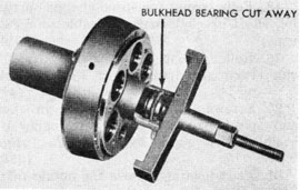
D. Remove After Bulkhead Bearing
1. Remove screws for after bulkhead bearing. (227-227A)
2. Remove U-seal retainer and U-seal.
3. Remove after bulkhead bearing, using puller (SG 2858) (Fig. 160). (191)
4. Remove washer for bulkhead bearing.
Figure 160
164
E. Remove Pipes From Afterbody
1. Water pipe, bulkhead to depth mechanism casing (pull pipe aft and slip it through pipe tie).
2. Manifold to air-strainer body. (141A)
3. Air-strainer body to depth engine. (141A)
4. Air-strainer body to steering engine. (141A)
5. Control valve to air-strainer body. (141A)
6. Manifold to starting gear. (141A)
7. Starting gear to manifold. (141A)
8. Manifold to control valve. (141A)
9. Manifold to gyro spin nipple. (229)
*F. Remove Oil Tanks
1. Drain tanks and remove filling pipes.
(13-14, 451)
2. Remove cotter pin, nut, and clamp for
vent pipes. (72, 155)
3. Remove vent pipes. (438,`:
4. Remove oil suction pipe from manifold to oil tanks (both ends). (183, 229)
5. Remove wire and holding screws for oil tanks. (72, 40)
6. Remove oil tanks and spacing washers from afterbody.
*G. Remove Horizontal Bulkheads
1. Remove wire, screws, and horizontal bulkheads. (72, 41)
*H. Remove Exhaust Tubes
1. Remove wires through screw heads, and remove screws and thimbles for exhaust tubes. (72. 41)
2. With a screw driller, pry under edges of after end of exhaust tubes, bending tubes in sufficiently to clear rolled projection from grooves in tube holes in afterbody bulkhead.
3. Pull tubes clear of after bulkhead and remove.
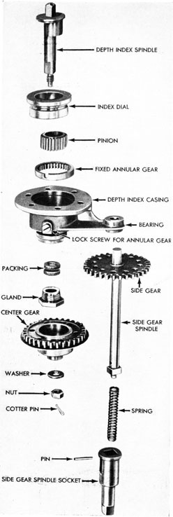
I. Remove Depth-Setting Mechanism
1. Remove cotter pin, nut, and washer from depth-index spindle. (72, 155)
2. Remove center gear.
3. Remove side-gear spindle assembly.
4. Loosen packing gland nut and push out index spindle. (18)
5. Remove index dial and pinion.
6. Remove gland nut and packing.
*7. To remove fixed annular gear, apply sufficient heat on lock screw to soften solder. Remove lock screw and pry out fixed annular gear. (41)
Note 1: Fixed annular gear should not be removed unless replacement is required.
Note 2: When removing lock screw, take care to apply only enough heat to soften solder holding set screw. Too much heat may melt solder around depth index casing, causing a leak.
8. Remove pin, socket, and spring from side-gear spindle. (166)
OVERHAUL, ASSEMBLE, AND TEST
PARTS ASSEMBLED TO
AFTERBODY SHELL
J. Afterbody Shell
1. Clean and inspect afterbody shell for dents, loose rivets, and loose solder around bulkheads, rings, flanges, etc. NOTE: When torpedoes have been converted for smokeless running, (NavOrd Ordalt 1654), under no circumstances should any oil be allowed to remain on any of the surfaces of the afterbody, the exhaust tubes, or the vertical and horizontal bulkheads. If the afterbody tinning is deficient, a coating of rust-preventive (K) may be applied without affecting the smokeless running qualities if (K) is kept from the vertical and horizontal bulkheads, the inside and outside of the exhaust tubes, and that portion of the afterbody shell between the turbine bulkhead and the vertical bulkhead.
Figure 161
165
Figure 162
*K. Exhaust Tubes
1. Reform and insert exhaust tubes through forward end; guide ends into holes in after bulkhead; push into place; and line up forward ends with holes in vertical bulkhead.
2. Insert thimbles for exhaust tubes and secure with screws. Wire screws together.
(41, 72)
3. Roll exhaust tubes into grooves in after bulkhead (Fig. 161). (39, WE208)
L. After-Bulkhead Bearing
1. Clean bearing and inspect bearing surfaces and seats for burrs and scoring.
2. Apply light coat of grease (E) to bearing.
3. Insert washer for bearing in bulkhead.
4. Install bearing in bulkhead, using assembly tool (SG 2849) (Fig. 162).
(191, 227-227A)
5. Install U-seal and retainer and secure with screws. (227-227A)
*M. Horizontal Bulkhead
1. Clean, inspect, and straighten bulkheads if necessary.
2. Install bulkheads in afterbody and secure with screws. Wire screw heads.
(41, 72)
N. Nipples in Afterbody
1. Clean, inspect, reseat, and chase threads where necessary.
(WE83, WE85, WE94, WE95)
O. Afterbody Pipes
1. Make certain that there are no obstructions in pipes.
*2. Anneal pipes.
*3. Reface pipe collars and chase threads in pipe nuts with taps. (WE84. WE86)
P. Screws in Flanges
1. Clean and inspect screws in flanges for hand-hole plates, manifold cover, and turbine bulkhead for looseness or defects.
2. Chase threads, resolder, or replace screws where necessary. (490. WE23)
*Q. Oil Tanks
1. Clean and inspect oil tanks.
2. Wash out interior of tanks with grease solvent and blow dry with air. Note that ball check valves are free by shaking tanks.
3. Reseat nipples and chase threads where necessary.
(WE83, WE85, WE94, WE95. WE102)
4. Reface pipe collars. (WE84. WE86)
5. Install oil tanks and spacing washers and secure with screws. Wire screw heads. (40, 72)
6. Install and connect oil-tank vent pipes; secure with clamp, nut, and cotter pin. (438, 155, 72)
7. Install oil-tank filling pipes and connect to tanks and filling flange. (451)
8. Install oil suction pipe; connect to tanks and to manifold. (229, 183)
R. Depth-Setting Mechanism (Fig. 163)
*1. If removed, install fixed annular gear with recess in line with lock screw hole.
*2. Tin lock screw, apply heat, and screw in place (see Note 2 under step 1-7). (41)
3. Clean, inspect, oil (C), and assemble
166
Figure 163
spring and socket on side-gear spindle. Secure with pin. (166)
4. Clean, inspect, and oil (C) depth-index spindle, dial, and pinion.
5. Insert depth-index spindle through dial, and slip pinion over eccentric on spindle.
6. Insert spindle, dial, and pinion assembly in depth-index casing, turning until in mesh with annular gear. (135A)
7. Renew packing, soaked in oil (D); replace and tighten packing-gland nut. (18)
8. Install side-gear spindle assembly in bearing in casing; hold in place and install center gear.
9. Secure center-gear to spindle with washer, nut, and cotter pin. (155, 72)
S. Rudder Rods and Connections
1. Clean, inspect, oil (C), and insert rudder rods and connections through packing glands in after bulkhead.
Figure 164
2. Repack packing glands, using approximately nine inches of 3/16-inch-diameter asbestos packing. Set up on gland nuts gradually, while working rudder rods back and forth. Use oil (D) while working in packing. When properly packed, rudder rods should move with a force of nine pounds or less, with the gland nut set up flush (Fig. 164). (229, 98)
Note: Gland nuts should come up against glands in order to allow full travel of rudder rods. If gland nuts protrude, it will be necessary to reduce the amount of packing in the gland.
3. Replace rudder connection ends; line up taper pin holes properly; and drive split taper pins into place. Spread ends of pins.
(166, 72)
167
T. Exhaust Valves
1. Clean and inspect exhaust valves and their seats on the afterbody bulkhead. Remove ring seals from valves.
2. Apply spotting fluid to valve seats on afterbody bulkhead; insert valves in exhaust holes; and rotate valves back and forth, using screw driver in valve stem slot. Remove valves and note amount of contact between valves and seats, as indicated by the spotting fluid. (41)
3. If valve seats on bulkhead are not true, grind valves to seats, using light grinding compound. After grinding, wash off compound from valves and seats. (41)
4. After grinding, lap valves to valve seats, using oil (C). After lapping, wipe parts clean. (41)
5. Slip new ring seals on valves; insert valves in exhaust holes and assemble springs on valves.
6. Replace valve bracket and secure with holding nuts and cotter pins. (408, 72)
NOTE: If Torpedo is To Be Used In Exer. Firing, Do Not Install Ring Seal.
U. Gyro Index-Setting Device
1. Clean angle-setting socket bearings
paying particular attention to seats for ring seals and spacers.
2. Clean; inspect threads for burrs; place ring seals and spacers on sockets.
3. Oil (C) sockets and replace in angle-setting socket bearings. (227-227A)
4. Clean, inspect for alignment, oil (C), and replace spreaders on angle-setting socket bearings.
5. Clean and inspect after gyro index gears. Place gears on surface plate and check for alignment.
6. Replace gears on index-setting sockets and secure with holding nuts.
(227-227A, 141A)
Note: When securing gears, tighten holding nuts until sockets bind up solidly. Back off nuts just enough to allow sockets to turn with a slight drag. In this position, ring seals are compressed, but there is 0.001 to 0.002 inch clearance between spacers and bearings.
7. Clean, inspect, oil (C), and replace index gear struts. Secure with cotter pins.
(72)
Note: Forward gyro index-gear assemblies should not be installed until after installation of gyro mechanism. See Section 10.
V. Secure Rudder Rods
1. Wire free ends of rudder rods to after gyro index gears (to prevent interference while installing gyro mechanism).
W. Replace Pipes in Afterbody
1. Manifold to air-strainer body. (141A)
2. Air-strainer body to depth engine. (141A)
3. Air-strainer body to steering engine.
(141A)
4. Control valve to air-strainer body. (141A)
5. Manifold to starting gear. (141A)
6. Starting gear to manifold. (141A)
7. Manifold to control valve. (141A)
8. Manifold to gyro-spin nipple. (229)
9. Water pipe, bulkhead to depth-mechanism casing (slip small nut through pipe tie).
Note: Small nut on pipe must be forward.
The above completes the assembly of the afterbody shell prior to installation of major units.
168
Chapter 8-Section 5
VALVE GROUP AND SUPERHEATER
DISASSEMBLY
A. Disassemble Valve-Group Body Assembly
1. Reducing valve:
(a) Secure valve-group body assembly to swivel stand. (386)
(b) Remove follower nut and reducing valve nipple connection. (377)
(c) Remove lock screw and washer for packing gland. (389)
(d) Remove packing gland and packing for reducing valve stem. (422, 482)
(e) Remove reducing-valve stop plug and washer. (13-14)
(f) Remove cotter pin and lock nut for reducing valve. (421, 227-227A, 72)
(g) Remove reducing valve.
(421, 227-227A)
(h) Push out reducing-valve stem.
(i) Remove control pipe from body.
(141A)
2. Starting valve:
(a) Remove follower and starting-valve nipple connection. (420, 377)
(b) Remove spring and push out starting valve. (74)
3. Restriction valve (not applicable to Mk 23 Type):
(a) Loosen gland and unscrew restriction-valve stuffing box. (434, 377)
(b) Remove plug and washer for restriction-valve body. (427)
(c) Place pin wrench on pinion and pull restriction valve out of body, turning the valve when pulling out of body. (439)
(d) Remove taper pin and pinion. (166, 467)
(e) Remove stuffing box and gland.
(f) Remove gland and packing from stuffing box. (434, 377, 482)
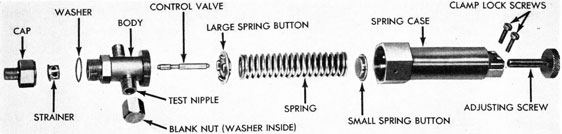
B. Disassemble Control Valve
1. Remove cap and washer for control valve-body. (402)
2. Remove strainer.
3. Clamp spring case in vise (being careful not to distort it) and unscrew control-valve body with valve. (402)
Figure 165
169
4. Remove control valve.
5. Remove blank nut and washer for test nipple. (18)
6. Remove large spring button, spring, and small spring button.
7. Loosen clamp screws and remove control-valve adjusting screw. (40)
C. Disassemble Combustion Flask and Nozzle Unit
1. Remove fuel spray and washer. (51A, 406)
2. Remove water sprays and washers. (51A, 406)
3. Remove dummy igniter and washer. (391A)
4. Disassemble sprays:
(a) Remove spray body and washer from spray holder. (12)
(b) Remove plug and whirl from spray body. (41)
*5. Remove plugs and washers from nozzle holes. (466)
*6. Remove test plug and washer from
nozzle hole. (183)
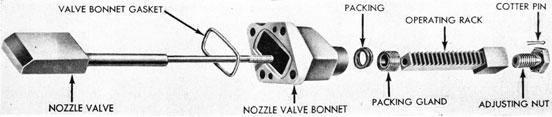
*7. Disassemble nozzle valve and bonnet
assembly (not applicable to Mk 23 Type): Note: For removal of this assembly from
nozzle unit, see Section 3.
(a) Unscrew operating rack, with adjusting nut, from valve stem.
(b) Loosen packing gland and remove nozzle valve from bonnet. (440)
(c) Remove packing gland and packing from bonnet. (440, 482)
(d) Remove cotter pin and unscrew adjusting nut from operating rack.
(72, 18)
The above completes the disassembly of
the valve group and superheater.
OVERHAUL, ASSEMBLY, AND TEST
*D. Nipples and Pipe Collars for Reducing-Valve Body (Fig. 165)
1. Secure reducing-valve body to swivel stand. (386)
2. Chase threads on main air-connection nut, and replace collar on pipe (Fig. 166). (WE97, WE81)
Figure 166
3. Chase threads and reseat seat on nipple for pipe to combustion flask.
(WE92, WE80, WE80A)
4. Chase threads and reseat seats on nipples for gyro spin, air checks, and water inlet and outlet pipes (Fig. 167).
(WE83, 443, WE94)
5. Chase threads and reseat seats on nipples for fuel inlet and outlet pipes (Fig. 168). (WE87, WE94A)
6. Chase threads and reseat seats on nipples for starting gear, starting-gear return, igniter, and control-chamber pipes.
(WE85, WE95)
E. Assemble Valve-Group Body Assembly
(Fig. 169)
1. Thoroughly clean and inspect all parts. Remove burrs where found.
2. Starting valve:
*(a) Reseat starting valve seat in body (Fig. 170). (WE50, 443)
*(b) Remove piston rings from valve.
*(c) Lap valve to seat (Fig. 171). (WE54)
170
Figure 167
*(d) Lap hole for valve (Fig. 171A). (WE53)
*(e) Fit new piston rings:
Figure 168
(1) Adjust male lap, WE53, to fit valve hole snugly. (WE53, 37)
(2) Measure diameter of WE53 after adjusting to fit hole.
(WE6, WE53)
(3) Adjust WE53 so that it is 0.005-inch larger in diameter than the valve hole. (WE6, WE53, 37)
(4) Insert WE53 into female lap, WE52, and adjust female lap, WE52, to fit WE53 snugly. (WE53, WE52, 41)
(5) Select new rings and see that they are free from burrs. If possible, select rings that will fit WE52 without dressing down the butt ends. (WE52)
Note: If necessary to remove metal on butt ends to fit rings into lap,
Figure 169
171
Figure 170
WE52, use a small fiat file, and finish by stoning.
(6) Measure width of rings. (WE5)
Note: The average ring before fitting will measure about 0.100-inch.
(7) Rub rings down to a width of 0.096-inch against a piece of No. 0 emery cloth laid on a smooth and level surface. (WE5)
(8) Finish lapping rings against smooth side of combination oil stone, trying rings in grooves on piston until a snug fit without binding is obtained.
(9) After lapping, wash valve and rings thoroughly with a suitable grease solvent and blow dry with air.
(10) Place all rings in female lap.
(WE52)
Figure 171
Figure 171A
172
Figure 172
(11) Remove clamp bolt and washer from holding clamp, WE51; insert this tool through piston rings in WE52; slip washer over end of WE51 and secure tightly with clamp bolt.
(WE51, WE52, 144)
(12) Remove WE51, with rings, and examine rings to see that butt ends are closed together (Fig. 172).
(WE51, WE52)
(13) Lap rings in WE52, using the medium-fine grade of compound. Gradually tighten up on lap until rings are 0.0005-inch larger in diameter than valve hole. (WE51, WE52, WE6, 41)
Figure 173
(14) Change to fine grade of lapping compound and finish lapping until they reach the diameter of the valve hole. (WE51, WE52, WE6, 41)
Note: Remove holding clamp, WE51, from WE52 occasionally during lapping and note if entire outside surface of each ring contacts lap. If there is any doubt about a ring not lapping out, it is best to replace such ring before proceeding any further, as the set must be finished lapped together.
(15) After rings have been lapped to size of hole, wash clean, oil (C), and try WE51, with rings in hole. If rings fit too snugly, do not attempt to force
Figure 174
173
Figure 175
them into cylinder, but replace in WE52 and continue to lap and try again until fit is obtained.
(WE51, WE52, 212)
(16) Remove rings from WE51; wash thoroughly with grease solvent and assemble them on valve.
(WE51, 144)
Note: Steps (b) through (e), above, do not apply if a new starting valve (with nylon seat and ring seal) is used.
Figure 176
*(f) Lap starting valve to nipple connection (cap), using a piece of stock having a 1/2-inch-20 tapped hole in one end.
*(g) Chase threads and reseat seat on connection nipple. (WE95, WE85)
(h) Insert assembly bushing into valve hole. (212)
(i) Oil (C), lightly, and push starting valve through bushing down on its seat (Fig 173). (212)
(j) Oil (B), lightly, and insert starting-valve spring.
(k) Replace starting-valve nipple connection and secure with follower.
(420, 377)
3. Reducing valve:
*(a) Lap hole for reducing-valve stem in body (Fig. 174). (WE220)
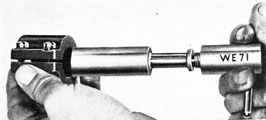
*(b) Lap reducing-valve stem:
(1) Adjust male lap, WE220, to fit valve stem hole snugly. (WE220, 37)
(2) Measure diameter of male lap WE220. (WE220, WE6)
3. Select a spare valve stem which is slightly larger than diameter measured in step (2), above. (WE6)
4. Lap spare valve stem to size (Fig. 175). (WE71, WE72, WE6)
Figure 177
5. Wash valve stem after lapping, and blow dry.
*(c) Lap reducing-valve nipple connection to seat in body, using a piece of stock having a 1/4-inch-20 tapped hole in one end.
(1) Trim butt ends of packing, if necessary, to obtain a flush joint.
(2) Slip packing on arbor of packing preforming tool. (WE234B)
(3) Slip long and short sleeves on arbor and insert arbor assembly into tool body.
(4) Place bushing against either sleeve and clamp entire assembly between vise jaws (Fig. 176).
(5) Tighten vise to form packing;
174
Figure 178
leave compression on packing for about one minute; then loosen vise and remove packing from tool. (WE234B)
(6) Wipe oil (B) around valve stem; oil (D) and insert packing (bevel end first) into body around valve stem (Fig. 177).
(7) Replace packing gland and tighten. Move valve stem back and forth several times while tightening gland, to work in packing. (422)
(8) Adjust gland until valve stem moves with a force of seven to nine pounds in either direction (Fig. 178). (422, 98)
(f) Replace washer and lock screw for packing gland. (389)
(g) Clean out 0.020-inch restriction in control chamber.
(h) Replace reducing-valve nipple connection and follower nut. (377)
(i) Blow out control pipe and replace on body. (141A)
(j) Replace reducing valve stop plug and washer. (13-14)
4. Restriction valve (not applicable to
Mk 23 Type):
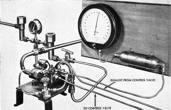
(a) Test restriction valve (Fig. 179):
Note: The restriction valve is calibrated for low-speed restriction only; the sprays act as metering devices in high speed. The restriction valve is calibrated in the same manner as are the sprays; that is, finding the time required to force six pints of water through the low-speed restrictions with a pressure of 35 p.s.i.
Proceed as follows:
(1) Place restriction valve in special holding fixture, with the hole in
the nipple on the fixture in proper alignment with the hole in the restriction valve. Clamp restriction valve in fixture. (49)
(2) Connect one nipple of holding fixture to the test lead of a correctly calibrated Spray, Check Valve, and Fuel Flask Testing Outfit. (144)
(3) Close outlet-valve cock.
Figure 179
175
Figure 180
(4) Remove water filling plug and fill bottle with water. (Do not replace plug.) (402)
(5) Remove drain cap from bottom of stand pipe and drain excess water out of bottle until no more will come out. (161, 18)
(6) Replace drain cap over end of stand pipe and replace water filling plug. (161, 18, 402)
(7) Turn on low-pressure-air inlet-valve cock and adjust reducing-valve delivery pressure to exactly 35 p.s.i.
(8) Open outlet-valve cock and make trial run to ascertain that the reduced pressure is correct and that set is in working order. Close inlet-valve cock.
(9) With trial run satisfactorily completed, repeat steps (3) through (6), inclusive.
(10) Turn on the air inlet-valve cock.
(11) Simultaneously start stop watch and open water outlet-valve cock.
(12) Snap stop watch at the moment restriction valve bows air, indicating that water is exhausted. The time found is the restriction valve time for the particular restriction under test. The time for the fuel restriction (low power) should be 144 seconds. The time for the water restriction (low power) should be 67 seconds.
(13) After restriction valve has
passed test satisfactorily, close air inlet- and water outlet-valve cocks, disconnect special holding fixture and remove restriction valve from fixture. Wipe off valve. (144, 49)
*(b) Lap restriction valve holes in body (two diameters).
(WE221, WE222, 37)
(d) Place pinion on valve stem temporarily and replace valve in body coated with oil (D), turning valve with tool on pinion until seated. Remove pinion.
(439)
(e) Remove oil plugs, fill oil holes with oil (B), and replace oil plugs. (41)
(f) Replace restriction-valve stuffing box and washer. (377)
(g) Pack stuffing box with five pieces of 1/8-inch-diameter by 2%-inch-long asbestos packing which have been soaked in oil (D) at least 12 hours, pushing each piece into place. (482)
(h) Replace and tighten gland. (4:-34)
(i) Replace pinion on end of restriction-valve stem; secure with taper pin and rivet end of pin. (166)
(j) Replace plug and washer for restriction-valve body. (427)
(k) With tool No. 439 installed over end of pinion, place push balance on end of tool at right angles and measure force to turn valve. The force required to turn
176
Figure 181
valve should be three to five pounds on a properly packed valve. (439, 98)
F. Test Assembled Reducing Valve (Fig. 181)
Note: Reducing valves for Torpedoes Mk 14 Type should always be tested with the restriction valve set for "low power". Reducing valves for Torpedoes Mk 23 Type are permanently set for "high power".
1. Test tightness of packing around valve stem:
Note: If tightness was checked in step E-3, (e), (8), above, this step will not be necessary.
(a) Remove stop plug from reducing valve body. (13-14)
(b) Insert a screw rod through the nipple connection over reducing-valve stem and push valve stem. (74)
(c) Insert a push balance through stop-plug hole until it touches reducing-valve head, and note force required to move valve. The force should be between seven and nine pounds. (98)
Note: Uniform reducing-valve action depends upon correct installation and tightness of the packing around the reducing-valve stem. It is, therefore, essential that the reducing valve be properly packed and that the packing be adjusted to impose a friction of seven to nine pounds upon the reducing-valve stem movement. The reducing-valve packing (SP 10727) currently furnished in accordance with specifications (OS 867 "Type F") is the only packing authorized, and no substitute should be installed.
(d) Replace stop plug and remove screw rod. (13-14, 74)
2. Ascertain that there is a 0.212-inch restriction in the restriction block.
3. Turn on heater and bring water to a temperature of about 200 degrees Fahrenheit.
4. Adjust precision-gage pointer to read zero.
5. Mount reducing valve on test block. (386)
177
Figure 182
6. Make the following connections:
(a) Air from banks to starting valve. (134, 218)
(b) Reduced air from reducing valve to restriction block. (134)
(c) Restriction block to atmosphere. (134)
(d) Starting valve to firing valve. (141A)
(e) Firing valve to restriction block. (141A)
(f) Reducing valve (reduced pressure) to gage. Make connection to nipple which supplies air to air check valves. (229)
(g) Control chamber on reducing valve to inlet nipple on control valve. (141A)
Note: The control valve should have been previously set on the Control Valve Test Panel to deliver the proper control-valve pressure listed in the torpedo's record book. Step G. below.
(h) Exhaust nipple on control valve to nipple on reducing valve (starting-gear return nipple). (141A)
7. Blank off remaining outlets on reducing valve. (229, 141A)
8. Perform test as follows:
(a) Charge banks to full pressure (2800 p.s.i.).
(b) Open valve from banks, permitting air to bank up to the starting valve, and stand by firing valve.
(c) Open firing valve, and note the reduced pressure obtained. Observe closely the fluctuations and variations of pressure.
Note: Immediately upon firing, the reducing-valve pressure will rise above set pressure, and then drop back to normal.
If too much oil is used during the assembly of the reducing valve, the initial pressure "jump" will increase. At the end of the run, when the air-bottle pressure drops below 1000 p.s.i., the reduced pressure will build up 10 to 15 p.s.i. above the set pressure.
(d) Continue test until pressure in air banks drops to 1000 p.s.i. Close firing valve. The test-block pressure found must be the same as that recorded in the torpedo's record book.
Note: The test-block pressure is the average reduced pressure found during the run, excluding the initial jump and the "tail off".
(e) If the correct test-block pressure is not obtained, the control valve setting must be changed to give the correct test-block pressure.
Note: If the control-valve setting is changed, the control valve must be placed in the Control Valve Test Panel and the new control-valve pressure observed. The new control-valve pressure must then be entered in the torpedo's record book. (The official control-valve pressure should always be taken from the Control Valve Test Panel; it should never be taken from a gage connected to the control-valve test nipple during the reducing-valve block test.)
(f) After a satisfactory test has been made, remove blanks and pipe connections, remove control valve, and remove reducing valve from test block.
(229, 141A, 134, 218, 386)
9. Test tightness of packing around valve
stem (step 1, above, for procedure). The
178
Figure 183
force required to move valve should still be seven to nine pounds.
G. Control Valve (Fig. 182)
1. Lap valve hole in control-valve body.
(WE147)
*2. Lap control-valve. (WE148)
*3. Chase threads and reseat seats on nipples. (WE94A, WE95, WE85, WE87)
4. Oil (C) and replace control-valve in body.
5. Clean and inspect strainer. Replace strainer, washer, and cap. (402)
6. Oil (D) and replace small spring button, spring, and large spring button in spring case.
7. With spring case in vise, (set up tight enough to hold without distorting), screw control-valve body into spring case. (402)
8. Replace blank nut with washer on test nipple. (18)
9. Replace adjusting screw and secure with clamp screws. (40)
10. Test control valve (Fig. 183):
(a) Remove blank nut with washer from test nipple on control valve (Fig. 183). (18)
(b) Loosen clamp screws for adjusting screw. (40)
Figure 184
(c) Connect control valve to pipes on Control Valve Test Panel:
(1) High-pressure line to cap on control valve. (229, 18)
(2) Control valve to bleeder valve.
(141A)
(3) Control valve test nipple to
gage. (229)
(d) Open valve in high-pressure line, first making sure that bleeder valve is open.
Figure 185
(e) By means of adjusting screw, set control valve to pressure given in torpedo record book, keeping exhaust pressure constant at 450 p.s.i., while making the adjustment.
(f) Vary the exhaust pressure over a range of approximately 100 p.s.i. by opening and closing bleeder valve. The control-valve pressure should remain constant.
179
(g) Turn off valve in high-pressure line.
(h) Tighten clamp screws for adjusting screw. (40)
(i) Open valve in high-pressure line and repeat test to make certain that adjustment was not disturbed when clamp
Figure 186
screws for adjusting screw were tightened.
(j) Remove control valve from panel and replace blank nut with washer on control-valve test nipple. (229, 18, 141A)
H. Combustion Flask and Nozzle Unit
*1. Chase threads and reseat air connection nipple on combustion flask.
(WE92, WE89)
*2. Chase threads in hole for igniter; use one-inch-20 NS-3 tap.
*3. Chase threads in holes for sprays; use 3/4-inch-20 NS-3 tap.
*4. Chase threads and reseat nipple (pipe to air-strainer body). (WE95, WE85)
*5. Run nozzle clearance tools through nozzles (Fig. 184). (WE37C, WE37D)
6. Inspect and clean interior of combustion flask.
7. Assemble sprays (Fig. 185):
(a) Clean and inspect hole in spray body.
(b) Clean, inspect whirl, and replace in body. (41)
(c) Clean, inspect plug, and replace in body. (41)
(d) Clean and inspect spray holder.
(e) Replace spray body and washer in holder. (12)
8. Test sprays as follows (Fig. 186):
(a) Connect spray to be tested to outlet pipe of a correctly calibrated Spray, Check Valve, and Fuel Flask Testing Outfit. (141A, 144)
(b) Remove plug and fill bottle with water. (Do not replace plug) (402)
(c) Remove drain cap in bottom of standpipe and drain excess water out of bottle until no more will come out.
(161, 18)
(d) Replace drain cap over end of standpipe and replace water filling plug. (161, 18, 402)
(e) Make certain that outlet valve cock is closed.
(f) Turn on low-pressure-air inlet valve cock and adjust reducing-valve delivery pressure to exactly 35 p.s.i.
(g) Open outlet valve cock and make trial run to ascertain that the reduced pressure is correct and that set is in working order.
(h) With trial run satisfactorily completed, repeat steps (b) to (e) inclusive.
(i) Turn on the air inlet-valve cock.
(j) Simultaneously start stop watch and open water outlet-valve cock.
(k) Observe pressure closely - it should remain constant at 35 p.s.i.
(l) Snap stop watch at the moment spray blows air, indicating that the water is exhausted.
180
Figure 187
(m) The number of seconds required for six pints of water to pass through the spray is its rating. This rating is stamped on the end of the spray body. Water is used in testing both the fuel and the water sprays.
(n) If necessary to change the sprays to obtain the correct delivery rate, the following is the procedure currently in use at the Naval Torpedo Station, Newport, R. I.:
(1) Remove spray body from spray holder.
(2) Remove plug and whirl from body.
(3) If increased rate of delivery is required, file tip of whirl (bottom thread) slightly.
Caution: Great care must be exercised not to remove too much stock, as the whirl may become unfit for use.
(4) If decreased rate of delivery is required, upset the lip on the bottom of the whirl a small amount.
(5) Clean, assemble spray parts, and repeat test. The correct spray rating must be obtained by this trial-and-error method.
Note: Strainers in test set must be
checked frequently for cleanliness.
(o) After spray has passed test satisfactorily, disconnect and remove it from testing outfit. (141A, 144)
9. Replace spray holders and washers in
combustion flask. (51A, 406)
*10. Replace plugs and washers in nozzle
holes. (466)
Figure 188
181
*11. Replace test plug and washer in nozzle hole. (183)
*12. Test combustion flask and nozzle unit for leaks as follows (Fig. 187):
(a) Install gasket and blanking plate over nozzle-valve hole (not applicable to Mk 23 Type). (459)
(b) Install nozzle blanking plate and gasket on nozzle unit. (227-227A)
(c) Mount combustion flask in vise with igniter hole uppermost.
(d) Fill combustion flask with water through igniter hole.
(e) Install dummy igniter. (391A)
(f) Connect lead from hydraulic pump to nipple for pipe to air-strainer body. (141A)
(g) Blank spray holder nipples, dummy igniter nipple, and main air nipple. (144, 141A, 134)
(h) Turn combustion flask in vise, so that test plug in nozzle unit is at its highest point.
(i) Remove test plug and washer from nozzle unit. (183)
(j) Pump until water starts coming out test plug hole in nozzle unit.
(k) Replace test plug and washer in nuzzle unit. (183)
(l) Pump until a hydraulic pressure of 1500 p.s.i. is obtained.
(m) Examine combustion flask carefully for leaks.
(n) After satisfactory test has been made, loosen nozzle blanking plate to release pressure. (227-227A)
(o) Remove nozzle blanking plate, valve hole blanking plate, test lead, and blanking nuts and remove combustion flask and nozzle unit from vise.
(227-227A, 459, 141A, 144, 134)
*13. Fit new nozzle valve (not applicable
to Mk 23 Type):
(a) Clean nozzle-valve bonnet.
(b) Insert new valve in bonnet.
(c) Replace packing gland. (440)
(d) Rub a small amount of grinding compound on face of valve.
(e) Secure bonnet and valve assembly
to nozzle unit. (459)
(f) Remove nozzle test plug. (183)
(g) Hold valve against seat with a piece of copper tubing inserted through nozzle test plug hole, and grind valve to seat, moving valve by means of valve stem.
(h) After grinding, remove bonnet
and valve from nozzle and examine valve.
Ridges should show an even flat seat.
(459)
(i) Remove packing gland and valve
from bonnet and wash parts thoroughly.
(440)
(j) Replace nozzle test plug. (183)
*14. Assemble nozzle valve and bonnet
assembly (not applicable to Mk 23 Type)
(Fig. 188):
(a) Insert nozzle valve in nozzle-valve bonnet.
(b) Repack stuffing box, using 41/2 inches of 3/32-inch-diameter asbestos packing soaked in oil (D). Replace packing gland, moving valve stem through stuffing box while tightening gland. Gland must be flush with, or slightly below, surface of nozzle valve bonnet when fully tightened. (440)
(c) Screw adjusting nut into operating rack by hand and secure with cotter pin. (72)
(d) Screw operating rack, with adjusting nut, on valve stem.
Note: For assembly and adjustment of nozzle valve and bonnet unit on turbine bulkhead, see Section 10.
182
Chapter 8-Section 6
MAIN ENGINE
DISASSEMBLY
With main engine clamped in overhauling stand, proceed as follows:
A. Disconnect Pipes
1. Air pipe, bulkhead to manifold (gyro spin). (229)
2. Air pipe, manifold to governor bracket (return from starting gear). (14lA)
3. Air pipe, governor bracket to turbine bulkhead (return from starting gear). (141A)
Note: Disconnect this pipe at turbine bulkhead.
4. Air pipe, bulkhead to manifold (to air strainer body). (141A)
5. Air pipe, bulkhead to manifold (to control valve). (141A)
6. Air pipe, bulkhead to manifold (to starting gear). (14lA)
B. Remove Preheater Pipe
1. Remove wire and two screws from bracket for preheater pipe. (72, 49, 64)
2. Remove preheater pipe, with bracket, from turbine bulkhead. (134)
C. Remove Turbine Bulkhead
1. Remove cotter pins and nuts from "A" frame studs on bulkhead. (72, 356)
2. Remove turbine bulkhead.
Note: It may be necessary to tap off with a soft lead hammer.
D. Remove Oil Pump
1. Remove oil pipe from oil pump to manifold (suction). (229)
Note: When torpedoes have been converted for smokeless running, (NavOrdOrdalt 1654), this pipe will be from the manifold to the water lubrication check valve.
2. Remove oil pipe from oil pump to spindle casing. (14lA)
3. Disconnect short pipe (oil connection to cross head) at pump; push nut clear of nipple and disconnect oil connection elbow from lower oil connection to crosshead. (141A, 144)
4. Remove cotter pins and nuts from studs for oil pump. (72, 407)
5. Remove oil pump from "A" frame.
E. Remove Governor Body Assembly and Bracket
1. Remove air pipe, governor bracket to turbine bulkhead. (141A)
2. Remove wire, holding screws, and journal caps. (72, 41)
3. Remove governor body assembly.
4. Remove wire, holding screws, and
bracket. (72, 49)
5. Remove spring button and spring
from lower "A" frame.
F. Disassemble Gear Train
1. Remove top bearing and top bearing holder:
(a) Remove wire, and loosen two lock screws for top bearing cover. (72, 41)
(b) Remove top bearing cover. (13-14)
(c) Remove cotter pin, clamping screw, and clamp for top bearing. (49)
(d) Remove ball bearing and spacer for top bearing.
(e) Remove wire and holding screws for top bearing holder. (72, 49)
(f) Remove wire and back off dowel screw in top bearing holder. (72, 48)
(g) Remove oil bolt in top bearing holder. (356 or 141A)
(h) Remove top bearing holder.
2. Remove two locking screws from second turbine wheel lock nut and remove lock nut. (41, 433)
3. Bend lock washer clear, and remove oil pump worm and lock washer. (40, 402)
4. Place holding clip on turbine wheels. (454)
5. Remove lower lock nut for second turbine spindle. (391A)
6. Remove washer for lower bearing.
7. Remove 15 balls from lower bearing.
183
8. Remove cotter pins, nuts, and clamp bolts; and remove lower, middle, and upper bearing locking levers from spindle casing.
(92, 386)
9. Remove wires and loosen "A" frame screws to spindle casing 3/4, of a turn. Insert wedge in split end of spindle casing at lower bearing to spread threads in spindle casing. (386, 231)
10. Remove lower bearing from spindle casing. (452)
11. Remove inner race for lower bearing.
12. Remove the remaining 15 balls for lower bearing.
13. Remove upper washer for lower bearing.
14. Remove holding clip from turbine wheels, and remove second turbine spindle with turbine wheel. (454)
15. Remove lower driving pinion from spindle casing.
16. Remove turbine wheel from second turbine spindle and remove four keys from spindle, prying out with screw driver in milled slots of keys. (41)
Note: It may be necessary to use soft lead hammer to loosen wheel.
17. Remove two locking screws and turbine wheel lock nut from first turbine spindle. (41, 233)
18. Remove turbine wheel from first turbine spindle.
Note: It may be necessary to use a soft lead hammer to loosen wheel.
19. Remove four keys from first turbine spindle by prying out with screw driver in milled slots of keys. (41)
20. Remove wire, screws, and turbine oil guard. (92, 41)
21. Remove copper-asbestos compression washer.
22. Remove oil deflector ring, taking care not to distort it.
23. Insert wedge in spindle casing at upper bearing to spread threads, and remove outer race for upper bearing from spindle casing. (231, 228)
24. Remove 18 balls for upper bearing.
25. Remove first turbine spindle from spindle casing.
26. Remove upper race for middle bearing.
*27. Remove lower race for upper bearing by tapping with rawhide maul.
28. Remove 15 balls from middle bearing in spindle casing.
29. Remove oil connection, two copper washers, and steel washer from lower end of crosshead. (141A or 150)
30. Remove oil connection and copper washer from upper end of crosshead. (96A)
31. Remove wire and holding screws for upper "A" frame to spindle casing.
(72, 386)
32. Place holding clip on main driving gears. (454)
33. Remove cotter pins and nuts on studs; and slide engine strut aft on propeller shafts. (72, 356)
Note: When removing strut, catch balls in bearing.
34. Remove wire and holding screws for lower "A" frame to spindle casing. (72, 386)
35. Remove "A" frames, steel "A" frame thrust washers, and spindle casing from gear train.
Note: When removing the above assembly, it may be necessary to tap the "A" frames lightly with a lead hammer, at the same time holding spindle casing to prevent its falling.
36. Remove middle bearing from spindle casing. (452)
37. Place main driving gears in a vertical position. Remove holding clip. (454)
38. Remove two outer bronze thrust washers on ends of crosshead.
39. Remove two main driving gears.
40. Remove driving pinion bushings from crosshead.
41. Remove two bronze thrust washers from crosshead inner ends.
42. Remove forward thrust bearing race for after propeller shaft from spindle casing.
43. Remove thrust bearing and after bearing race from after propeller shaft.
44. Withdraw after propeller shaft from inside of forward propeller shaft.
48. Remove U-seal retainer, U-seal, and bushings from forward propeller shaft.
49. Remove forward propeller shaft from overhauling stand and slide off engine strut.
*50. Remove forward strut thrust bearing race from forward propeller shaft. Tap gently with a lead hammer.
*51. Remove after bevel gear from forward propeller shaft.
*52. Remove forward bevel gear from after propeller shaft.
*53. Remove after thrust bearing race from engine strut.
Note: Drive the race out of strut by inserting a piece of 1/4-inch round brass stock through holes in strut.
The above completes the disassembly of the main engine.
OVERHAUL, ASSEMBLY, AND TEST
G. Propeller Shafts
1. Place shafts between knife-edge rollers or between centers on shaft straightening press, and with a dial indicator, measure
amount out of true by turning shaft slowly (Fig. 189). If shafts are out of true by more than 0.005 inch, mark high spots with chalk.
*2. If above step indicated that shafts are out of true by more than 0.005 inch, place shafts on V-blocks of shaft-straightening press, with chalk mark uppermost. Place a piece of brass stock over portion of shaft to be straightened, and tighten press to straighten shaft (Fig. 190). Re-check alignment as in step 1, above.
3. Clean shafts; blow out all grease holes with air. See that outer and inner bearing surfaces of shafts are clean and smooth. Note if there is any indication of friction on bearing surfaces, in which case it will be necessary to stone rough surfaces smooth.
*H. Forward and After Bevel Gears
1. Dress off any burrs which may be present on propeller-shaft keys.
2. With bench marks on bevel gears lining up with bench marks on shafts, replace bevel gears in shafts. Use a piece of soft brass or copper stock against gears and drive on with a hammer until properly seated.
Note: Great care must be exercised in lining up gears on keys, because if a small amount of metal is sheared off keys while driving gears on shafts, this metal will lodge on shaft shoulders and change longitudinal clearances of shaft assemblies.
*I. Forward Strut Thrust-Bearing Race
1. Examine race for wear or corrosion. If necessary, polish in bench lathe.
Figure 189
185
Figure 190
2. Assemble forward strut thrust-bearing race on forward propeller shaft (it may be necessary to tap in place with a soft lead hammer) slipping on from after end of shaft. Bearing surface must face aft, and key slot in race must engage key on shaft.
*J. AFTER STRUT THRUST-BEARING RACE
1. Examine race for wear or corrosion. If necessary, polish in bench lathe.
2. Clean race and strut and insert race into strut.
K. Check Alignment of Top Bearing Holder With Spindle Casing (Fig. 191)
1. Place feet of "A" frames on bench and assemble to spindle casing.
Figure 192
186
Figure 193
2. Replace holding screws for spindle casing, but do not tighten.
3. Replace steel "A" frame thrust washers.
4. Install crosshead between "A" frames and secure with upper oil connection and washer and lower oil-connection assembly.
(96A, 141A or 150)
5. Assemble strut to "A" frames and secure with nuts. (356)
6. Tighten holding screws for spindle casing. (386)
7. Install top bearing holder and secure. (49, 141A)
8. Check to see that all nuts and screws are tight.
9. Place two parallel bars on a leveled surface plate, and place unit on parallel bars. (453)
10. Screw small aligning bushing into lower bearing end of spindle casing.
11. Screw large aligning bushing into upper bearing end of spindle casing.
12. Insert aligning bushing into top bearing holder.
13. Insert aligning bar through bushings in spindle casing. If top bearing holder is properly aligned with spindle casing, the aligning bar will slide freely into the top bearing-holder aligning bushing.
14. Remove unit from surface plate and disassemble. (96A, 141A or 150, 356, 386)
L. Inspect, Assemble, and Adjust Gear Train
1. Thoroughly clean all parts. Inspect parts for proper size, pits, corrosion, wear, etc. Oil (B) all parts before assembling.
NOTE: When torpedoes have been converted for smokeless running, (NavOrd Ordalt 1654), all parts should be brushed with oil (T) before assembling. No oil (B) should be used.
Figure 194
187
2. Slip engine strut over forward propeller shaft and clamp shaft in overhauling stand.
(a) Assemble outer race into sleeve, making certain that race is flush with after end of sleeve and that holes in sleeve are nearest crosshead.
(b) Place sleeve and outer race, assembled, into after bevel gear, around forward propeller shaft (Figs. 192 and 193).
4. Assemble parts on after propeller shaft in the following order (Fig. 193):
(a) Crosshead and crosshead bushing -note that recessed end of crosshead bushing is facing aft.
(b) Spacer for crosshead bushing.
(c) Bearing washer (concave).
(d) Inner race (convex).
(e) Retainer and balls.
5. Slide after propeller shaft assembly into forward propeller shaft (Fig. 193). Make certain that bearing washer is properly lined up.
6. Assemble propeller shaft bushings, U-seal, and U-seal retainer in the following order (Fig. 194):
(a) Long bushing.
(b) Short bushing.
(c) U-seal and U-seal retainer-note that U-seal is forward.
Note: Use a spare bushing to push long and short bushings into place before assembling U-seal and U-seal retainer.
Figure 195
Damage to U-seal may result if bushings are pushed into place with U-seal and U-seal retainer.
7. Replace two bronze thrust washers on crosshead inner ends-note that rounded surfaces of washers are toward center.
8. Check size of driving-pinion bushings, using GoNoGo plug gage (Fig. 195). (WE25)
9. Replace driving-pinion bushings on crosshead.
10. Line up propeller shafts:
(a) Insert aligning tool over ends of shafts, with keys of shaft engaging keyways of tool. Secure tool with nut.
(450, 229)
(b) Place spirit level on flat part of aligning tool. Loosen clamp on overhauling
Figure 196
stand; turn assembly level; and tighten clamp on overhauling stand.
11. Place main driving gears over crosshead spindles and bushings in such a way that when a spirit level is laid across the teeth of both main driving gears and registers level, the driving pinions are in full mesh with the forward and after bevel gears (Figs. 196 and 197).
188
Note: The main driving gears are not marked for upper or lower, but are easily identified, as the upper gear is darkened by the action of heat. This gear should be assembled on the crosshead spindle having a shallow threaded hole in its upper end. This
Figure 197
spindle should be on your right side during assembly.
12. Place holding clip over main driving gears. (454)
13. Replace after race (of after propeller-shaft bearing) on after propeller shaft (Fig. 198).
14. Replace balls and retainer on after propeller shaft.
15. Replace main driving gear washers over crosshead spindles (Fig. 198).
16. Assemble spindle casing:
Note: Fig. 199 shows arrangement of parts in spindle casing.
Figure 198
(a) Inspect spindle casing, making certain that dowel pins are tight and straight and that oil channels and hole in oil-connection nipple are clear.
Figure 199
(b) Insert wedge into spindle casing near middle bearing (below threads for race). (231A)
(c) Replace outer race for middle bearing in spindle casing, using depth-gage tool to locate. Remove wedge (Fig. 200). (424, 452)
(d) Replace middle bearing locking lever, bolt, nut, and cotter pin. Do not set up on bolt. (386, 72)
*(e) Replace lower race for upper bearing on upper end of first turbine-wheel spindle.
(f) Replace upper race for middle bearing on end of first turbine-wheel spindle.
(g) Apply grease (S) and place 15 balls in middle-bearing race.
NOTE: When torpedoes have been converted for smokeless running (NavOrdOrdalt 1654), use oil (T).
(h) Note that taper on first turbine-wheel spindle fits snugly into tapered hole in turbine-wheel. By rubbing spotting fluid on the tapered end of spindle and turning it in tapered hole, high spots may be noted. It is important that this fit is snug, as otherwise the turbine may wobble out of true.
(i) Insert first turbine spindle assembly into spindle casing (Fig. 201).
(j) Insert wedge into upper bearing end of spindle casing. (23lA)
189
Figure 200
Figure 201
(k) Apply grease (E) and place 18 balls on lower ring for upper bearing.
(1) Replace outer race for upper bearing (Fig. 202).
(m) Screw outer race down hard against balls, until no up-and-down play of first turbine spindle is noted. (452)
(n) Observe position of locking notch in relation to slot for upper ball-race locking lever. Unscrew ball race three full notches, lining up nearest notch with locking lever slot. This adjustment should give 0.018 'inch end play for first turbine spindle. (452)
(p) test middle bearing for trueness by placing spindle casing on surface plate and using dial indicator on top of first turbine spindle.
17. Replace forward race (for after propeller-shaft thrust bearing) on spindle casing.
Figure 202
18. Replace steel "A" frame thrust washers in "A" frames.
19. Line up upper "A" frame with spindle casing and crosshead, and tap into place with soft lead hammer (Fig. 203).
20. Replace washer and upper oil connection for crosshead, but do not tighten. (96A)
21. Replace spindle-casing holding screws and set up hand-tight.
22. Line up lower "A" frame with spindle casing and crosshead, and tap into place with a soft lead hammer.
*23. Replace packing in lower oil connection assembly:
Note: If, while running main engine in test stand, it is noticed that lower oil-connection assembly leaks, even with packing-gland nut set up tight, it will be necessary to renew packing.
(a) Remove wire and keep screw for packing-gland nut. (72, 41)
(b) Unscrew packing-gland nut and slide clear. (141A)
190
Figure 203
(c) Remove old packing and repack, using about six inches of 3/32-inch diameter asbestos packing. (482)
(d) Replace gland nut and tighten.
(141A)
(e) Replace keep screw and secure
with wire. (41, 72)
24. Replace small copper washer, steel washer, and large copper washer, in order named, on lower oil connection.
25. Replace lower oil-connection assembly in crosshead, but do not set up tight. (141A or 150)
26. Replace spindle-casing holding screws and set up hand-tight.
27. Place engine strut over "A" frame bolts and screw nuts in place temporarily. (356)
28. Place parallel bars on "A" frames. (Pins in parallel bars fit into "A" frame holes for bulkhead studs.) (453)
29. Unclamp and remove main engine assembly from overhauling stand and place on leveled surface plate, shaft end up and parallel bars resting on surface plate. (453)
Note: It is desirable to have three men for the above step. Insert a piece of stock through holes in main driving gears. One man should be at each end of this piece of stock, using one hand to hold shaft. The other man should unclamp assembly from overhauling stand, hold parallel bars on "A" frames, and help place assembly on surface plate.
30. Remove nuts and slide engine strut up on shaft and hold clear. (356)
31. Place 22 balls on forward race of engine-strut thrust bearing.
32. Drop strut down over balls, at the same time lining up the "A" frame bolts in strut (Fig. 204).
33. Replace nuts on "A" frame bolts, but do not tighten.
34. Rock gear-train assembly by hand several times. Note that legs on "A" frames are properly seated on parallel bars and that parallel bars are flush on surface plate, thus ascertaining that assembly is in proper alignment (Fig. 205). (WE2A)
Figure 204
191
Figure 205
35. Proceed to tighten and secure nuts and screws as follows:
(a) Nuts for bolts for "A" frames to strut. (356)
(b) Cotter pins for above. (72)
(c) Oil connection, lower.
(141A or 150)
(d) Oil connection, upper. (96A)
(e) Holding screws for spindle casing and "A" frames, tightening up evenly. (386)
(f) Wire holding screws securing "A" frames to spindle casing. (72)
36. Place dial indicator on after face of after bevel gear and set indicator to zero. Lift gear upward as far as it will go and note reading on dial indicator. This reading (clearance) should be 0.025 inch to 0.035 inch. If not, note if bearing races for engine strut balls are properly seated against shoulder of shaft and recess in strut (Fig. 206).
37. Place dial indicator on one tooth of forward bevel gear and set indicator to zero. Lift gear upward as far as it will go and note reading on dial indicator. This reading (clearance) should be 0.025 inch to 0.045 inch. If not, it will be necessary to disassemble and find cause. (See Note under step *H-2 for possible cause.)
38. Remove assembly from surface plate; remove parallel bars from "A" frames and clamp gear train assembly in overhauling stand.
39. Replace oil-deflector ring and copper-asbestos compression washer.
Note: Figure 207 shows arrangement of parts covered by steps 39 through 41.
40. Replace turbine oil guard and secure with four screws. Wire screw heads. (41, 72)
Note: When torpedoes have been converted for smokeless running (NavOrd Ordalt 1654), make certain that no oil remains on the turbine oil guard.
Note: Place special screw in countersunk hole on the forward side of guard.
41. Install first turbine-wheel:
(a) Check parting of segments in first turbine wheel.
(b) Check turbine wheel for trueness by laying it on a surface plate and trying 0.003-inch feeler gage between outer edge of wheel and surface plate. (WE2A)
(c) Insert four keys in keyways on first turbine spindle. Note that key
Figure 206
192
Figure 207
numbers correspond to keyway numbers and that milled slots are on top for insertion of screw driver for removal.
(d) Replace first turbine wheel on spindle, with assembly marks lined up. Tap in place with lead hammer.
Note: When torpedoes have been converted for smokeless running, (NavOrd Ordalt 1654), make certain that no oil remains on the turbine wheel.
(e) It is good practice to insert a 0.002-inch feeler between keys on spindle and keyways in turbine wheel. If feeler will not pass between a key and its keyway, turbine wheel will hang up on that key and will not run true.
(f) Replace lock nut for first turbine wheel setting up tight until bench marks are in line. (433)
(g) Replace two locking screws for lock nut.
(41)
(h) Turn first turbine wheel and make certain that it does not rub against turbine oil guard or upper "A" frame.
42. Check first turbine wheel for alignment with spindle and bearings:
(a) Level gear train assembly in overhauling stand. Lay one parallel bar across after side of engine "A" frame as a seat for dial indicator.
(b) Place pointer of dial indicator on outer edge of wheel. Set indicator on zero and note position with chalk. Turn wheel one complete revolution, indicating every five degrees. The wobble of the first turbine wheel should not exceed 0.005-inch.
(c) Upset edges of locking-screw holes with a center punch.
43. Turbine bulkhead:
(a) Examine threads on nozzle studs. Note that studs are tight. Loose studs should be resoldered. Examine nipples on turbine bulkhead. Remove burrs or cross threads with thread combs or finger dies. Note that bearing surface for speed change mechanism is free of burrs and that screw holes are clean (not applicable to Mk 23 Type). Note particularly that nozzle flange seat is clean and free of burrs.
(b) Replace turbine bulkhead on "A" frame and secure with nuts. Do not replace cotter pins. (356)
44. Adjust clearance between first turbine wheel and nozzle plate:
(a) Clean nozzle flange seat, and, with depth micrometer, measure distance from flange seat to turbine wheel, turning wheel to obtain measurements in several
Figure 208
193
Figure 209
wheel positions (Fig. 208). Compute the average of about five readings. (WE9)
(b) With depth micrometer, measure the distance that the nozzle plate projects out from the nozzle flange. Take these measurements opposite each nozzle hole and compute the average of the readings (Fig. 209). (WE9)
(c) With micrometer, measure thickness of gasket at several points and compute the average of the readings (Fig. 210). (WE5)
(d) Use the following formula to obtain the clearance between the first turbine wheel and the nozzle plate:
Clearance = average reading of step (a) plus average reading of step (c) minus average reading of step (b). The clearance, to be correct, must be 0.057-inch to 0.062-inch.
Example: Assume that the average of readings taken in step (a) is 0.471-inch; the average thickness of gasket, step (c), is 0.028-inch; and the average of readings taken in step (b) is 0.439-inch.
Clearance = 0.471-inch plus 0.028-inch minus 0.439-inch = 0.060-inch.
This clearance is satisfactory because it is within the range indicated above
(0.057-inch to 0.062-inch). Should the clearance vary from that allowed, it will be necessary to readjust the middle and upper bearings. The procedure is as follows:
(e) Turn gear-train assembly right-side-up; remove turbine bulkhead and locking levers for middle and upper bearings. (356, 386, 72)
(f) Should less clearance be desired, move middle and upper bearings to the right by the same amount; should more clearance be desired, move middle and upper bearings to the left by the same amount. Turning the bearings one notch in either direction will increase or decrease the clearance by 0.006-inch.
(g) Example: Suppose 0.010-inch
more clearance is desired between nozzle plate and first turbine: Slip wedge between split portion of spindle casing in line with middle bearing and observing notch for line-up with split in casing; turn middle bearing race two notches to the left; change wedge to split in line with upper bearing, and turn upper bearing race two notches to the left.
(h) When both bearing races have been turned two notches to the left, replace locking levers and proceed to reassemble. After measuring, it will be found
Figure 210
194
Figure 211
that clearance has been increased by 0.012-inch, which is the closest to clearance desired.
Note: Should it be difficult to turn bearing races in the spindle casing when making the above adjustments, even when using wedge in split portion of spindle casing, it may be necessary to remove the turbine and oil guard and back off the holding screws for "A" frame to spindle casing about two turns each.
(i) Remove turbine bulkhead (356)
45. Assemble second turbine wheel on spindle, and check alignment:
(a) Check parting of segments in second turbine wheel.
(b) Check turbine wheel for trueness by laying it on a surface plate and trying 0.003-inch feeler gage between outer edge of wheel and surface plate. (WE2A)
(c) Insert four keys in keyways on second turbine spindle. Note that key numbers correspond to keyway numbers and that milled slots are on top end for insertion of screw driver for removal.
(d) Replace second turbine wheel on spindle, with assembly marks lined up. Tap in place with lead hammer.
Note: When torpedoes have been converted for smokeless running, (NavOrd Ordalt 1654), make certain that no oil remains on the turbine wheel.
(e) It is good practice to insert a 0.002 inch feeler between keys on spindle and keyways in turbine wheel. If feeler
will not pass between a key and its keyway, turbine wheel will hang up on that key and will not run true.
(f) Replace lock nut. Screw down tight until assembly marks are lined up.
(g) Replace two locking screws for lock nut. (41)
(h) Place assembled spindle and wheel in aligning fixture (SG 2853), and attach dial indicator. (WE10)
Figure 212
195
(i) Adjust indicator to outer edge of turbine wheel and set on zero (Fig. 211).
(j) With chalk, mark a reference point in line with indicator pointer. Turn wheel one complete revolution and read dial indicator every five degrees. Wobble of wheel should not exceed 0.005-inch.
(k) Remove wheel and spindle assembly from fixture.
(l) Upset edges of locking screw holes with a center punch.
46. Assemble second turbine wheel and spindle to gear train:
(a) Insert second turbine spindle into first turbine spindle.
(b) Turn gear train over and place holding clip over edges of both turbine wheels (Fig. 212). (454)
(c) Replace two keys for lower driving pinion on second turbine spindle. Note that numbers on keys correspond with numbers in key slots and that milled ends of keys are facing out.
(d) Replace lower driving pinion on spindle. Note that assembly marks are lined up and that gear end of pinion is facing out.
(c) Place 15 balls on upper washer, around inner race.
(d) Replace outer ball race. Screw race down to balls and back off about one turn (to give clearance between turbines).
(e) Place 15 balls in outer race.
(f) Replace lower bearing washer.
(g) Replace lower lock nut for second turbine spindle and tighten. (391A)
(h) Replace lock washer for oil-pump worm.
(i) Replace oil-pump worm and tighten. (402)
(j) Insert screw driver through one of cutaway spaces in lock nut and bend lock washer up flush with face of oil pump worm to lock worm. (41)
Figure 213
48. Install top bearing holder and top bearing (Fig. 213):
(a) Turn assembled gear train right-side-up. Clean and inspect top bearing holder. Note that dowel pins are straight and tight in top bearing holder. Note that small oil restriction in the top bearing holder is clear. If necessary to free this hole, use number-80 drill.
(b) Replace top bearing holder on upper "A" frame and secure with six holding screws and one dowel screw. (49, 48)
Note: Dowel screw fits into hole in the after arm of the bearing holder.
(c) Replace washer and oil bolt in top bearing holder. (141A)
196
Figure 214
(d) Wire holding screws for top bearing holder, wiring oil bolt to dowel screw. (72)
(e) Replace spacer over second turbine-wheel spindle. Note that beveled end of spacer is assembled in down position.
(f) Replace top bearing on spacer.
(g) Replace clamp for top bearing in slot in end of second turbine-wheel spindle.
(h) Replace screw for clamp and secure with cotter pin. (49, 41, 72)
49. Adjust clearance between first and second turbines:
(a) Insert wedge in split in spindle casing and turn lower ball race up or down until proper clearance (0.060-inch) is obtained, using two thickness-gage tools at opposite points between the turbine-wheels (Fig. 214). (231A, 452, 424)
(b) If notch in ball race is out of line with split in spindle casing, with clearance between turbines equal to 0.060-inch,
Figure 215
turn to nearest notch in line for more or less clearance, as a plus or minus tolerance between one notch is allowed.
(a) Place test ring on machined seat in top-bearing holder. (WE235)
(b) Place micrometer depth gage across top of test ring and measure distance to top of clamping screw with second turbine spindle raised (Fig. 215).
(WE9)
Note: The above measurement will be approximately 0.153-inch.
(c) With top bearing cover upside down, place micrometer depth gage across seat on threaded end of cover, and measure distance to center of cover (Fig. 216).
(WE9)
Note: The above measurement will be approximately 0.437-inch.
(d) Measure width of test ring. It should be about 0.500-inch. (WE5)
(e) Subtract measurement found in step (c) from width of test ring. Example:
0.500
0.437
_____
0.063
Note: The difference obtained by the above subtraction gives the amount by which the test ring height (width) differs from the depth of the cover. In this case, the difference is 0.063-inch.
(f) Subtract difference found in step (e) from measurement found in step (h). Example:
0.153
0.063
_____
0.090
Note: The above computation gives the clearance which exists between the clamping screw and the inside of the cover when the latter is assembled to the top bearing holder and when the engine is running. In the example, the clearance is 0.090-inch. To be satisfactory, the clearance must be not less than 0.050-inch.
(g) Place micrometer depth gage across top of top bearing holder and measure distance to inside shoulder of bearing holder. (WE9)
Note: The above measurement will be approximately 0.316-inch.
(h) With micrometer depth gage still across top of bearing holder, raise second turbine spindle, and measure distance to top of bearing. (WE9)
Note: The above measurement will be approximately 0.272-inch.
(i) Subtract reading found in step (h) from reading found in step (g). Example:
0.316
0.272
_____
0.044
Note: The above difference gives the distance from the bearing to the inside shoulder of the bearing holder when the engine is running.
(j) With top bearing cover upside down, place micrometer depth gage across seat on threaded end of cover, and measure distance to inside shoulder of cover.
(WE9)
Note: The above measurement will be approximately 0.120-inch.
(k) Subtract difference found in step (i) from reading found in step (j).
Example:
0.120
0.044
_____
0.076
Note: The above computation gives the clearance which exists between the bearing and the shoulder of the cover when the latter is assembled to the top bearing holder and when the engine is running. In the example, the clearance is 0.076-inch. To be satisfactory, the clearance must be not less than 0.050-inch.
51. Replace cover and tighten. Tighten
lock screws for cover and wire screw heads.
(13-14, 41, 72)
M. Replace Oil Pump (Fig. 217)
Note: See step S for disassembly. overhaul, assembly, and test of oil pump.
1. Mesh teeth of worm wheel with oil-pump worm, and replace oil pump on studs of lower "A" frame.
2. Replace four nuts on studs for oil-pump and tighten. Secure nuts with cotter pins. (141A. 41, 72)
3. Connect lower oil connection assembly to oil-pump. (141A)
198
Figure 217-Oil Pump Governor and Piping Assembly-(A) Governor gear (on oil pump); (B) Gear on governor; (C) Governor body assembly; (D) Oil to spindle casing; (E) Oil pump; (F) Lower oil-connection assembly; (G) Air from starting gear; (H) Air to reducing valve; (I) Governor bracket; (J) Journal cap
4. Replace oil pipe from oil-pump to spindle casing, and secure. (141A)
5. torpedoes converted for smokeless running (NavOrd Ordalt 1654). After the oil pump has been installed, apply low pressure air (125 psi) to the intake side of the oil pump to clear the oil passages. Check the lead to the top bearing to ascertain that the air comes through to that point. Remove the top bearing cover for accomplishing this test.
N. Replace Governor Bracket and Governor
Body Assembly (Fig. 217)
Note: For disassembly, overhaul, assembly, and test of governor, see step T.
1. Replace spring and spring button in lower "A" frame.
2. Replace governor bracket and secure with holding screws and wire. (49, 72)
3. Replace governor body assembly.
4. Replace journal caps and secure with holding screws and wire. (41, 72)
O. Replace Pipes on Governor Bracket (Fig. 217)
1. Replace pipe, manifold to bracket, (from starting gear). (141A)
2. Replace pipe, bracket to turbine bulkhead. (14lA)
P. Replace Turbine Bulkhead and Pipes on After Side of Turbine Bulkhead
1. Replace turbine bulkhead on engine "A" frames and secure with nuts and cotter pins. (356, 41, 72)
2. Connect starting-gear return pipe (from governor bracket) to nipple on after side of bulkhead. (141A)
3. Replace gyro spin pipe on nipple on after side of bulkhead. (229)
4. Replace three air pipes on nipples on after side of turbine bulkhead to manifold for the following:
(a) Air strainer. (141A)
(b) Control valve. (141A)
(c) Starting gear. (141A)
Note: These three pipes are clamped together, and it should not be necessary-to separate them for assembly.
5. Connect preheater pipe to nipples on bulkhead and tighten. Secure preheater pipe to top-bearing holder and upper "A" frames with screws and wire. (134, 49, 64, 72)
Figure 218
199
Q. Line up Pipes to Manifold
1. Clamp aligning fixture (SG 2852) loosely on lower "A" frame.
2. Assemble spacing rods to aligning fixture and slide fixture on "A" frame until spacing rods contact turbine bulkhead. Clamp fixture tightly on "A" frame. (72)
3. Line up and connect pipes to nipples on aligning fixture and tighten (Fig. 218) (229, 14lA)
4. Tighten pipe nuts on turbine bulkhead nipples. (229, 14lA)
5. Disconnect pipes from aligning fixture and remove fixture. (229, 14lA, 72)
The main engine is now ready for test.
R. Test Main Engine
Note: When torpedoes have been converted for smokeless running, (NavOrd Ordalt 1654), omit Steps 6, 8, (14 last 5 words only), 17 and 18.
1. Turn on heater switch and allow water in pre-heater of Main Engine Test Stand to come to 205 degrees Fahrenheit.
2. Install tail bearing sleeve and adapter ring.
3. Install test nozzle and test plate on turbine bulkhead.
4. Install main engine in test stand.
5. Connect air pipe and gage pipe to test nozzle.
6. Connect oil pipe from oil nipple in drain pan of test set (this nipple leads to oil tank) to oil pump on main engine. (144, 229)
7. Fill oil cup on tail bearing with oil (B).
8. Fill oil tank on panel board with oil (B) and open oil valve.
9. Crack air inlet valve until 10 p.s.i. nozzle pressure is obtained, and permit engine to run at slow speed until oil pump has forced oil to all parts of the system.
10. Place guard over engine and tighten down wing nuts.
11. Open air inlet valve more until engine speed, as read on hand tachometer held to after propeller shaft, is at test speed of 700 r.p.m.
12. Keep engine running at test speed for two minutes, and listen to engine. (With a little experience, one can judge from the sound of the running engine whether or not the bearing clearances are correct.)
13. Find the run-down time by starting stop watch and closing air inlet valve at the same time. Note time when engine stops completely. The run-down time should not be less than 55 seconds.
14. After satisfactory test has been made, turn off switch for preheater and turn off oil valve.
15. Remove guard from engine.
16. Disconnect air pipe and gage pipe from test nozzle.
17. Disconnect oil pipe.
18. Connect suction pipe on pump (manifold to pump). (229)
19. Remove main engine from test stand.
20. Remove test nozzle from turbine bulkhead.
21. Install water lubrication check valve to pump.
(229)
The above completes the overhaul, assembly and test of the Main Engine, ready for assembly in the afterbody.
S. Oil Pump
Note: When torpedoes have been converted for smokeless running (NavOrd Ordalt 1654 ), the oil pump is to be tested as described below. After the test, however, all excess oil is to be drained from the pump and the exterior is to be wiped dry. The gears shall then be given a light coat of oil (T).
1. Test oil pump:
(a) Fill supply tank on Universal Oil Pump Test Stand with oil (B) by pouring oil into measuring tank and opening drain valves. Note that oil supply valve is closed.
Note: The temperature of the oil should be about 80 degrees Fahrenheit.
(b) Install short pinion on motor shaft.. (41)
(c) Install proper suction-pipe assembly on test stand and connect vacuum-gage lead to it. (229)
Note: It is important that all connections in the suction-pipe assembly be absolutely tight. Other - wise, an improper vacuum reading will result.
(d) Mount pump on test stand, and connect suction pipe to pump. Draw up on holding screws evenly, noting that gears align properly. Turn supporting screw up until it contacts oil-pump body. Adjust supporting screw to obtain proper mesh of gears. (217)
(e) Connect oil delivery pipes from pump to test stand. (141A)
200
(f) Fill pump and pipe system with oil by opening supply valve; open gage pet cocks and start motor. Note that all connections are tight, and that pump is delivering oil to the measuring tanks. Stop motor.
(g) Close supply valve. It is important that this valve is closed tight in order to obtain an accurate vacuum reading.
(h) Start motor and allow pump to run at 440 to 445 r.p.m. until a constant reading is obtained on the vacuum gage. This vacuum should be not less than 25 inches of mercury.
Note: Most frequent causes of leakage are in order named:
(1) Leakage around pump shaft bearings. To remedy, install an oversize pump shaft.
(2) Excessive clearance between pump gears and cover. To remedy, lap seat for cover on pump body.
(3) Leakage around plug in suction chamber. To remedy, change washer under plug.
(i) Stop motor.
(j) Open supply valve.
(k) Drain all oil from measuring tanks: then close drain valve.
(l) Start motor and run pump at 440 to 445 r.p.m. for one minute.
Note all gage readings during the run. They should be not less than the minimum values listed below:
Minimum Vacuum
(Inches of Mercury)
On Test
Pumping Oil
25
7
Minimum Delivery Pressures
(P.S.I.)
Crosshead
Turbine Spindle
28
32
(m) Stop motor at end of one minute. and note quantities of oil in measuring tanks. These quantities should be not less than the minimum values listed below:
Minimum Oil Delivery
(Pints)
Crosshead
Turbine Spindle
Total Delivery
1.5
1.6
3.1
(n) Close supply valve.
(o) Disconnect all pipes from oil pump and remove pump from test stand.
(229. 141A, 217)
The above test is made to facilitate inspection of condition during overhaul.
Figure 219
201
2. Disassemble oil pump:
(a) Remove cotter pin and nut for governor gear on oil-pump shaft.
(72,:389)
(b) Pry off governor gear. (40)
(c) Remove six screws and cover plate. (41)
(d) Remove worm gear and shaft assembly.
(e) Remove upper pump gear.
(f) Remove stud- and lower pump gear.
(40)
(g.) Remove four screws and oil connection (to spindle casing). (41)
(h) Remove cotter pin, nut, washer, and worm gear from shaft. (72, 389)
(i) Remove plug and washer for after (suction) end of pump body. (436)
3. Overhaul and assemble oil pump (Fig. 219):
(a) Thoroughly clean and inspect all
parts. Remove all burrs. Chase threads and reface seat on nipples.
(WE94, WE95, WE83, WE85)
(b) Replace washer and plug. (436)
(c) Replace oil connection (to spindle casing) and secure with four screws. (41)
Figure 220
202
(d) Replace worm gear on shaft and secure with washer, nut, and cotter pin. (389, 72)
When torpedoes have been converted for smokeless running (NavOrd Ordalt 1654), the worm gear, the governor gear, and the shaft bearings are to be given a coat of oil (T).
(e) Insert worm gear and shaft assembly into bearing in body.
(f) Replace upper pump gear.
(g) Replace lower pump gear and stud. (40)
(h) Replace cover plate and secure with six screws. (41)
(i) Replace governor gear and secure with nut and cotter pin. (389, 72)
Figure 221
4. Test assembled oil pump. (See step 1.)
For installation of oil pump on main engine, see step M.
T. Governor and Governor Bracket
1. Test governor and bracket assembled:
(a) Secure governor bracket assembly to block on Universal Starting Gear and Governor Testing Stand with four screws.
(49)
(b) Assemble governor body assembly to bracket; replace journal caps and secure with screws. (41)
(c) Open inlet valve, gradually in- creasing speed of governor.
(d) Place finger on pivot end, of governor lever; watch tachometer dial and note reading when governor trips. (The tripping of the governor lever will be felt by the finger.) The Governor must trip at between 1750 and 1800 r.p.m. (Fig. 220).
(e) Remove screws, journal caps, and governor body assembly. (41)
(f) Remove four holding screws and bracket from block on testing stand. (49) The above test is made to facilitate inspection of condition during overhaul.
2. Disassemble governor bracket assembly:
(a) Remove plug, washer, spring, and piston. (408)
(b) Remove cotter pin, hinge pin, and governor lever (with spring). (72)
(c) Remove valve button.
(d) Remove cotter pin, nut, and governor trip.. (72, 155)
3. Disassemble governor body assembly:
(a) Remove cotter pin, nut, and governor gear.. (72, 161)
(b) Remove two cotter pins for plugs in governor body. (72)
(c) Remove two plugs from body. (11)
(d) Remove governor weights (and racks) and springs.
(e) Remove pinion from body by driving out with drift. (166)
202a
FIG. 221a
TORPEDOES
GENERAL ARRANGEMENT
WATER LUBRICATION
CHECK VALVE
202b
FIG. 221b
TORPEDOES
WATER LUBRICATION
CHECK VALVE-ASSEMBLY
203
U. Water Lubrication Check Valve (Fig. 221a, Fig. 221b)
1. Test Check Valve Assembly.
(a) Drain the bottle of the Fuel Spray Check Valve and Fuel Flask Testing Outfit. Blow clean with low pressure air.
(b) Connect the test pipe to the air inlet nipple. (141 A)
(c) Open valve cock, admitting low pressure air (not exceeding 200 psi) to the reducing valve.
(d) Adjust the reducing valve pressure upward slowly noting the pressure required to lift the Valve from its seat. The valve should lift at about 15 to 25 psi.
(e) Increase the pressure to 100 psi and check for leakage. Test the ring seal by blanking alternately each water line nipple, while immersing the other in a cup of water. If the ring seal is in good condition and the vent holes in the valve body are clear, all leakage. should exhaust through the vent holes. (229)
(f) Disconnect and remove the water lubrication check valve assembly from the testing outfit. (141A, 229)
(g) Wipe the assembly dry and install it between the oil pump and the manifold. (229)
2. Disassemble Water Lubrication Check Valve.
(a) Remove the caps and the gaskets from the top and bottom of the check valve assembly. (451)
(b) Remove the piston and the spring from the valve. (155, 40).
(c) Remove the ring seal from the piston.
3. Overhaul The Water Lubrication Check Valve.
(a) Chase the threads on the air line nipple. (NE 95)
(b) Reface the seats on the air and water line nipples. (WE 84, WE 85)
(c) Lap the valve to the seat in the valve body. (40)
(d) Clear the vent holes in the valve body.
(e) Clean, inspect, oil (C) lightly. Assemble piston and the springs to the valve in the valve body. Assemble the caps and the gasket to the valve body. (40, 141A, 155, 229, 451)
Note: The above step should be performed only if pinion is damaged.
4. Overhaul, assemble, and test governor bracket assembly (Fig. 221):
(a) Thoroughly clean and inspect all parts and apply oil (C).
(b) Replace governor trip and secure with nut and cotter pin. (155. 72)
(c) Replace piston, spring, washer, and plug. (408)
(d) Replace governor lever (with spring) and secure with hinge pin and cotter pin. (72)
(e) Replace valve button.
(f) Place governor lever against first step of governor trip.
(g) Clamp governor bracket in vise and connect low-pressure (about 600 p.s.i.) air line to "inlet" nipple on bracket.
(141A)
(h) Turn on air; operate trip to seat piston; place can of water under "outlet" nipple on bracket and test for leaks. If a leak is observed, it will be necessary to lap piston to its seat.
(i) After test has been made, turn off
air, disconnect pipe from bracket and remove bracket from vise. (141A)
5. Overhaul and assemble governor body assembly (Fig. 221):
(a) Thoroughly clean and inspect all parts.
(b) If previously removed. replace pinion and shaft in body.
(c) Oil (I)) and replace springs.
(d) Oil (C) and replace governor weights (and racks), using guide bushings for guiding the weights in the body so that the first tooth of each rack will
mesh with the pinion, thereby equalizing the weights. (WE39)
(e) Replace plugs in body and screw down to line up with cotter pin holes.. (11)
(f) Replace and clinch Cotter pins.
(72)
(g) Oil (C) and replace governor gear, nut, and cotter pin. (161, 72)
6. Test governor and bracket assembled.
(See step 1).
For installation of governor bracket and governor body assembly on main engine, see step N.
204
Chapter 8-Section 7
STARTING GEAR
A. Test Prior to Disassembly
1. Mount starting gear in Universal Starting Gear and Governor Testing Stand and secure with screws. (41)
2. Turn index spindle past the "click" to seat starting piston. (227-227A)
3. With feeler gage, measure clearance between end of starting piston and piston
Figure 222
lever. (See Fig. 222.) This clearance should be 0.010-inch. If not, remove stock from end of starting piston until this clearance is obtained. (WE2A)
Note: Do not exceed clearance of 0.010-inch, as too much clearance may result in insufficient lift of the starting piston upon firing.
4. Put two drops of oil (C) in inlet nipple of starting gear, using syringe; connect high-pressure air line (2800 p.s.i.) to inlet nipple; make certain that starting piston is
seated; turn on high-pressure air and test starting piston for leaks by holding a can of water under the outlet nipple of starting gear (Fig. 223). (141A, 227-227A)
Figure 223
5. With air still on, test for leaks around plug in starting piston body, using oil (C).
6. Blank off outlet nipple; throw starting lever back; and test for leaks around lower end of starting piston. If leaks appear to be excessive, it will be necessary to lap in a new piston. (141A)
7. Seat starting piston; close high-pressure air valve; open bleeder valve on test set; remove blank and air line from nipples; and remove starting gear from test stand.
(227-227A, 141A, 41)
205
Figure 224
The above test is made to facilitate inspection of condition during overhaul.
B. Disassemble Starting Gear
1. Remove plug and washer from starting-piston body. (12)
2. Remove spring and starting piston.
*3. Remove lock nut, washer, and starting-piston body. (432)
4. Remove cotter pin and washer from lower end of index spindle. (72)
5. Drive out pin securing unlocking cam to index spindle. (166)
9. Remove cotter pin and catch from piston lever. (72)
10. Remove spring from trip cam. (72)
11. Remove keep screw, piston lift, and piston lever. (39)
*12. Loosen set screw in starting lever, and remove trip cam and starting lever. (37)
*13. Remove packing gland and packing for trip cam. (482)
14. Remove screws, packing ring and cup washer for index spindle. (37)
The above completes the disassembly of the starting gear.
C. Overhaul, Assemble, and Test Starting Gear (Fig. 224)
1. Thoroughly clean and inspect all parts. Remove all burrs.
*2. Chase threads and reseat seats on nipples. (WE95, WE85)
*3. Reseat bevel seat in body for starting piston. (WE75)
*4. Reseat flat seat in body for starting piston. (WE76)
*5. Lap hole in body for starting piston (Fig. 225). (WE56)
206
Figure 225
*6. If seat of starting piston is scored, place piston in bench lathe and cut new seat (45-degree angle).
*7. Fit starting piston:
(a) Insert male lap, WE56, into hole in body and adjust to fit hole snugly. (WE56)
(b) Size female lap, WE57, to fit male lap WE56 (Fig. 226). (WE57, WE56)
(c) Lap piston in female lap (Fig. 227). (WE57)
8. Grind starting piston to its seat in body, using light grinding compound. Wash parts thoroughly and lap with oil (C). (Fig. 228). (41)
*9. Repack stuffing box for trip cam as
follows:
(a) Insert into stuffing box a piece of stock (dummy shaft) having the same diameter as the shaft of the trip cam.
(b) Wind a piece of 3/32-inch-diameter
asbestos packing 7 1/2 inches long around dummy shaft, and push packing into place.
(c) Slip packing gland over dummy shaft and screw in place gradually, turning dummy shaft in the packing until it works freely when gland is set up tight.
(d) Loosen packing gland slightly to take the pressure off the packing, and remove dummy shaft.
(e) Replace trip cam and starting lever, being careful not to distort packing.
(f) Tighten packing gland and tighten set screw in starting lever. (37)
10. Replace starting-piston lift and secure with keep screw. (39)
11. Replace spring for trip cam. (72)
Figure 226
207
12. Replace starting-piston lever and secure with cotter pin. (72)
13. If removed, secure unlocking-lever spring to starting-gear body. (72)
14. Replace unlocking lever and secure with screw, nut, and cotter pin. (41, 48, 72)
Figure 227
15. Secure spring into unlocking lever. (72)
16. Renew cup washer for index spindle; place packing ring on cup washer and secure with screws. (37)
17. Replace index spindle through cam and through lower bearing in body.
(227-227A)
Figure 228
18. Line up hole in cam with hole in index spindle, and secure cam to spindle with taper pin. (166)
Note: Support index spindle while driving taper pin.
19. Replace washer and cotter pin on lower end of index spindle.
*20. Replace starting piston body and washer, and secure with lock nut. (432)
21. Replace starting piston, spring, washer, and plug. (12)
22. Test assembled starting gear. (For procedure, see step A, above.)
The above completes the overhaul, assembly, and test of the starting gear.