The model QFA attack teacher is a training device that provides operational instruction in the
use of searchlight types of sonar echo-ranging and
listening equipment and in under-way control of
the motion of vessels engaged in antisubmarine
warfare. The QFA equipment is installed normally on shore stations.
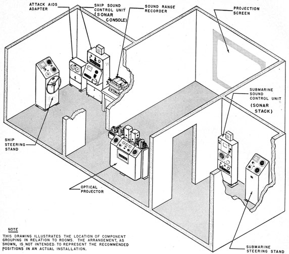
As shown in figure 17-1, the QFA-6 equipment
consists of an optical projector, a ship steering
stand, a ship sonar console, a sound-range recorder,
a submarine steering stand, a submarine sonar
stack, a screen, and an attack-aids adapter. The
screen corresponds to a miniature ocean, on which
are projected miniature images of a ship and a submarine. These images can be maneuvered independently by remote control from the steering
stands. The submarine image can be maneuvered
also by controls on the projector. The ship image,
however, must be maneuvered from the ship steering
stand. The ship steering stand and sonar console, which are functional counterparts of real
equipment, are placed in another room so that the
trainee can train his sonar beam, can hear the sonar
echo, and can maneuver his ship without seeing the
problem on the screen.
The projector contains projecting systems,
sound-effect circuits, and submarine-maneuvering
controls. The projecting systems project the ship
and submarine images, the sweeping sound beam,
and a true-bearing line. The sweeping sound
beam is a band of light that moves away from the
ship and simulates the active area of a real sonar
transmission. The true-bearing line is a line that
originates at the submarine and is manually
pointed to the ship at all times by an operator
stationed at the projector. The line is needed in
the simulation of BDI, RLI, and pattern directivity. The sound-effect circuits simulate the
acoustics of a real situation. These circuits
simulate target echo, reverberation echoes,
and transmission-signal and water noise. The
ship's propeller sounds originate in the submarine
sonar stack and steering stand. The submarine-propeller sound originates in the sonar console.
The ship steering stand and sonar console are in
a ship-control room out of sight of the projector
and are operated by a team of trainees. The team
in the ship-control room consists of a conning officer, sonarman, tactical range-recorder operator,
and helmsman. The sonar console is a counterpart of a real console and has a BDI display that
indicates in accordance with the situation portrayed on the ocean. The attack teacher can be
operated by one trainee team in the ship-control
room and one man at the optical projector. The
man at the optical projector resets the problem,
maneuvers the submarine, and keeps the true-bearing line pointed at the ship. The attack
teacher also can be operated with the submarine
steering stand and submarine sonar stack in a
separate room with a submarine trainee team.
This team then maneuvers the submarine out of
sight of both ocean screen and ship stand. An
optical-projector man is always required for operating the true-bearing line.
The attack-aids adapter is a unit that simulates
the functions of the dead-reckoning analyzer
(DRA). When a dead-reckoning tracer (DRT)
and an attack plotter (AP) are used in a simulated
CIC the attack-aids adapter provides the signals
to the tracer and the plotter. The adapter (1)
receives ship's-heading and ship's-speed signals
from the steering stands, (2) extracts the east-west (E-W) and north-south (N-S) components of
motion, and (3) develops step-motor signals for
driving the DRT and AP.
The antisubmarine-warfare situation is made as
real as possible for the sonar operator and
303
Figure 17-1 -Components of the QFA-6 attack teacher.
prospective conning officer. The images move in accordance with orders from the control equipment.
Control-equipment orders are fed manually into
the attack teacher by counterparts of real equipment-the sonar console and the ship's helm and
engine telegraph. Although the acoustic sounds
are simulated by thyratrons, oscillators, interrupted light beams, variacs, watt-hour meter
motors, and photoelectric detectors, the sonar console and stack are functionally precise counterparts of sea-going equipment. The attack teacher
thus trains officers and operators in the technique
of antisubmarine warfare. The operation of the
equipment reduces to two fundamental problems
in synthesis-(1) control of image motion in accordance with control-equipment orders, and (2)
simulation of the acoustics of a real situation.
IMAGES AND THEIR MOTION
The "Ocean"
The "ocean" of the attack teacher is a 50-inch
square screen onto which the images representing
the submarine and the ship are projected from the
optical projector. The screen represents a square
section of ocean, the top being north and the right
304
side being east. The images of the vessels are
boat-shaped objects, which rotate as the vessels
change heading, thereby indicating to an observer
at the projector the direction of vessels' motion.
The scale of the ocean varies from 40 to about 170
yards per inch, depending on the projection
distance.
An operator stationed behind the screen can
plot the positions of the images with grease
pencils, thus providing a plot of the courses of the
vessels depicted.
Optical System
Two completely independent optical systems
produce ship and submarine images. The ship
image originates in a projecting system at the
right of the projector, the optical axis of the system being parallel to the screen. The light from
this projector is deflected vertically by a rotatable
first surface mirror, which has its axis of spin
perpendicular to the plane of the screen. A second
rotatable first surface mirror, arranged to receive
the light from the first mirror, has its axis of spin
parallel to the plane of the screen and diverts to
the screen the light that is incident upon it. The
result of this combination is that (1) rotation of
the first mirror produces lateral, or east-west, motion of the image on the screen and (2) rotation
of the second mirror produces vertical, or north-south, motion on the screen. Rotation of the
mirrors in accordance with the north-south and
east-west components of the velocity of the ship
results in motion of the ship image on the screen.
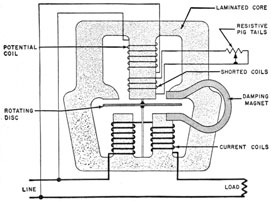
Figure 17-2 -Schematic diagram of a single-phase watt-hour
meter motor.
The submarine image is projected onto the
screen in an identical manner. This image originates in the optical system at the left of the projector. Both ship and submarine images can be
moved to any point within the confines of the
screen. The two images can be differentiated by
color and by length, the ship image being green
and approximately 120 scale-yards long and the
submarine image red and 80 scale-yards long.
The motion of the projecting mirrors is controlled by driving each mirror through gears with
a specialized type of induction motor, which is
closely related in design and performance to the
conventional a-c watt-hour meter motor. Because
watt-hour meter motors are used throughout the
attack teacher, a working knowledge of the induction watt-hour meter motor is essential for understanding the speed and direction controls of the
ship and submarine images.
Watt-Hour Meter Motor
The watt-hour meter motor functions as a split-phase induction motor. It consists of an electromagnet, a rotating element, and associated damping
magnets. The electromagnet is composed of
a potential coil and two current coils. As the
names imply, the potential coil is across the line
and the current coils are in series with the line
(figure 17-2).
The coils are mounted on a common laminated
iron core. Their physical relationship is shown
in figure 17-2. An aluminum disk is mounted
between the potential and current coils on a vertical shaft set in jeweled bearings. This disk is the
rotating element.
Because the current coils are in series with the
line and carry the load current, they are wound
with a few turns of heavy wire. The load current
through these coils produces a flux that is proportional to and in phase with the line current.
The potential coil is a high-impedance winding
composed of a great many turns of fine wire. The
current through this coil is nearly 90° out of phase
with the applied potential. However, the currents
in the potential and current coils must be in exact
quadrature if the speed of the motor is to be proportional to the power factor. To shift the flux
of the potential coil so that it is exactly 90° from
the flux of the current coils, a small coil, short-circuited through resistance-wire pigtails, is placed
in the flux path of the potential coil. The current
305
induced in the shorted coil constitutes a magnetomotive force which combines with that of the
potential coil to produce the potential coil flux.
By adding the proper amount of resistance to the
coil by means of the resistive pigtails, the flux from
the potential coil can be made exactly 90° from
that of the current coils.
These two quadratured flux components induce
eddy currents in the portion of the disk that is in
their respective field. The interaction of the eddy
currents in the disk and the field across the disk
causes the disk to rotate. The direction of rotation is controlled by the polarity relation of the
potential and current coils. Reversing the connections of the potential coil reverses the direction
of rotation.
When the motor is operating properly, the
torque on the disk is zero for a zero power factor
load and greatest for a unity power factor load.
For a given set of values of voltage, E, and current,
I, the torque is proportional to the load power
factor, cos θ. To calibrate the mechanical output
of the motor and to make the motor speed constant
for given values of EI cos θ, damping magnets are
mounted so that the disk cuts their magnetic field.
The eddy currents thus induced tend to oppose the
rotation of the disk. The damping action is
proportional to the speed of the disk-it is small
when the disk rotates slowly and large when it
rotates rapidly. For any given load the driving
torque causing the disk to rotate is balanced by
the damping action of the drag magnets and the
speed is constant. The rotational speed is proportional to EI cos θ. Because EI cos θ is the true
average power of the electric circuit, the speed of
the disk is a measure of the power being supplied
to the circuit.
Mirror-Drive Motors
In the attack teacher one mirror reproduces
north-south motion of a vessel and another mirror
reproduces east-west motion. Because a watt-hour meter motor moves its rotating disk at a
speed proportional to EI cos θ, one meter motor
can be used to extract the north-south component
of vessel motion by energizing (1) the current coil
of the meter motor with a current proportional to
ship speed, and (2) the potential coil with a current proportional to cos θ1, where θ1 represents
the heading away from north. Similarly, a second
meter motor can be made to rotate in accordance
with the east-west component of vessel motion
when (1) its current coil is energized with current
proportional to vessel speed and (2) its potential
coil is energized with a signal proportional to
cos θ2, where θ2 represents heading away from the
east. Because θ1 and θ2 are 90° apart, cos θ2
equals sin θ1.
The attack teacher uses two watt-hour meter
motors, called coordinate motors, to reproduce the
motion of each vessel. The current coils of the
motors are in series and are energized by the same
current, which is proportional to ship speed. The
potential coil of one motor is energized by a signal
proportional to cos θ; the potential coil of the
other motor is energized by a signal proportional
to sin θ, where θ equals the heading of the ship.
Figure 17-3 shows the schematic diagram of the
speed and direction controls of the attack teacher.
It shows (1) the circuits of the ship controls in the
ship steering stand and (2) the circuits of the submarine controls in the optical projector.
N-S and E-W coordinate motors, K1401 and
K1402, are single-phase watt-hour meter motors.
The current circuits of the E-W and the N-S
mirror-drive motors of the ship projection system
are in series. The current in these circuits is
varied so as to be proportional to the speed of the
ship. Thus, the current coils of both coordinate
motors receive the same current, which is proportional to ship speed.
The potential circuits of the motors are excited
from the secondary of a two-phase phase-shifting
transformer, which is positioned as ship's heading.
The primary of the transformer is excited from a
two-phase generator that is provided with the
equipment. The phase-shifting transformer has
a rotor similar to that of a two-phase wire wound
induction motor rotor and may be rotated to any
angular position. As the rotor is shifted the phase
angle between secondary and primary voltages is
shifted uniformly.
The phase angle of the common current in the
current circuit of the coordinate motors is constant with respect to the primary excitation of the
phase-shifting transformer. If the phase angle of
N-S motor potential with respect to this current is the angle 0, and if the output potential of
the phase-shifting transformer is constant, the
resultant torque of the N-S element, LN-S, may be
expressed as follows:
LN-S=k1I cos θ.
The potential on the east-west element is advanced
90° electrically in phase, and the torque of this
element, LE-W, may be expressed as follows:
LE-W = k1I cos (θ-90°) = k1I sin θ.
Thus, the coordinate motors move at a speed proportional to the E-W and N-S components of the
motion of the vessel.
Both mirror motors are equipped with conventional watt-hour-meter motor-damping magnets of
such strength that the rotor speed is directly
proportional to the torque if the mechanical load
on the motor is negligible or compensated for. As
previously defined, the current in the motor
elements is proportional to the speed of the ship.
The equations of torque therefore reduce to the
following:
N-S speed= ship speed X cos θ,
E-W speed= ship speed X sin θ.
If by calibration, θ is made the true-compass
course of the ship, and if ship's heading is maintained thereafter as the angular position of the
rotor of the phase-shifting transformer, the mirror
speeds are as follows:
The N-S mirror speed is proportional to ship
speed times the cosine of ship's heading, and the
E-W mirror speed is proportional to ship speed
times the sine of ship's heading. An identical
analysis is applicable to the motion of the submarine.
Tactical Considerations
The control of the motion of the ship and the
submarine reduces to control of (1) the angular
position of the rotor of the phase-shifting transformers, and (2) the proper variation of the current
in the current circuits of the mirror motors.
These variables are representative of the direction
and speed of the vessel depicted. It is necessary
that the tactical characteristics of the vessels
represented be as close as possible to the characteristics of real vessels.
One characteristic of a given class of vessels is
that the turning circle for any given rudder angle
is nearly independent of speed. This characteristic exists because there is little sideway slippage
when a ship is in a turn. Therefore, the rate of
change of ship's heading for any given rudder
angle must be directly proportional to the speed of
the ship. This tactical consideration is injected
into the attack teacher by making the rate of
turning of the rotor of the ship's-heading phase
shifter proportional to the current in the mirror-motor circuits.
Other tactical considerations are (1) the acceleration or deceleration delay, which accounts for
the time necessary to get a ship to the desired
speed, (2) the turning delay, which accounts for
the advance (the distance traveled before the
rudder takes effect) and the transfer (the additional
distances necessary to enter a constant turning
circle), and (3) the loss of speed in a turn. These
considerations are injected into the attack teacher
by controlling the response of (1) the rudder
motor-a watt-hour meter motor that drives the
rotor of the phase shifter-and (2) the current in
the current coils of the coordinate motor. The
ship rudder motor, B705, is shown at the left of
figure 17-3. The submarine rudder motor, B210,
is shown at the lower right of figure 17-3.
The ship steering stand has counterparts of an
engine-room telegraph and a speed indicator. As
shown in figure 17-3, these units control variacs
and watt-hour meter motors, which in turn control
the response of the rudder motor and coordinate
motors. The rudder-motor positions the rotor of
the ship's-heading phase shifter, which in turn
determines the position of the image on the screen.
The current in the current coils of the coordinate
motors determines the speed of image motion.
The engine telegraph operates a ship-speed control through a time-delay circuit, which provides
acceleration rates typical of the class of ship
depicted. The helmsman's wheel on the steering
stand actuates another time-delay circuit, which
provides rudder delays. This circuit uses the
turning-delay variac. The turning-delay variac
and rudder variac, which operate the rudder
motor, are energized by the engine-telegraph variac
so that the turning rate is proportional to
ship speed. Therefore, the turning circle of the
ship is constant at all speeds below 20 knots-as
it should be. Above 20 knots, however, the turning
circle increases with speed because the watt-hour meter motors cannot be controlled over so
wide a range of speeds.
307
The loss of speed in a turn is provided for in the
rudder-control mechanism by the operation of the
speed-decay variac, T705. This variac causes the
ship image to slow down when in a turn with 15°
or more of rudder angle. The rate of deceleration
is determined by the speed-control unit, consisting
of a speed-control variac and a speed-control
motor. The final value of speed in a turn is
determined by an adjustment in the steering stand.
A gyrocompass repeater card, which is attached to
the end of the rotor of the phase-shifting transformer, indicates the ship's heading.
The controls for the speed and turning of the
submarine image are fundamentally identical
with those for the ship image. In normal use, the
submarine image is controlled from a steering
stand, which is almost identical with that provided
for the ship image. As has been mentioned, control of the submarine image is available also at the
projector. The fundamental control principles
for the submarine image are identical with those
for the ship image except that the turning circle
of the submarine image is constant at speeds up
to 12 ½ knots and increases in proportion to the
speed above 12 ½ knots.
The value of the attack teacher for teaching
under-way control of vessels is increased by providing for the simulation of the tactical characteristics of many classes of vessels. The variable-speed motors of the rudder- and speed-control
circuits can be adjusted over a wide range of
speeds. It is possible, therefore, to adjust the
equipment to the exact characteristics of any class
of vessel by a suitable combination of turning
delay, turning rate, acceleration characteristics,
and speed loss in a turn. As new surface and
underwater vessels are developed and the tactical
characteristics are made available, attack teachers
must be calibrated accordingly. Therefore, the
personnel who maintain attack teachers must
understand thoroughly the basic principles and
adjustments that determine the tactical characteristics of both the ship and the submarine.
Although the attack teacher is primarily a sonar
training equipment, the realism of ship response
to the helm and engine-telegraph orders makes the
attack teacher useful for under-way ship-handling
problems. For instance, it may be used for
station-keeping and station-changing problems by
using (1) the submarine image as the guide vessel
and (2) the sound information as radar range and
bearing. This important function should not be
neglected by training activities.
SIMULATING THE SONAR SOUND BEAM
In a real situation, the sonar operator aboard
ship trains his sonar beam to obtain the range and
bearing of the target. Because the images on the
attack-teacher screen do not have transducers, it
is necessary to simulate the sonar beam and the
directional pattern of the beam.
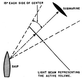
Active Area
In addition to the ship and submarine images
and the true bearing line a fourth image on the
ocean screen represents the active area of the
echo-ranging sound beam. The ship projecting
system is equipped with a second optical system,
which projects a band of light onto the screen
(figure 17-4). The band of light periodically
travels away from the ship across the screen at a
speed equal to one-half the scale velocity of sound
in water. This speed makes the band represent
the active area of a real sound beam. The
direction of motion away from the ship is controlled by a training mechanism on the sonar
console. The zero, or pivoting, point of the beam
is coincident with the image of the ship, irrespective of the position of the ship on the screen.
The two images optically converge upon each
other at the screen and move over the screen
together by the rotation of their common mirror
system. The traverse of the beam from the zero
position is initiated by the keying of the sound
equipment. Although all the projected beams
originate in d-c excited lamps so that there is no
60-cps modulation of the beams, the light beam
that simulates the sound beam is interrupted so
that it can be detected electronically.
The submarine projection system has a telescope
that is trained on the submarine image through a
common mirror system. At the focal point of this
telescope is an orifice, which permits only light
that is incident on the submarine image to pass
through it. An extremely sensitive phototube
coupled to a suitable amplifier is placed beyond
the orifice of the telescope. A simulated echo
signal is produced by the phototube when the
sweeping sound beam passes over the submarine.
The "echo" amplifier is sensitive only to a-c signals
308
from the phototube. Therefore, the amplifier is
insensitive to the light from the submarine image-which is derived from a d-c source-and responds
only to the "a-c" sound beam.
In a real sonar equipment, an ultrasonic wave
is transmitted and the resulting ultrasonic echo is
heterodyned to an audio frequency. In the attack
teacher ultrasonic frequencies are not used. The
d-c-excited source that develops the active area
of the searching sound beam is interrupted at an
audio frequency so that the output of the photo-electric detector (corresponding to the echo signal)
is an audio signal (corresponding to the audio
output of the sonar receiver).
The sound-beam projection system is equipped
with a motor-driven disk with peripheral holes,
which interrupt the d-c-excited light at a frequency
of 800 cycles per second ± doppler. Therefore,
if the sound-beam image crosses the submarine
image in its transit across the screen an a-c signal of
the frequency of the pulsating light is delivered to
the amplifier by the phototube. This amplifier
transmits the signal to the sonar console, where
it may be both heard over the loudspeaker and
seen on the range-recorder trace. The sound beam
moves away from the ship at half the scale velocity
of sound, and the 800-cps tone is heard the instant
the beam reaches the submarine. The elapsed
time is the same as if the beam traveled at the
Figure 17-4 -Projected band of light that simulates the active
area of the sound beam.
scale velocity of sound and were reflected from
the submarine back to the ship before being
detected. Therefore, the range-indicating or
recording equipment indicates the true-scale
range. The bearing of the target is determined
by the rotatable angular position of the axis of
the sound beam. The bearing is indicated by
conventional bearing repeaters.
Slant Range
In echo ranging, recorded or indicated range is
complicated because the target usually is below
the surface of the ocean. Therefore, measured
range in a real sonar is the slant range or distance
to the target. The range across the surface of the
ocean to a point directly above the target is defined
as the horizontal range. Most of the interpretive
devices employed in attack procedures assume
that the recorded or indicated range is identical
with the horizontal range. With very deep targets, a substantial error is introduced by the discrepancy between slant and horizontal range
because the discrepancy increases as the attacking
ship moves close to the target. This practical
difficulty has led to the inclusion in the attack
teacher of a means for producing the slant-range
effect. The sound-beam projecting device can be
modified to provide simulation of the slant-range
effect for any desired target depth. This modification is accomplished by substituting a cam in
the projecting mechanism. Five arbitrary target
depths are provided-0, 100, 200, 300, and 400
yards. A different cam must be substituted for
each depth.
Sound-Beam Training Control
The sound-beam training-control circuit can be
operated manually or by either or both of two
additional control circuits-(1) maintenance of
true bearing (MTB), which maintains the sound
beam on a constant true bearing regardless of
changes in the vessel's heading, and (2) automatic
search, which provides variable search programs
without operator control.
The maintenance-of-true-bearing circuits are the
same in principle and in function as those of
standard equipment. A switch representing a
battle-damage switch provides for relative-bearing
training procedures.
The automatic-search provisions in this equipment depart from existing standard equipment in
309
that the continuous-rotation principle is employed.
A mechanism is provided whereby the true bearing
of the sound beam is changed continuously at
three discretionary speeds. The sonar equipment
is keyed at each 5° of train, thus providing a search
pattern of 5° regardless of the keying interval. In
other words, the keying interval is fixed by the
rate of rotation of the sound beam.
The bearing indicator associated with the
training-control unit is entirely different from that
of standard equipment. The conventional azimuth ring, rotating lubber line, and inner compass
card are replaced by (1) an edgewise card indicating
true bearing and (2) a small relative-bearing
indicator, which may be read only to within 5°.
The QFA-6 uses a beam that starts at the ship.
Therefore, only the ship station has simulated
sound-ranging equipment. Range information is
provided to the submarine station by using the
ship returns, as will be explained later.
SIMULATING RLI AND BDI
A real ship has BDI circuits and a real submarine
has RLI circuits for obtaining accurate bearings.
These circuits make use of the directivity of split
transducers and hydrophones. Because the attack
teacher does not have split hydrophones or transducers, it is necessary to simulate them. They
are simulated by use of a position keeper operated
by the optical-projector operator.
The position keeper controls the position of the
true-bearing line, which is projected onto the
screen. The submarine, or left-hand projector,
system has an element that projects the line image
onto the screen. This line always begins at the
submarine because of the common mirror system.
The line is approximately 2,500 scale-yards long,
and it is radial to the center of the submarine. It
can be rotated through 360° and is graduated in
500-yard steps, with range marks at 500, 1,000,
1,500, and 2,000 yards. The image-forming reticle is rotated by a synchro motor, which receives
its orders from a synchro transmitter that is manually rotated by the operator. The projector
operator's task is to manipulate the handwheel on
the transmitter so that the beam of light at all
times points directly to the pivoting point or center
of the ship image on the screen. A synchro
system is thus available in the equipment whereby
the true bearing of the ship from the submarine
(or of the submarine from the ship) is available
for control purposes.
The true-bearing line is maintained in proper
position-that is, pointing from the submarine
image to the ship image-by the optical-projector
operator. The bearing of the true-bearing line
determines the position of (1) a vane in front of a
photoelectric detector, and (2) a rotor of a phase
shifter, called a signal splitter. Whenever the
sound beam falls exactly on the true-bearing line,
the signal splitter sends a no-deviation signal to
the BDI. When the sound beam is to the right
or left of the true-bearing line, the signal splitter
sends an appropriate right or left signal to the
BDI indicator. Thus, the true-bearing line serves
as a reference axis for the BDI circuits. The true-bearing line is used in a similar way for simulating
RLI circuits.
The vane in front of the photoelectric detector
is used with the true-bearing line in simulating
listening-pattern directivity. When the axis of
the simulated listening pattern is not exactly on
the true-bearing line, the vane moves and the
photoelectric detector develops a signal. This
signal is used to vary the gain of an amplifier so
that when the axis is off the beam, the intensity of
the audio output is reduced.
Figure 17-5 shows the schematic diagram of the
receiver-amplifier and BDI circuits used in the
ship station. The target true-bearing repeater,
B805, shown at the upper right corner of figure
17-5, receives its signals from the true-bearing-line
transmitter at the optical projector. Its output
drives one side of a mechanical differential. The
other side of the differential is driven by the output of another differential, which is driven by
both a ship's-compass repeater and a sound-beam
relative-bearing repeater. Thus, the output of
the second (upper) differential is the true bearing
of the sound beam, and the output of the first
(lower) differential is the bearing-angle off-train,
as represented by the true-bearing line. The
angle off-train output is coupled mechanically to
the rotor of the signal splitter.
The stator of the signal splitter is energized
by the echo signal. The magnitude of the two
outputs of the rotor of the signal splitter depends
on the angular position of the rotor with respect to
the stators. This position in turn depends on the
angle off-train of the sound beam. The outputs
are amplified in a twin-channel amplifier and then
applied to the comparison rectifier, V831. The
two diodes of the rectifier can conduct simultaneously, but the polarity of the output of the comparison rectifier depends on which diode receives
the bigger signal. The d-c output of the comparison rectifier is amplified in a d-c amplifier and is
applied to the horizontal-deflection coils of an
oscilloscope indicator. The bearing-deviation indication is simply right or left motion of the
oscilloscope spot.
The RLI circuits for the submarine station function like the BDI circuits just described for the
ship station. When the hydrophone is trained so
that its beam axis is not exactly on the true-bearing
line, the angle off-train of the simulated submarine hydrophone is used to position a signal
splitter similar to the one just described. The
stator of the signal splitter is energized by the
signal that simulates ship-propeller sounds. The
outputs of the phase splitter are rectified by a
twin diode and are used to energize a meter movement.
The projector operator who manipulates the
true-bearing line thus functions as a position
keeper-that is, he is responsible for indicating at
all times the relative position of the two vessels.
The angle off-train of the simulated sound beam
(or the simulated hydrophone) from the true-bearing line energizes the BDI and RM circuits.
SIMULATING ACOUSTICS
Forming the Beam Pattern
In a real sonar, the operator sometimes uses the
transducer as a hydrophone to listen for sound
emitted from the target. The transducer beam
pattern gives him directivity in his listening. To
simulate this situation in the attack teacher, a
special device is needed to sharpen the pattern for
listening, because the BDI simulator does not use
a real transducer. The pattern is sharpened by a
photoelectric cell, V858, and a vane attached to
the differential output of angle off- train (figure
17-5), as referred to the bearing of the true-bearing
line.
The submarine propeller sounds are simulated
in the submarine propeller-noise modulator in the
ship sonar console. The modulator uses a variable-
speed rotating carbon disk to make noises like a
propeller. The output of the propeller-noise
modulator is fed to a range attenuator, which
governs the amplitude of the propeller noise as a
function of range to the target. The output of
the range attenuator is fed to the grid of the audio
amplifier, V842, which is used as a gate tube.
The amplification of V842 depends on a bias
developed by the photoelectric cell, V858. The
vane in front of the photocell is positioned by
angle off-train. As the vane moves, it causes
light from the d-c-excited light to fall onto the
photoelectric cell. The voltage developed by the
cell is applied as a bias to the grid of one section of
V843, which is used as a d-c amplifier. The d-c
amplifier is operated with the plate near ground
potential and the cathode and grid returned to
the o275 volt line. The output of the d-c amplifier is used to control the bias and gain of V842.
Thus, as the sonar operator trains the transducer
axis away from the true-bearing line, the vane
controls the gain of the audio amplifier and produces a directional-pattern effect. The shape of
the vane affects the "beam pattern."
Submarine Listening Equipment
The submarine sonar stack has a pattern-simulating circuit similar to that in the ship sonar
console. The ship's propeller sounds, which are
simulated in the submarine stack, are fed to an
audio amplifier, the gain of which is controlled by
a vane in front of a photoelectric cell. The position
of the vane is controlled by the angle off-train of the
listening hydrophone. Thus, as the operator
trains his "hydrophone" off the true-bearing line,
the audio output of the amplifier is reduced.
Echo Frequency
The echo frequency is determined by interrupting the d-c excited light beam that produces
the active area. In the attack teacher this frequency is 800 cycles per second ± doppler shift.
The beam is interrupted by a chopper disk
attached to motor B206 (figure 17-3), which is a
split-phase induction motor. This motor is driven
by the motor amplifier. The signal input to the
amplifier originates in another photoelectric detector, V203 and V204. The light falling on the
photocells is interrupted by a disk attached to the
echo motor, B221, which is a polyphase watt-hour
meter motor. The speed of this motor is controlled
311
by the following factors: (1) The basic 800-cps
frequency, (2) the speed and heading of the ship,
(3) the speed and heading of the submarine, and
(4) the relative bearing of the sound beam. The
first factor is the basic audio frequency if no doppler is present. The second and third factors control the doppler shift that must be imposed on the
echo frequency. The second and fourth factors
control the doppler shift that must be imposed on
reverberation echoes.
The basic 800-cps frequency is set by the beat-frequency-oscillator (BFO) control. This control is
simply a variac which simulates the function of the
BFO in a real sonar. The variac, T816, is shown
at the lower left corner of figure 17-3. It controls
the current through one of the current coils of the
echo motor B221. The currents through the other
current coils come from (1) the ship's coordinate-motor current coils, B213 and B214, and (2) the
submarine's coordinate-motor current coils, B215
and B216.
The potential coils of B221 are energized from
the phase-shifters, B806 and B203, which establish
the relative motion of the two ships along the
bearing line joining them. All these inputs combine to make the watt-hour meter motor, B221,
rotate at the proper speed so that the light beam
that falls on V203 and V204 is interrupted at 800
cps ± doppler.
The motor drives a disk, which chops the light
that falls on photoelectric cells V203 and V204.
The output of the photoelectric cells is amplified
in the two-phase push-pull motor amplifier and is
used to drive the chopper-disk motor, B206. This
motor is specially designed to follow rapidly all
changes in excitation frequency. It carries the
chopper, which interrupts the beam that develops
the active area. Thus, the frequency of the modulation imposed on the beam is 800 cps ± doppler.
Reverberation
The attack teacher simulates the reverberation
echoes heard immediately after each transmission.
Own ship's doppler, which depends on own ship's
speed and relative train of the sound beam, must
be imposed on the reverberation echoes. The
reverberations are developed in the ship sound-effect circuits, which are not illustrated schematically. These noises are developed by a thyraton
and an 8.5-kc oscillator. The reverberation meter
motor, B220, shown in figure 17-3 functions like
the echo meter motor, B221, described previously.
B220 has a disk, which interrupts the light that
falls on photocell V202. The speed of B221
depends on ship speed and the relative bearing of
the sound beam. Thus, the output of V202 is
the audio frequency of own ship's doppler, which
is modulated upon the reverberation noises developed in the ship sound-effect circuits. The
ship sound-effect circuits also develop noises to
simulate water noise and transmission-signal
noise.
Range Attenuator
The intensity of the sounds heard at both ship
and submarine should change as the range between
ship and submarine changes. The attack teacher
has a range attenuator that performs this function.
A control box on the projector contains a transmitter that rotates the true-bearing line. This
control box contains a potentiometer with a dial
calibrated in yards of range. The operator positions the potentiometer by estimating the range of
the ship image from the submarine image. He
uses the graduations on the true-bearing line to
estimate the range. This rough estimate is sufficient for attenuation.
The potentiometer applies potential to two
diodes, one in the acoustic amplifier of the submarine stack and the other in the acoustic amplifier
of the sonar console. These diodes control the
screen potentials, and hence the gain, of a stage
in the acoustic amplifiers. Thus, as range changes,
both the intensity of the ship-propeller sounds
heard at the submarine stack and the intensity of
the submarine-propeller sounds heard at the sonar
console change.
Magnitude of the Doppler Effect
In the ocean the frequency of the sonar echo is
affected by the motion of both the ship and the
target because of Doppler effect. The frequency
of the "echo" in the QFA attack teacher is the
modulation of a projected light beam, which is
interrupted by a chopper. The frequency of the
modulation of the beam is varied in accordance
with the motion of both ship and target by
varying the speed of the motor that rotates the
chopper. This motor is controlled by own ship's
motion, target motion, and sound-beam bearing.
312
First consider the magnitude of the Doppler
effect on a real ocean. The exact expression for
the echo frequency is:
FE=Fo(1+ 2V1/v cos θ - 2V2/v cos α),
where FE is the echo frequency, Fo the transmission
frequency, v the velocity of sound in water, V1 the
speed of own ship, V2 the speed of the submarine,
θ the relative bearing of the transducer on own
ship, and a the angular difference between the
submarine heading and true sound bearing.
When the echo is heterodyned in the receiver
with a beat-frequency oscillator of frequency FH,
the output audio frequency, fE, is
fE=FE-FH
fE=Fo-FH+(2FoV1cosθ)/v - (2FoV2cosα)/v.
The expression "Fo-FH" is the audio frequency
of the echo if neither ship nor target is moving.
It is also the reverberation frequency if the ship is
not moving. If the term "Fo-FH" is represented
by fo then
fE=fo+(2FoV1cosθ)/v - (2FoV2cosα)/v
Note that the second term represents the ship's
motion. Therefore, the term,
(2FoV1 cos θ) / v,
can be defined as own ship's doppler (OD).
Similarly, the third term,
(2FoV2 cos α) / v,
represents the effect of target motion only and is
called target doppler, or TD.
Therefore, the audio echo frequency after heterodyning is
fE=fo+OD-TD.
The reverberation returns depend only on own
ship's motion, and the audio frequency of the
reverberation returns is given by the first two
terms in the previous equation-that is,
fo+OD.
In the attack teacher, the frequency fo is
developed by chopping the light beam. The reverberation frequency is obtained by adding OD
to fo. The simulated echo frequency is obtained
by adding OD and TD to fo.
Maximum doppler effect equals 2Fo/v times the
relative velocity of the vessels. Assume that Fo,
is 20,000 cycles per second and that v is 1,600 yards
per second. If the velocity of the vessel is expressed in knots, v also must be expressed in knots.
Because 1 knot is 2,000 yards per hour, it is
2,000/3,600,
or 0.555, yard per second. Therefore,
2Fo/v = 2(20,000)(0.555) / 1,600 = 13.9.
The expression for audio echo frequency then
becomes
FE = fo+ 13.9 (V1 cos θ - V2 cos α) cycles per second.
With present-day speeds of ships, the doppler
shift can change an 800-cps basic tone as much
as 600 cycles per second-that is, from 200 to
1,400 cycles per second. In the attack teacher,
therefore, the meter motors are designed to change
the modulation of the sound beam and the frequency of reverberation noises between the limits
of 200 and 1,400 cycles per second.
Doppler Nullifiers
In real equipment, nullifier circuits are added to
the listening channels to compensate for own ship's
doppler and target doppler. The own ship's
doppler nullifier in a real sonar uses information
from both own ship's speed and transducer heading in order to change the frequency of the beat-frequency oscillator and return the audio output
to 800 cycles per second. Similarly, the target-doppler nullifier in a real sonar samples the first
few cycles of the echo in order to correct the frequency of the beat-frequency oscillator to 800
cycles per second. Doppler nullifiers are not provided in the attack teacher, although nullifying
can be done simply by not imposing ship's motion
on the reverberation meter motor that establishes
the basic 800-cps modulation.
Submarine Sonar Stack
The submarine sonar stack (figure 17-1) is-simpler than the ship sonar console. It includes
an indicating range recorder, a remote training
and bearing unit, and a receiver-amplifier with a
separate loudspeaker.
The attack teacher projects the echo-ranging
sound beam from the ship only. Thus, certain
313
assumptions must be made in order to supply
range information to the submarine without duplicating the echo-ranging devices. These assumptions are (1) that the submarine does not attempt to
obtain the range of the ship until it has definitely
established the ship's bearing by means of its
listening equipment, and (2) that echo ranging is
not continuous but is limited to the emission of
infrequent single signals.
If a submarine and a ship were echo ranging
simultaneously on each other, both vessels would
hear (1) a transmission signal, (2) reverberation,
(3) water noise, and finally (4) an echo. The time
interval between the transmission and the echo
would be the same for each vessel, but the frequencies of all the returns would be different
because of the different doppler changes. The
attack teacher uses the returns received at the
ship sonar console in the submarine sonar stack
to keep from duplicating the echo-ranging facilities.
These returns give correct range but incorrect
acoustic frequencies at the submarine station.
To include the single-ping feature in the submarine station, the input of the submarine sonar
receiver of the attack teacher may be from one of
two sources and is selected by a two-position
switch. The switch positions are marked "echo
range" and "listen." In the echo-range position
the input of the submarine receiver is paralleled
with the input of the ship receiver, and the input
stage of the submarine receiver is made insensitive
until the equipment is keyed. The keying pulse
originates in the keying-control circuit of the ship
and is the same pulse that initiates the cycle of
events for the echo-ranging synthesis of the ship.
Thus, both ship and submarine circuits are keyed
simultaneously. The action of the keying pulse
in submarine circuits is (1) to increase to normal
the sensitivity of the input stage of the receiver,
(2) to start the stylus drive circuit of the indicating-range recorder, and (3) to fire a keying lock-out
thyratron. Therefore, as long as the ship has
sound contact, the echo from this transmission is
available also to the submarine equipment, which
prints on the indicating-range recorder at the
proper range. However, the frequencies of the
reverberations and echo are incorrect, and the
possibility of obtaining an echo has nothing to do
with the bearing of the submarine hydrophone.
Once the keying lock-out thyratron fires, any
further keying pulse cannot actuate the keying
circuits until the thyratron is deionized by changing the selector switch from echo range to listen.
At the end of the keying cycle-that is, when
fly-back occurs-the input stage of the receiver
becomes insensitive again and remains so until (1)
the keying circuits are recycled by the selector
switch, and (2) a new keying pulse again initiates
a keying cycle. This arrangement provides the
submarine sonar stack with echo-ranging facilities
without duplicating the echo-ranging facilities of
the ship.
No-Doppler Target
For some training operations, it is desirable to
have a means of injecting a no-doppler target-that is, a target with no Doppler shift in frequency.
Such a target can be used to train sound operators
in identifying actual targets by the presence or
absence of Doppler effect. It can be used also to
produce an approximation of a wake echo. An
accessory projecting device is mounted at the left
end of the optical projector. It consists of (1) an
image projector, which provides a red circular
image on the screen, and (2) a telescope with a
large objective, which is trained upon this image.
Adjustments are available for positioning this
image to any portion of the ocean screen. The
combination is similar to the arrangement of the
submarine projector except that in the accessory
projecting device, the image is not motor-driven.
A photocell is located beyond the orifice of the
telescope and is coupled to an amplifier. The
electric signal produced when the sonar sound-beam traverses this image has a frequency that is
correct for an echo from the attack-teacher submarine but that is incorrect for an echo from a
no-doppler target. Therefore, this signal is rectified and used to key the reverberation oscillator,
the output of which is used as the no-doppler
target echo. The reverberation oscillator is keyed
for an interval of time equal to the time for the
sound beam to sweep across the no-doppler target.
The no-doppler target therefore (1) has its own
correct range and bearing indicated and (2) has a
frequency that includes own ship's doppler but
not target doppler.
314
AN/UQS-TI Sonar Training Set
DESCRIPTION
The AN/UQS-T1 sonar training set, or trainer,
is a sonar problem generator that furnishes two
or more synthetic sonar targets, in the form of
artificial echoes, to a standard pulse-type scanning-sonar equipment. The synthetic targets are independently maneuverable in three dimensions, and
the ship input to the trainer may be either actual
own ship's motion or synthetic own ship's motion.
Synthetic-target information is provided to all
elements of the antisubmarine installation except
the target depth-determining equipment. Control
circuits are available for attaching a target depth-determining equipment trainer in the future.
The equipment provides realistic training for all
members of the antisubmarine attack team,
whether the ship is in port, under way on a fixed
course, or engaged in attack maneuvers. The
problem generators are constructed with an accuracy sufficient for use in precise tactical evaluation.
For shore-based or tender installations, an optical projector is provided that is similar to the
projector of the model QFA-6. It projects onto
a screen the image of own ship. Motion of the
image on the screen represents the movement of
the ship in the ocean. A target image representing
the motion of the target also is projected onto
the screen. When two to four targets are used,
the coordinate motors of the projector are switched
between targets. A person can stand behind the
screen and can manually trace the path of each
target with grease pencils so that the tracks of
targets and surface ship may be plotted.
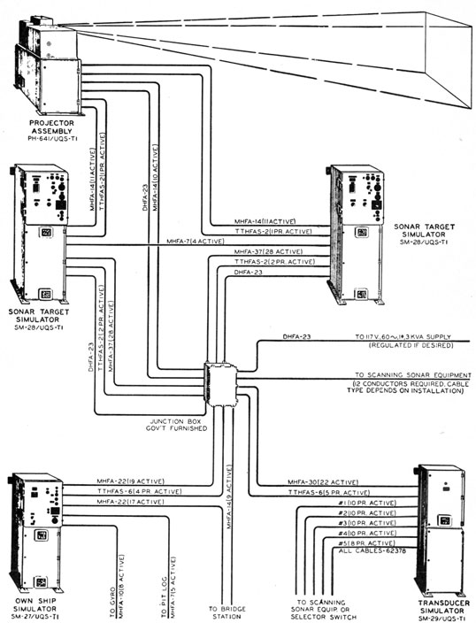
As shown in figure 17-6, the basic equipment
consists of four major units-an own ship simulator, two sonar target simulators, and a transducer
simulator. For shore-based or tender installations, a fifth major unit, an optical projector, is
supplied. For installations in which the equipment must perform with maximum accuracy, a
voltage regulator is also available.
Own Ship Simulator
The own ship simulator, as its name implies,
contains circuits that generate factors of own
ship's performance. A four-position selector
switch on the front of the cabinet determines the
mode of operation, as follows:
1. Off. When the switch is in this position all
units of the equipment are turned off. This switch
therefore acts as the main power switch for the
entire equipment.
2. Generate. With the switch in this position,
the motion of the ship is synthesized from the
engine-telegraph voltage order and the rudder-telegraph synchro orders. These speed and rudder-angle orders originate at an external source,
such as a mocked-up steering stand. Appropriate
speed delays and turning delays are introduced
automatically. The delay rates are adjustable
so as to cover various types of antisubmarine
vessels. This position is used for shore and tender
installations, as well as for ships on a fixed course
or in port.
3. Follow. With the switch in this position,
the ship image of the trainer follows the motion of
own ship, using as inputs the orders from ship's
gyro and pit log. This operating position may
be used when it is desired to maneuver an anti-submarine vessel in a simulated attack.
4. Calibrate. This position is used for testing
and calibrating the equipment. With the switch
in this position the ship responds to the direct
speed and rudder controls on the front of the
cabinet.
Sonar Target Simulator
The two sonar target simulators contain all the
circuits that generate factors of target performance. A target may be operated with a maximum
speed of 30 knots, or, if a pair of gears in the calculating system is reversed, the target may have a
maximum speed of 60 knots. Dials pertaining to
speed are labeled appropriately to indicate the
speed for which a target is set up. A submarine
target should be arranged to have a maximum
speed of 30 knots. Because accuracy of target
motion is directly proportional to the speed of the
motor drives, it is desirable to operate the drive
motors at their maximum speeds for any given
rate of target motion. Therefore, when the target
is operated at a 30-knot maximum the 2-to-1
315
Figure 17-6 -Pictorial diagram of the AN/UQS-T1 equipment.
316
step-down of the gears ensures twice the accuracy
of target motion in the lower speed range. In addition to the two speed ranges, each target operates in one of five modes selected by a single
rotary switch, as follows:
1. Normal. In this mode the target functions
as a normal submarine with all appropriate delays
in acceleration and response to the helm. By
means of adjustments, the tactical characteristics
of any type of submarine can be duplicated.
2. Reset. In this mode the target may be positioned very rapidly (in 2 or 3 seconds) to any desired range and bearing, which are selected by two
dials on the equipment. The maximum range of
the target is 4,000 yards, and the maximum depth
is 1,500 feet.
3. Slave. In this mode one target assumes the
exact range and bearing of the other target but is
incapable of producing echoes. This mode is required as a preliminary to the use of the second
target in either of the two subsequent modes.
4. Stop. In this mode the second target remains fixed in the ocean and produces no-doppler
echoes. This feature may be employed as a
device for simulating an air bubble or knuckle by
switching from slave to stop. Furthermore, it may
be employed as a navigational aid, such as a sea
buoy.
5. Torpedo. In this mode the second target
functions as a submarine but without delays in acceleration or response to the helm. This mode
may be used in simulating the firing of a torpedo
by the controlling target because the torpedo
must originate from the exact position in the
ocean occupied by the firing vessel. The torpedo
feature can be used to represent the firing of a
torpedo by the antisubmarine ship. This feature
can be accomplished by keeping the target at
zero range by means of the reset position until the
time to fire.
Transducer Simulator
The transducer simulator unit accepts information generated by the own ship's simulator and
the sonar-target simulators and modifies and converts this information into signals such as those
that would be produced by a 48-element 19-inch
magnetostriction transducer under the conditions
of the sonar problem. These transducer signals
239276°-53-21
include reverberation, water noise, and ship's-screw noise in addition to the target-echo signal.
There are no external controls in this unit. The
signal outputs of the transducer simulator are
26-kc signals, which are sent to the receiver of the
scanning-sonar equipment aboard the ship. These
signals are coupled to the sonar receiving system
through the scanning switches.
Optical Projector
The optical projector unit projects on a screen
the light images representing own ship and target.
A selector switch on the control panel at the rear
of the unit (1) allows the selection of any one of
a maximum of four targets or (2) provides for automatic sequencing of a maximum of four targets.
Three automatic sequencing speeds are available.
Indicator lights above the sequence selector switch
indicate the operating mode of each target.
PRINCIPLES OF OPERATION
The trainer has two primary functions, as follows: (1) The production and indication of ship
and target motion, and (2) the synthesis of acoustic
information consistent with the conditions of the
sonar problem. For installations employing the
optical projector, the trainer has a third function-that of presenting the proper visual indication of
the problem. In the following paragraphs these
functions are discussed on a functional basis rather
than by units.
A simplified functional diagram of the AN/UQS-T1 sonar training set is shown in figure 17-7. In
the diagram rigid accuracy of connections has been
sacrificed for simplicity. When "block numbers"
are mentioned in the text, they refer to numbered
units of figure 17- 7. Only one target is shown for
simplicity.
Ship Motion
When the own ship simulator unit is in the follow
position the "trainer ship" follows the maneuvers
of own ship. Synchro orders from the gyro-compass and the pitometer log cause mechanical
rotations within the simulator that are representative of own ship's course and speed. When the
selector switch is in the generate position the
trainer ship is controlled by synthetic engine-telegraph, 1, and rudder-telegraph, 2, orders from
317
mocked-up ship controls. These orders cause
mechanical rotations within the simulator with
suitable acceleration and turning delays introduced. Adjustable delays provide for duplication
of the tactical characteristics of the vessel to be
simulated.
The mechanical system positioned in accordance
with speed, drives a potentiometer in block number 9 that governs the output level of a power
amplifier. The output voltage of this amplifier
is proportional to speed. The mechanical system
of ship's course positions a resolver, the rotor of
which is excited by the voltage of ship's speed.
The cosine and sine voltages from the stator winding
s of a resolver thus represent N-S and E-W
components of the ship's velocity.
These velocity signals constitute the inputs to
two rate-servo mechanisms, which produce a speed
of rotation that is proportional to the magnitude
of the input voltage. The resultant motion of the
N-S and E-W mechanical systems represents the
components of ship's velocity in these directions.
These mechanical systems thus follow the N-S
and E-W Motion of the ship.
Each mechanical system drives a synchro transmitter at a constant rate of 200 yards per revolution, thus making available for external equipment
the components of the movement of the ship in
rectangular coordinates. These systems also drive
suitable contact devices for the step motors of the
attack plotter and the dead-reckoning tracer, thus
replacing the Arma analyzer, which ordinarily
drives this equipment.
In a shore-based projector assembly the ship's
motion synchros directly govern the rotation of a
pair of coordinate mirrors, which cause the image
of the ship to move across the screen.
Target Motion
Each target unit contains controls for causing
mechanical displacement in the target speed and
course systems exactly the same as in the ship. If
the aforementioned resolver methods are used, the
mechanical outputs of two rate-servo mechanisms,
12, are the components of motion of the target in
the N-S and E-W directions. Each mechanical
integrator of target motion drives a 1DG differential synchro transmitter, DG1, and DG2 in
figure 17-7. The north-south DG is excited by the
N-S ship's motion synchro transmitter. The
resultant electric signal output of the synchro is
the relative motion of ship and target in the N-S
direction. In a similar manner, the relative motion
of the target and own ship in the E-W direction is
obtained as a synchro order.
Bearing Determination
The synchro orders representing E-W and N-S
components of relative motion drive two mechanical systems. Each system drives the arm of
a precision potentiometer, in block 18, that is
excited by a fixed a-c voltage. The signal from the
arm of the potentiometer to the midtap of the
exciting transformer is defined as the component of
horizontal range to the target, N-S in one system
and E-W in the other system. The instantaneous
polarity of the signal determines whether the
range component is N-S or E-W. These two
horizontal-range component signals are amplified
by power amplifiers also in block 18.
The two-phase outputs of the power amplifiers
are connected to the stator of a standard 5CT control transformer, CT2. The range signals have
identical a-c time phase but may be considered to
constitute a two-space-phase system. The conventional synchro order constitutes a three-space-phase system. One system may be converted to
the other by precisely the same electric connections
that are required for conversion from two-time-phase system to a three-time-phase system. The
rotor signal of the CT2 excites a wipe-out servo-amplifier system, 21. The rotor angle of the CT2
at servo balance is an angle the tangent of which is
the ratio of the E-W voltage to the N-S voltage.
This angle is, by definition and calibration, the
bearing of the target, Br.
Various synchros and resolvers are also positioned by the bearing-solver mechanism. The
bearing is transmitted at 1 and 36 speed to provide
target-bearing information for use in the projector
assembly and the transducer simulator. These
bearing transmitters are designated G1 in figure
17-7.
Horizontal-Range Determination
A second 5CT, CT1, is driven by the bearing-solver mechanical system just described. The
stator is connected in parallel with the stator of
CT2. However, its rotor is physically displaced
90°. Thus, when the rotor voltage of the bearing-solver, CT2, is zero the rotor voltage of the
horizontal-range synchro, CT1, is a maximum. The
value of these rotor voltages is a function of the
magnitudes of the E-W and N-S horizontal-range
voltages. The result of the special relation of the
stator windings is that the rotor voltage is proportional to the square root of the sum of the
squares of the range-component voltages. This
signal is the horizontal range of the target.
Target Depression-Angle Solution
The horizontal-range voltage is amplified in the
Rh amplifier, 17, and connected to one set of coils
of a 5CT control transformer, CT4. An adjustable
autotransformer, 15, on the panel of the target unit
is calibrated, in feet, for target depth and also
delivers a voltage to CT4 that is proportional to
the depth of the target, Hq. The horizontal-range
and depth voltages are connected by a two-phase
to three-phase connection, 16, similar to that employed in the range-component circuits. The CT4
is driven mechanically by a servo system, 22, that
responds to the rotor voltage of CT4. The result
is that the system rotates to an angle the tangent
of which is the ratio of depth to horizontal range.
This angle is the true-depression angle Et of
the target.
Slant-Range Determination
A second 5CT control transformer, CT3, is connected in parallel with the depression-angle solver,
CT4, and its rotor is driven mechanically by the
depression-angle servo system. In the same manner as the horizontal-range synchro, CT1, the rotor
of the slant-range, CT3, is zeroed so that when the
servomechanism has solved the depression angle,
a signal appears at the rotor terminals of the slant-range synchro. This signal voltage is proportional
to the square root of the sum of the squares of
horizontal range and depth. This signal, then, is
the slant range, Rq. This voltage is compared
with the voltage from a precision potentiometer
excited by a fixed a-c signal. The difference in
magnitude provides a signal to a wipe-out servo
system that drives the arm of the potentiometer
until its voltage equals the slant-range voltage.
By calibration, the motion of this system is the
slant range of the target.
Acoustic Synthesis
The primary problem of acoustic synthesis is
the faithful reproduction of Doppler effect for each
target. The Doppler effect must be correct within
10 to 15 cycles per second. Therefore, the system
must be extremely accurate because the acoustic
synthesis is at the transducer frequency, which is
approximately 26 kc. In addition, miscellaneous
acoustic effects such as reverberation, propeller
sounds, and water noise must be synthesized to
provide a realistic trainer. The basic output
signal of the trainer is a 26-kc signal varied in
frequency by the frequency-control system.
Frequency-Control System
A master oscillator, 3, in own ship's simulator
operates at a frequency of 24 kc and is mixed with
the 26-kc output of a reactance-tube controlled
oscillator. The beat frequency is the input to a
discriminator that is tuned to a fixed frequency of
2 kc. Immediately after the equipment is keyed
by the scanning-sonar, the reactance-tube control
grid is connected momentarily to the output of this
discriminator. This connection causes the reactance-tube controlled oscillator to change frequency until it reaches a frequency that is equal
to the sum of the master-oscillator frequency and
the frequency to which the discriminator is tuned.
After this "sampling" the reactance-tube grid is
disconnected from the discriminator, but a large
capacitor maintains the same potential until the
next sampling interval.
Target Echo-Frequency Control
The 24-kc master-oscillator frequency is delivered to each of the target units, where an
identical arrangement assures that the local oscillator within each target attains the same frequency
during the sampling period as was attained by the
local oscillator in the own ship simulator. At the
end of the sampling period a second reactance
tube in the local oscillator of the target is biased
by a voltage, the magnitude and polarity of which
are proportional to the amount of target Doppler.
This condition causes the frequency of the target-local oscillator in block 20 to differ, in frequency,
from that of the ship's oscillator, block 3, by the
magnitude of the Doppler effect.
The target-Doppler effect is controlled by a
resolver, in block 20, excited by target speed, the
rotor being turned mechanically by the difference
between target heading and true bearing (target
angle). The resulting signal is a voltage that is
proportional to the component of velocity of the
target along the line of bearing. This signal is
rectified to operate the doppler-reactance tube.
319
Echo Timing
In the own ship simulator unit a d-c voltage is
generated in block 7. This voltage, starting at
zero when the sound equipment keys, increases
linearly to approximately 110 volts in 5 seconds.
The voltage is delivered to each of the targets in
the system, where it supplies the grid signal for a
thyratron. The cathode of this thyratron is
established at a d-c potential by a potentiometer
driven by the slant-range mechanical system.
The combination is such that the thyratron fires
when the sweep voltage is approximately the
value of the cathode voltage. By calibration,
the thyratron fires at the precise time for an echo
to return from a target. The slant range of the
target is indicated by the system, if a sound
velocity of 4,800 feet per second is assumed. This
thyratron causes a trigger circuit to introduce a
short pulse of the target-echo frequency. The
length of the pulse is governed by the aspect of
the target, which is determined by a resolver that
compares the difference between target head and
true bearing. For a beam aspect a 35-millisecond
pulse is produced; for a stern or bow aspect the
pulse is about three times longer, and the power
level of the signal is greatly diminished. Furthermore, the power level of the echo is attenuated
automatically by the d-c slant-range voltage,
which governs the firing time of the echo thyratron.
Production of Transducer Signals
The target-echo signal is delivered to the transducer simulator, where it is applied to the slip
rings of a device that closely resembles the scanning
switch or capacity commutator of the QHB-series
scanning-sonar equipment. This device is given
the name "scanning switch," but it is not identical
with the scanning switch used in the QHB series.
The rotor of the scanning switch in the training
equipment is positioned to the relative bearing of
the target by a servomechanism in response to
1-speed and 36-speed synchro orders from a pair of
1DG differential transmitters. The rotors of these
1DG's are driven by the true-bearing mechanical
system of the target. The stator excitation is
1-speed and 36-speed gyrocompass orders. The
output of the 1DG's is the relative bearing of the
target from the ship. The rotor of the scanning
switch is positioned to this angle.
The lag line (phase shifter) on the rotor converts
the target-echo signal input into an array of signals,
which represent, in magnitude and phase,
the signals that would exist in a scanning transducer actuated by a plane-front sound wave.
The purpose of the lag line is very similar to that
in the QGB series described in chapter 6. These
signals are connected to the segments of the rotor
and therefore appear at the stator terminals representing the relative bearing of the target. The
stator terminals are connected through 100-ohm
resistors to ground, and the transducer cables of
the scanning-sonar equipment are connected to the
stator terminals. The 100-ohm resistors represent
the transducer electrically. The additional scanning switches required by additional targets are
connected in parallel on the stator side, the 60,000-ohm reactance of the capacitance of each segment
constituting adequate decoupling between the
various targets.
Reverberation Synthesis
The local oscillator, 3, in own ship simulator is
the no-doppler frequency; hence, it is the reverberation frequency. A reactance tube in the local-oscillator circuit of the ship shows the true character of reverberation by giving a random fluttering
signal to produce "wobble" of the reverberation
frequency. When the sound equipment is keyed,
this frequency is delivered to a circuit that provides for full output.
Following the initiation of the keying pulse,
there is a gradual decay with respect to time.
Both volume and duration may be adjusted by
controls at the ship unit. The basic signal is
delivered to a 48-segment ring line in the transducer simulator through a series of magnitude-wobbling circuits. Each segment of the ring line
is connected through a small capacitance to the
stator terminals of the echo-bearing switches. At
the terminals of the echo-bearing switches is an
array of signals representing, in duration and
direction, typical reverberation patterns.
Propeller Sounds
An irregular-contact device, 19, in the ship unit
is driven by a motor at a speed that is proportional
to the speed of the ship and the magnitude of the
output is controlled by potentiometer, P2, excited
by target speed through a servo amplifier, 14.
The signals from this contact device modulate
gas-tube noise. The output of the circuit is connected to appropriate points on the ring line of the
320
transducer simulator and causes the ship's propeller sound when the ship is operating at high speeds.
In a similar manner, propeller sounds of the target
are introduced at the target-bearing switch rotor
so that the target propeller sounds appear at the
proper bearing. The circuits are arranged so that
the target sounds are missing for speeds below 5
knots.
Water Noise
At high ship speeds, omnidirectional random
noise, or water noise from own ship, is introduced
into the transducer-simulator output. This noise
rapidly increases as the speed is increased by a
servo system, 8, excited by ship's speed which
controls a potentiometer, P1, to vary the output
magnitude in proportion to speed.
Dome Baffle
To depict the appearance and sound of a dome
baffle, the reverberation ring-line connections are
deleted at the after elements of the echo-bearing
switch stators. Thus reverberation or ship's
sounds are not audible or visible for several degrees
about the stern. In a more complex manner the
target-echo and propeller sounds are suppressed by
synchro methods when the bearing of the target is
within 20° of the stern. The baffle effect can be
eliminated by a switch on the console.
MCC Operation
For maintenance-of-close-contact (MCC) operation, a pair of 1G synchro transmitters (not shown
in figure 17-7) is driven at 2 speed and 36 speed by
the depression-angle mechanism in each target.
These transmitters (1) provide the basic information for a future trainer to be used with the target
depth-determining equipment and (2) control the
effect of lost contact due to target depth.
When the target-depth angle exceeds 30°, the
synchro system actuates a blocking circuit that
causes the echo from the particular target to disappear. Relays connected to the MCC control line
of the scanning-sonar equipment disable this
blocking circuit but reduce the power level of the
echo and of the reverberation. The echo strength
is reduced so greatly that contact is difficult to
maintain at ranges beyond 1,500 yards. This
fact is an important reminder to sound operators
that MCC is for close-range operation only.
Optical Projector
A rotatable reticle defines (1) the ship image,
(2) the angular position of this reticle, and hence
(3) the heading of the ship image on the screen.
The reticle is controlled by the ship's-course synchro order, which originates in the ship's-course
generator of own ship simulator.
Motion of the ship image on the screen is controlled by a pair of coordinate mirrors in a manner
similar to that of the QFA-6 equipment.
Each target unit contains in the true-bearing
mechanical system a pair of miniature synchro
transmitters, GI, operating at 1 speed and 36
speed. If it is desired to depict a specific target,
these transmitters are connected by a relay to a
pair of miniature control transformers in a mechanism of the projector assembly. By servo action
this mechanical system rotates to a position equal
to the true bearing of the target. This system
also rotates a turntable at one revolution for 360°
of bearing. The center of the turntable is a tube,
through which the rotatable image of the target is
projected by a lens, an image reticle, and a light
source. The light from this system is diverted at
right angles by a prism at the outboard end of the
tube to a rotatable mirror, which diverts the light
back nearly parallel to the axis of the tube. The
light then strikes the coordinate mirrors, which
project the ship image on the screen. The angular
position of the mirror diverting the light from the
prism is controlled by a servo, which moves in
accordance with the horizontal range of the target.
The result is that the target image is positioned
with respect to the ship image in accordance with
the range and true bearing of the target, as
governed by the target rangekeeper. Horizontal
range is obtained mechanically by comparing the
horizontal-range voltage of the target with the
voltage from the arm of a precision potentiometer,
which is excited from a fixed voltage. The difference
voltage drives a wipe-out servo system, which
positions the potentiometer arm.
The result of this projection scheme is that the
horizontal range and bearing of the target as they
321
appear on the screen must always be in agreement
with the situation indicated at the sonar target
simulator.
Additional Targets
For certain shore-based training, more than two
targets may be required. The range-integration
transmitters of the ship unit are of adequate size
to allow the addition of any number of targets to
the system. A transducer simulator must be
added for each two targets, because the echo-bearing switches are a part of the transducer simulator and one switch is required for each target.
An interesting detail of this system is that own
ship's motion input to all targets is identical-
a fact that should be useful for accurate analysis
of complex maneuvers.
Adaptation to Searchlight Sonar
If desired, the output of the transducer simulator may be converted to that of a searchlight
transducer for training searchlight-sonar operators.
A standard QHB audio scanning switch, connected
to the transducer simulator, and positioned by a
1-speed and 36-speed relative-bearing synchro
order from the searchlight equipment, produces
the required signal to the equipment receiver.
If a split transducer for bearing deviation indication is to be represented, a double-beam audio
switch is required.