The primary method of sonar detection by a
submarine is listening (chapter 13) because echo
ranging discloses its presence. On a war patrol a
submarine maintains a listening watch. When a
target is detected, the bearing is determined by the
listening equipment. When the sonar range to the
target is desired, the echo-ranging transducer is
trained to the target bearing and a single short ping
is emitted. The echo-ranging equipment on a
submarine is used most often for navigation and
only as required for target ranging.
During World War II, combination sonar equipments that provided ranging, listening, and sounding were installed on submarines. The model
WCA is such a combination sonar equipment.
The model WFA sonar equipment, which has torpedo-detection and mine-detection circuits, was
developed near the end of World War II. As the
WFA does not have a sounding device, it is installed usually with an echo-sounding equipment,
such as the model NGA. The WCA and WFA-1
are described in this chapter. The NGA is a
sounding equipment for installation in submarines
only. It provides a paper record as well as a
rotating-light indication.
Capacitive and f-m scanning sonars, which have
been developed since the war, are being installed
on modern submarines. The model QHB-1
capacitive-type scanning sonar and the model
QLA f-m scanning sonar also are described in this
chapter.
Model WCA Sonar Equipment
The WCA sonar equipment was mounted on
most submarines during World War II. It is now
being replaced by scanning equipment. Because
it is no longer being installed on modern submarines, the WCA sonar equipment is described only
briefly.
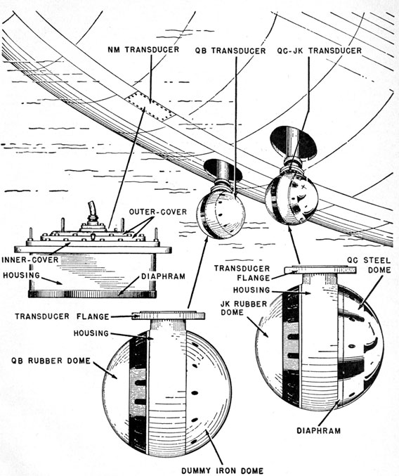
The model WCA-2 equipment uses 3 transducers and 1 hydrophone in three separate housings, as shown in figure 14-1. The NM is a magnetostriction transducer. The QC magnetostriction transducer and the JK Rochelle-salt hydrophone are housed in one sound head, called the
QC-JK. The QB is a Rochelle-salt transducer.
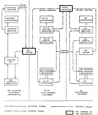
As shown in figure 14-2, the WCA-2 consists of
three systems.
One system, the QC-JK, uses the combination
sound head for echo ranging and listening. The
QC magnetostriction element is used for echo
ranging. The JK crystal hydrophone, which is
more sensitive than the QC magnetostriction transducer, is used for listening only. The QC and JK
units cannot be used simultaneously.
The second system uses the QB Rochelle-salt
transducer for echo ranging. The QB transducer
can be operated over a wider range of frequencies
than the QC because a crystal transducer is less
sharply resonant than a magnetostriction transducer of the same beamwidth.
The third system uses the NM transducer for
sounding only. The NM system requires no
training controls because the beam is directed
vertically downward.
Although the combined equipment consists
essentially of three separate complete systems,
each of the three systems uses one or more units
in common with one or both of the other systems.
Figure 14-1. -The three sound heads of the WCA-2 sonar equipment.
261
For example, the QB and QC-JK systems use the
same range indicator, and the sounding and
QC-JK systems use a common driver unit.
The units of the WCA are similar to standard
units discussed previously. The indicator is the
familiar rotating-light type used on early echo-ranging equipment. The sounding unit has its
own indicator, which is a rotating-light type.
The only major difference between surface-ship
echo-ranging equipment and the WCA is the use
in the WCA of a Rochelle-salt echo-ranging
system. The remote training unit provides for
slewing in either direction because the equipment
is used for listening most of the time.
Model WFA-1 Sonar Equipment
The model WFA-1 is a searchlight type of echo-ranging and listening equipment. It can be
operated in any one of the following modes:
(1) Listening, (2) echo-ranging, (3) communication, (4) torpedo-detection, (5) mine-detection,
and (6) monitoring own ship's noise.
Listening may be carried out over the frequency
range of from about 200 cps to about 100 kc.
Bearing is determined accurately by a bearing-deviation indicating (BDI) meter.
The frequency band for echo ranging is from
17.2 to 46 kc. The BDI circuits can be used with
echo-ranging operation for high accuracy. Higher
frequencies used in enemy waters give maximum
secrecy and highest bearing accuracy, but shorter
maximum ranges.
Telegraphic communication with other vessels
equipped with echo-ranging equipment is made
possible by the inclusion of a telegraph key that
keys the transmitter. The frequency range for
this mode of operation is the same as for echo
ranging.
For torpedo detection, the transducer beneath
the keel is rotated constantly. Any sound signal
picked up is fed through the receiver to the range
recorder, the stylus of which is synchronized with
the transducer rotation, as explained later.
For mine detection, the equipment is operated
as a short-pulse echo-ranging equipment using
either the topside transducer or the transducer
beneath the keel. In this mode of operation the
transducer is trained over a restricted arc of 30°
or 40° on each side of the bow. Mines and other
small navigational hazards can be detected at
ranges up to 600 yards. The short pulse produces
the high resolution that is necessary to detect
objects, such as mines at short ranges or in close
proximity to one another.
The WFA-1 equipment has two identical control stacks, one in the conning tower and the other
in the forward torpedo room. The conning tower
is the primary control point, but, in an emergency,
control can be switched to the forward torpedo
room. Figure 14-3 is an over-all pictorial diagram
of the equipment.
Figure 14-2. -Block diagram of the WCA-2 sonar equipment.
The WFA-1 has two sound head assemblies-one mounted on the deck, the other on the hull
near the keel.
The topside sound head is mounted vertically
on the main deck above the forward torpedo room
262
and is rotated by the topside training mechanism.
It is not retractable. This sound head consists of
three individual units, as follows:
1. A low-frequency (sonic) hydrophone, which
operates over a band of from 200 cps to 15 kc
for listening.
2. An intermediate-frequency (ultrasonic) transducer, which operates over a band of from
17.2 to 35 kc for echo ranging, and over a
band of from 12.5 to 35 kc for listening.
3. A high-frequency (ultrasonic) transducer,
which operates over a band of from 35 to 46
kc for echo ranging and over a band of from
31 to 100 kc for listening. These frequencies
are selected because the crystals that are used
operate at optimum efficiency in these ranges.
The lower sound head is mounted on a hoist-train shaft and functions like any retractable
searchlight transducer. It contains a single crystal transducer that operates over a band of from
22 to 32 kc, with most efficient operation at 27 kc
for both echo ranging and listening. The sound
head is spherical to prevent turbulence at high
speeds and to keep water noise at a minimum.
For torpedo detection, the lower sound head
is rotated at 12 revolutions per minute and the
range-recorder stylus sweeps across the chart in
about 4.6 seconds. Thus, each sweep of the stylus
occurs in one complete revolution of the transducer. Stylus travel is synchronized with the
transducer by a microswitch mounted on the
transducer shaft. The interval for fly-back of
the recorder stylus occurs while the transducer
rotates through the sector from 170° to 190°.
This sector is chosen for fly-back because during
this interval the transducer sweeps across the
ship's stern, and only unwanted sounds from the
screws are picked up. The bottom scale on the
recorder is graduated to indicate the bearing of all
received sounds. Torpedo detection is strictly a
listening function.
The receivers are of the sum-and-difference type
and have BDI meters, as well as RCG circuits.
Model QHB-1 Capacitive-Scanning Sonar Equipment
The model QHB-1 is almost identical with the
model QHB scanning sonar that is used on surface
ships. The QHB-a is described in chapter 6 of
this text. The QHB-1 differs from the QHB-a
in the following respects: (1) the QHB-1 has a
relative instead of a true PPI presentation-that
is, the bearings of signals are referred only to the
heading of the submarine; (2) it has a single-ping
keying feature as well as facilities for automatic
keying; and (3) its transducer is more ruggedly
constructed to withstand increased pressure without leaking. To prevent accidental keying, the
keying control mechanism of the QHB-1 must be
manually held in the closed position, either for
"automatic" or repetition keying or for single-ping
operation.
Model QLA F-M Scanning Sonar Equipment
DESCRIPTION
The QLA echo-ranging equipment is an f-m
scanning sonar. It provides a plan-position indication (PPI) of underwater objects within sound
range. It can be installed on submarines or surface vessels. In contrast to the searchlight-type
sonar, the f-m sonar provides continuous area
search coupled with the ability to detect very small
objects.
Sonar echo-returns from vessels, wakes, sand
banks, antisubmarine nets, and other submerged
objects that reflect ultrasonic energy are presented
both audibly and visually. The audible signals
are tones. The visual signals are intensity-modulated spots on the oscilloscope PPI indicator.
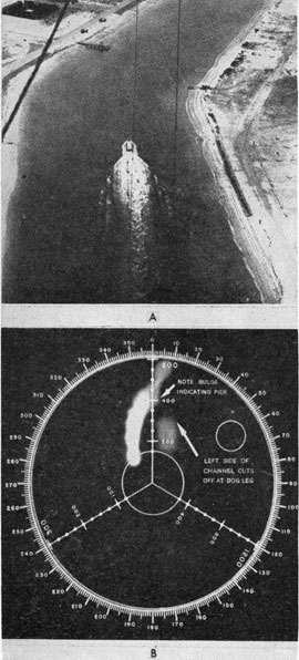
Figure 14-4, A, shows a surface ship entering a
channel. Figure 14-4, B, shows the QLA indication aboard the ship.
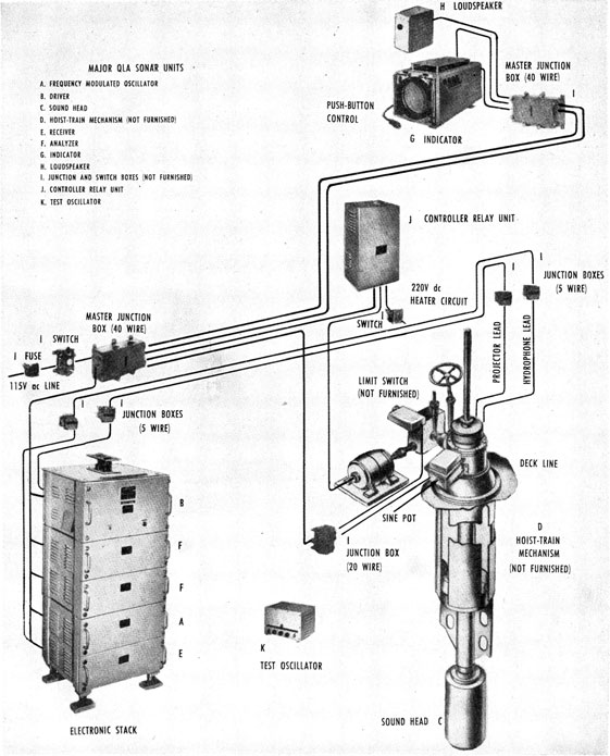
The QLA equipment and the location of the
major units are shown pictorially in figure 14-5.
The major units are (1) the frequency-modulated
oscillator, which generates the f-m signal; (2) the
driver, which amplifies the f-m signal and drives
263
Figure 14-4. -Typical QLA indication. A, Ship entering
channel; B, indication aboard the ship.
the projector; (3) the sound head, which contains
the projector and a hydrophone for receiving the
echo returns; (4) the hoist-train mechanism, which
raises, lowers, and rotates the sound head; (5) the
receiver, which heterodynes the returning echoes
with the oscillator signal; (6) the analyzer, which
uses a series of 20 filters which are sequentially
connected through electronic switch tubes to extract the frequency components of the heterodyned signal; and (7) the indicator, which intensity-modulates a cathode-ray tube beam in
accordance with the output of the analyzer and
which moves the beam to present a plan-position
indication. The loudspeaker makes the returning
echo audible, and the test oscillator is used to
adjust the sweep of the frequency-modulated
oscillator.
PRINCIPLES OF OPERATION
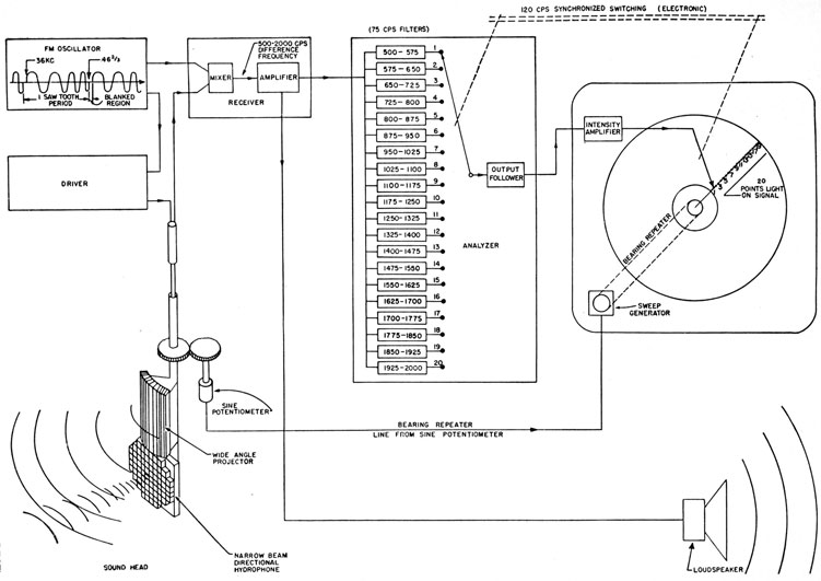
The functional block diagram of the QLA equipment is shown in figure 14-6. The f-m oscillator
develops the carrier signal, which varies with time.
At the beginning of an operating cycle the frequency is at a maximum of 46 2/3 kc, and at the
end of the cycle (several seconds later) it is at a
minimum of 36 kc. The frequency decreases
uniformly from the maximum to the minimum
value. At the end of an operating cycle the
frequency returns abruptly to its maximum value
and the cycle is repeated. The abrupt return or
fly-back to initial frequency requires only a few
milliseconds, during which time the projector is
silenced or "blanked."
If frequency is plotted vertically and time horizontally, the result is a curve having a sawtooth
pattern, as shown in figure 5-20. The downward
slope of the sawtooth signal represents a decrease
of frequency with time; the vertical line forming
the left side of the waveform represents the fly-back from minimum to maximum frequency.
The length or base of the sawtooth waveform corresponds to the time required for one operating
cycle. The frequency at any instant is different
from that at any other instant in an operating
cycle, and the frequency changes linearly with
time.
The QLA sound head contains a projector and a
hydrophone. The projector transmits sound
waves in a wide fan-shaped beam that has an arc
of about 80°. The sound waves are reflected by
any object in the beam of the projector. A small
part of the reflected energy returns to the sound
head as an echo, where it is picked up by the
sharply directive hydrophone.
During the time required for sound of a particular frequency to reach the target and to return
as an echo, the frequency of the projected sound
decreases. The longer the travel time, the greater
is the decrease and the greater is the difference in
frequency between the echo and the sound being
radiated as the echo arrives. Figure 5-20 shows
that the frequency difference, f, between echo and
signal is proportional to travel time. It is evident,
therefore, that the difference in frequency between
a returning echo and the signal being transmitted
when the echo is received, is proportional to the
range of the reflecting object.
The QLA sonar receiver mixes the echo with the
signal that is being transmitted and produces a
beat frequency equal to the difference in frequency
between the echo and the transmitted signal.
This frequency difference is presented to the
operator both audibly and visually. The audible
indication is a musical tone of constant pitch in
the loudspeaker; and the visual indication is a spot
of light on the cathode-ray indicator.
The difference frequency can be any frequency
between 0 and 10 2/3 kc. However, only frequencies
between 500 and 2,000 cycles per second are
analyzed and used to indicate range. This band
was chosen for technical reasons, including ear
sensitivity and filter-design considerations.
The analyzer resolves the frequencies between
500 and 2,000 cycles per second by use of 20 bandpass filters, 20 detectors, and an electronic switch.
The receiver output is applied to all 20 filters
(figure 14-6). The signal at the output of each
filter depends on the frequency of the signal and,
hence, on the range to the target. The filter outputs are rectified and applied to the intensity
amplifier of the indicator. The electronic switch
applies the output from filter 1 through filter 20
in sequence as brightening voltage to the oscilloscope. During this time the spot on the oscilloscope is moved radially outward from the center
of the screen. Thus, for each of the 20 filters there
is a corresponding radius on the screen. For
example, a signal with a frequency of 500 cycles
per second brightens the trace at a point 3/4 of an
inch from the center; a signal with a frequency of
2,000 cycles per second brightens the trace at a
point 3 inches from the center.
Range Scale
The range scale is selected by changing the rate
at which the f-m oscillator sweeps in frequency.
The rate at which the oscillator sweeps determines
the frequency difference corresponding to a given
range. The greater the rate of change of frequency, the greater is the difference (number of
cycles per second) representing a given range.
The oscillator can be swept at five rates. Thus,
the operator can select one of five range scales.
The rates of sweep are such that range scales of
300 feet, 300 yards, 600 yards, 1,200 yards, and
3,000 yards are available. The periods of sweep
corresponding to these ranges are 0.67 second, 2.0
seconds, 4.00 seconds, 8.00 seconds, and 20
seconds, respectively.
Bearing of the Indicator Sweep
The bearing of the hydrophone determines the
angular displacement of the sweep on the indicator.
As shown in figure 14-6, the hydrophone training
mechanism operates through a sine potentiometer
and a sweep generator and orients the trace so
that the trace is at the same angle (with respect
to the vertical) that the hydrophone axis is with
respect to the heading of the ship. The indication
of any echo on the screen therefore appears in a
position corresponding to its relative bearing
Maximum Scanning Rate
The maximum angular rate of speed at which the
QLA sonar can scan depends on the maximum
range for which the equipment is being operated.
The projector transmits sound into the water over
an arc of 80°-that is, 40° on each side of the
hydrophone. Thus, a particular target is in the
field of the projector for about 40° of its rotation
before it is received by the hydrophone. The
sound head must rotate less than 40° in the' time
required for the sound to travel to the maximum
range and back.
The maximum useful speed of rotation of the
sound head (in revolutions per minute) is approximately 5,000 divided by the range in yards. On
short ranges the speed is limited by the characteristics of the electrical system to about 10 revolutions
per minute. In a particular installation the
choice of speeds is dictated by the service intended. The speed of rotation at long ranges can
266
Figure 14-6. -Functional block diagram of the QLA f-m sonar.
267
be increased if the search angle is limited to about
50°; the whole area can then be covered by allowing this search angle to progress from one sweep
to the next.
DOPPLER EFFECT
The QLA sonar uses the frequency of an echo in
determining range. Therefore, any doppler causes
an error in the measurement of range. The error
is 75 cycles per second (or one channel on the
screen of the cathode-ray tube) for each 2 ½ knots of
relative range rate. The error causes the measured
range to be too long when closing, and too short
when opening, the target. In ranging on moving
vessels, the larger part of the echo comes from the
wake. The doppler effect in this case is due
largely to own ship's doppler.