|
Folks,
24 Inch Searchlight, Model 24-G-20, Spec 17S21, 1944, covers a typical 24 inch U.S.N. Navy carbon arc searchlight of WW II. These were used for signalling, visual search, navigation and even fire control.
We thank Ed Zajkowski for his generous loan of the original document used to create this online version.
Please report any typos, or particularly annoying layout issues with the Mail Feedback Form for correction.
Richard Pekelney
Webmaster
|
|
INSTRUCTIONS
AND RENEWAL PARTS
MODEL 24-G-20
24-INCH SEARCHLIGHT
NAVY DEPARTMENT CONTRACT
NXs-4296
G-E SERIAL NUMBERS
Searchlight
50167 to 51516 incl.
NAVY SERIAL NUMBERS
Searchlight
1802 to 3151 incl.
|
April, 1944 (1175) |
GEI-17159A
Supersedes GEI-17159
|
|
|
INSTRUCTION BOOK
FOR
24-INCH SEARCHLIGHT
MODEL 24-G-20
Navy Department Specification 17S21 (INT) dated 1 October 1942
INSTALLED UNDER THE COGNIZANCE
OF THE
BUREAU OF SHIPS
Navy Department
Washington, D. C. |
|
BUREAU OF SHIPS FILE NUMBER |
|
S66-17S21-2, Alt. 0
|

|
3
|
|
TABLE OF CONTENTS
| Subject |
Page |
| Index of Illustrations |
9 |
| Index to G-E Drg. No. and Bureau File No. |
10 |
| The Contract Guarantee |
11 |
|
| INSTRUCTIONS FOR SEARCHLIGHT |
|
| GENERAL DESCRIPTION |
13 |
| CARBON-ARC LAMP |
13 |
| A. Description |
13 |
| 1. General |
13 |
| 2. Rating |
13 |
| 3. Carbons |
13 |
| 4. Positive-carbon Drive |
15 |
| (a) Positive-carbon Feed (Explanation) |
15 |
| (b) Thermostat System |
16 |
| 5. Negative-carbon Drive |
16 |
| (a) Negative-carbon Drive (Explanation) |
16 |
| (b) Negative-carbon Drive (Details) |
19 |
| 6. Lamp (Feed) Motor |
19 |
| 7. Arc-voltage Adjusting Knob |
20 |
| 8. Lamp-focusing Screw |
20 |
| 9. Manual-carbon Drive |
20 |
| (a) Positive-carbon Drive (Explanation) |
20 |
| (b) Negative-carbon Drive (Explanation) |
20 |
| 10. Ventilation of Lamp |
20 |
| 11. Lamp Circuit |
20 |
| B. Operation |
20 |
| 1. General |
20 |
| 2. Carboning |
21 |
| 3. Starting the Arc |
23 |
| 4. Normal Appearance of Arc |
23 |
| 5. Manual Operation of Lamp |
24 |
| 6. Extinguishing the Arc |
24 |
| 7. Precaution |
24 |
| C. Maintenance |
24 |
| 1. Care |
24 |
| (a) General |
24 |
| (b) Lamp Heads |
25 |
| (1) Reaming Heads |
25 |
| (2) Brush Contacts |
25 |
| (3) Feed Rollers |
25 |
|
4
|
|
TABLE OF CONTENTS (Continued)
| Subject | Page |
| C. Maintenance (Cont'd) |
| (c) Lamp Mechanism |
25 |
| (d) Carbons |
25 |
| 2. Cleaning |
25 |
| (a) Lamp and Lamp Mechanism |
25 |
| 3. Lubrication |
25 |
| (a) Lamp |
25 |
| 4. Parts Replacement |
25 |
| (a) General |
25 |
| (b) Replacing Feed Rollers |
25 |
| (c) Replacing Positive Obturator |
26 |
| (d) Replacing Positive Nose Cap |
26 |
| (e) Replacing Positive Contacts |
26 |
| (f) Replacing Negative Nose |
27 |
| (g) Replacing Negative Contact |
27 |
| (h) Replacing Thermostat Strips |
27 |
| (i) Replacing Thermostat Lens |
27 |
| 5. Removing Lamp from Drum |
27 |
| 6. Replacing Lamp in Drum |
27 |
| D. Adjustments |
28 |
| 1. Alignment of Heads |
28 |
| 2. Alignment of Obturator |
28 |
| 3. Arc-voltage Adjustment |
28 |
| 4. Arc Brush-contact Pressure |
28 |
| 5. Adjusting Thermostat-lens Position |
29 |
| 6. Adjusting Thermostat Contacts |
29 |
| 7. Adjusting Positive-carbon-feed Rod |
29 |
| 8. Adjusting Arc-voltage Regulator Solenoid |
30 |
| (a) Solenoid Plunger |
30 |
| (b) Counterbalance |
30 |
| (c) Arc-voltage Adjustment |
30 |
| (d) Pawls |
30 |
| (e) Pawl Springs |
30 |
| (f) Ratchets |
30 |
| E. Faults and Their Corrections |
31 |
| 1. General |
31 |
| 2. Arc Current-High or Low |
31 |
| 3. Arc Voltage-High or Low |
31 |
| 4. Positive Head Fails to Rotate |
31 |
| 5. Positive Carbon Does Not Feed |
31 |
| 6. Positive Carbon Feeds Continuously |
32 |
| 7. Positive Carbon Tip is Held at a Point Away from Arc-image Focal Line |
32 |
|
5
|
|
TABLE OF CONTENTS (Continued)
| Subject | Page |
| E. Faults and Their Correction (Cont'd) |
| 8. Excessive Variation in Positive-carbon Projection |
32 |
| 9. Negative Carbon Does Not Feed at Start |
32 |
| 10. Negative Carbon Feeds Sluggishly |
32 |
| 11. Negative Carbon Does Not Retract after Striking Positive Carbon |
32 |
| 12. Arc Breaks Repeatedly |
32 |
| 13. Arc Voltage Changes when Drum is Elevated or Depressed |
33 |
| 14. Excessive Arc-voltage Variation |
33 |
| 15. Arc Length is Too Short |
33 |
| 16. Arc Length is Too Long |
33 |
| RHEOSTAT |
34 |
| A. Description |
34 |
| B. Adjustment |
34 |
| PROJECTOR |
35 |
| A. Description and Operation |
35 |
| 1. General |
35 |
| 2. Pedestal |
35 |
| 3. Turntable and Arms |
35 |
| (a) General |
35 |
| (b) Shutter Switch |
35 |
| (c) Train Clamp |
35 |
| (d) Collector Rings, Thermo-Tector, Capacitor, Resistor Unit, and Turntable Wiring |
35 |
| (e) Elevation Clamp |
35 |
| 4. Drum |
35 |
| (a) General |
35 |
| (b) Barrel |
36 |
| (c) Lamp Housing |
36 |
| (d) Rear Door and Reflector |
36 |
| (e) Front Door and Dome Glass |
36 |
| (f) Ventilating System |
36 |
| (1) General |
36 |
| (2) Ventilating Motor |
36 |
| (g) Iris Shutter |
36 |
| (h) Signaling Shutter and Operating Mechanism |
36 |
| (i) Positive-carbon Tube |
36 |
| (j) Arc-image System |
36 |
| (k) Peep Sight |
37 |
| (l) Telescope Bracket and Beam Sights |
37 |
| (m) Lamp Instruction Plate |
37 |
| (n) Directing the Searchlight Beam |
37 |
|
6
|
TABLE OF CONTENTS (Continued)
| Subject | Page |
| A. Description and Operation (Coned) |
| 5. Signal Keys |
37 |
| 6. Drum Terminal Board |
37 |
| B. Maintenance |
37 |
| 1. General |
37 |
| 2. Inspection and Cleaning |
37 |
| (a) General |
37 |
| (b) Interior of Drum |
37 |
| (c) Cleaning and Polishing Reflector and Dome Door Glass |
37 |
| 3. Lubrication |
38 |
| (a) Lubrication of Searchlight |
38 |
| (b) Lubrication of Shutters |
38 |
| (c) Lubrication Precautions |
38 |
| 4. Parts Replacements |
38 |
| (a) Removing and Replacing Reflector |
38 |
| (b) Removing and Replacing Iris Shutter |
39 |
| (c) Removing and Replacing Signaling Shutters |
39 |
| (d) Removing and Replacing Drum |
39 |
| (e) Removing and Replacing Dome Door Glass |
39 |
| C. Adjustments |
39 |
| 1. Arc-image Screen |
39 |
| 2. Focus |
39 |
| 3. Signaling-shutter Operating Mechanism |
40 |
| (a) Adjustment of Buffer-spring Tension |
40 |
| (b) Adjustment of the Shutter-operating-mechanism Armature |
40 |
| D. Faults and Their Correction |
40 |
| 1. Signaling-shutter Operating Mechanism |
40 |
| 2. Failure of Shutter to Operate |
41 |
| 3. Sluggish or Erratic Operation of Shutter |
41 |
| INSTALLATION |
41 |
| A. Unpacking the Searchlight |
41 |
| B. Installation of Searchlight |
41 |
| C. Installation of Rheostat |
41 |
| D. Installation of Signaling Keys |
41 |
| E. Testing after Installation |
41 |
| SHIP'S SEARCHLIGHT SPARE PARTS |
42 |
| INDEX TO CATALOG NUMBERS |
44 |
|
7
|
TABLE OF CONTENTS (Continued)
RENEWAL PARTS FOR SEARCHLIGHT
| Subject | Page |
| PEDESTAL AND TURNTABLE |
49 |
| Bearing Support |
49 |
| Contact Rings |
49 |
| Brush Rigging |
49 |
| Master Switch |
49 |
| TRUNNIONS AND BRAKE SEGMENTS |
55 |
| SIGNALING KEY, TYPE CG-26014 |
56 |
| DRUM |
56 |
| Reflector Frame and Dome |
56 |
| Glass Dome for Front Door |
57 |
| Arc-image Screen |
58 |
| Fan Housing |
59 |
| Ventilating Motor |
59 |
| Brush Holders |
61 |
| Iris Shutter |
61 |
| Signaling Shutter |
62 |
| SIGNALING KEY, TYPE CMI-26003 |
65 |
| CABLES |
65 |
| GAGES AND REAMERS |
66 |
| CARBON-ARC LAMP |
66 |
| RHEOSTAT |
81 |
| STANDARD HARDWARE |
83 |
| INSTALLATION PLAN (Drg. WW-8259278) |
Bound in Back of Book |
|
8
|
|
This page is blank.
|
9
|
INDEX OF ILLUSTRATIONS
| Fig. |
Title | Page |
| 1 |
Front and Rear Views of Searchlight |
12 |
| 2 |
Carbon-arc Lamp (Parts Identified) |
14 |
| 3 |
Thermostat System |
15 |
| 4 |
Diagram of Carbon-arc Lamp Gearing |
15 |
| 5 |
View of Carbon-arc Lamp Mechanism (Parts Identified) |
16 |
| 6 |
View of Carbon-arc Lamp Mechanism (Parts Identified) |
17 |
| 7 |
Carbon-arc Lamp Mechanism Case (Covers Removed) |
18 |
| 8 |
View of Lamp Box Showing Manual Control |
20 |
| 9 |
Ventilating System |
21 |
| 10 |
Schematic Wiring Diagram of Ship's Installation Circuit |
22 |
| 11 |
Normal Appearance of Arc |
23 |
| 12 |
Lubrication Chart for Lamp Mechanism |
26 |
| 13 |
Searchlight Showing Lamp in Position |
28 |
| 14 |
Alignment of Heads |
29 |
| 15 |
Schematic Wiring Diagram (Rheostat) |
34 |
| 16 |
Rheostat Wiring Diagram |
34 |
| 17 |
Diagram of Arc-image System |
37 |
| 18 |
Front View of Searchlight Showing Detail of Front Door Hinge and Latch for Holding Door Open |
48 |
| 19 |
Cross Section View of Pedestal and Turntable |
50 |
| 20 |
Side View of Pedestal and Turntable |
51 |
| 21 |
Rear View of Searchlight Showing Detail of Rear Door Hinge and Latch for Holding Door Open |
52 |
| 22 |
Pedestal with Cover Removed |
53 |
| 23 |
Master Switch |
54 |
| 24 |
Side View of Drum |
55 |
| 25 |
Signal Key (Mounted on Searchlight) |
56 |
| 26 |
Mounting of Glass Dome and Reflector
Glass Dome Mounting
Reflector Mounting
Alignment of Reflector |
57 |
| 27 |
Peep Sight Glass |
57 |
| 28 |
Arc-image Screen |
58 |
| 29 |
Cross Section of Fan and Ventilating Motor Housing |
59 |
| 30 |
Ventilating Motor |
60 |
| 31 |
Iris Shutter |
62 |
| 32 |
Signaling Shutter |
63 |
| 33 |
Signaling Shutter Operating Mechanism |
64 |
| 34 |
Remote Signaling Key |
65 |
| 35 |
Reamers and Gages |
66 |
| 40 |
Positive Nose and Rotating Mechanism (Disassembled) |
67 |
| 40A |
Positive Nose |
68 |
| 40B |
Rotating Mechanism |
69 |
| 41 |
Negative-carbon Head (Disassembled) |
70 |
| 41A |
Negative-carbon Head |
71 |
| 42 |
Carbon-arc Lamp (Side View) |
72 |
| 43 |
Carbon-arc Lamp (Side View) |
73 |
| 43A |
Control Mechanism Assembly |
74 |
| 44 |
View of Carbon-arc Lamp Mechanism |
76 |
| 45 |
View of Carbon-arc Lamp Mechanism |
78 |
| 45A |
Positive-carbon Shaft Assembly |
79 |
| 46 |
Lamp Mechanism Motor |
80 |
| 47 |
Rheostat |
81 |
|
10
|
INDEX TO G-E DRAWING NUMBERS AND BUREAU OF SHIPS
FILE NUMBERS
G-E
Drawing No. |
Title of Drawing |
Bureau File No. |
| 12615-43 |
Rheostat (Ward Leonard) (Arc Lamp) |
9311 S6600 1650 |
| T-4935411 |
Diagram of Carbon Positions |
9311 S6600 1645 |
| T-4935457 |
Ball Bearings |
9311 S6600 1625 |
| W-4975946 |
Main Line Switch |
9311 S6600 1610 |
| W-.4975964 |
Motor (Feeding) Model 5BY8A8 |
9311 S6600 1629 |
| W-4975965 |
Motor (Ventilating) Model 5BC46A37 |
9311 S6600 1616 |
| T-5322130 |
Diagram of Gearing |
9311 S6600 1647 |
| WW-5329426 |
Assembly of Lamp Mechanism |
9311 S6600 1628 |
| W-5229518 |
Front Door |
9311 S6600 1619 |
| W-5329519 |
Iris Shutter |
9311 S6600 1620 |
| W-5329521 |
Arc Viewing Screen |
9311 S6600 1622 |
| W-5329523 |
Signal Shutter |
9311 S6600 1624 |
| W-5329524 |
Negative Carbon Head |
9311 S6600 1630 |
| W-5329525 |
Positive Carbon Nose |
9311 S6600 1631 |
| W-5329526 |
Rotating Mechanism |
9311 S6600 1632 |
| W-5329527 |
Positive Feed Magnet |
9311 S6600 1633 |
| W-5329528 |
Plates and Supports |
9311 S6600 1634 |
| W-5329529 |
Gears and Shafts (Negative Feed) |
9311 S6600 1636 |
| W-5329530 |
Gears and Shafts (Positive Feed) |
9311 S6600 1637 |
| W-5329531 |
Control Mechanism |
9311 S6600 1638 |
| W-5329532 |
Brackets and Support |
9311 S6600 1642 |
| T-5992544 |
Side Plates |
9311 S6600 1635 |
| T-5992545 |
Feed Shafts |
9311 S6600 1639 |
| T-5992546 |
Voltage Regulator Solenoid |
9311 S6600 1640 |
| T-5992547 |
Shaft Pawls and Stop (Negative Feed) |
9311 S6600 1641 |
| T-5992548 |
Carbon Head Support |
9311 S6600 1643 |
| T-5992549 |
Thermostat |
9311 S6600 1644 |
| T-5992550 |
Diagram of Lubricating System |
9311 S6600 1646 |
| T-5992551 |
Tools |
9311 S6600 1648 |
| T-5993106 |
Guide for Iris Shutter |
9311 S6600 1621 |
| T-8004931 |
Reamer for Positive Head |
9311 S6600 1649 |
| WW-8009171 |
Assembly of Terminal Boards, Cover and Thermo-Tector |
9311 S6600 1612 |
| W-8009460 |
Paint Notes |
9311 S6600 1608 |
| WW-8259222 |
Signal Shutter Operating Mechanism |
9311 S6600 1617 |
| WW-8259227 |
List of Drawings |
9311 S6600 1601 |
| WW-8259228 |
Assembly of Drum |
9311 S6600 1605 |
| WW-8259229 |
Signal Key and Capacitor Unit |
9311 S6600 1611 |
| WW-8259230 |
Elevation and Train Brakes and Stowing Locks |
9311 S6600 1613 |
| WW-8259231 |
Assembly of Trunnions and Brake Segment |
9311 S6600 1607 |
| WW-8259234 |
Contact Rings, Brush Holder and Brush |
9311 S6600 1609 |
| WW-8259236 |
Assembly of Turntable |
9311 S6600 1603 |
| WW-8259237 |
Assembly of Wiring, Cables and Terminals |
9311 S6600 1606 |
| WW-8259239 |
Pedestal Assembly |
9311 S6600 1604 |
| WW-8259248 |
Rear Door Assembly |
9311 S6600 1618 |
| WW-8259249 |
Projector Assembly |
9311 S6600 1602 |
| WW-8259254 |
Assembly of Ventilator |
9311 S6600 1615 |
| WW-8259278 |
Installation Plan |
9311 S6600 1623 |
| WW-8259299 |
Telescope Bracket and Sights, Peep Sight, Stop, and Latch |
9311 S6600 1614 |
| W-8259824 |
Handles and Covers |
9311 S6600 1627 |
| W-8259830 |
Diagram of Ventilating System |
9311 S6600 1626 |
| WW-8259227 |
List of Drawings |
|
|
11
|
|
CONTRACT GUARANTEE
Report of failure of any part of this equipment during its service life shall be made to the Bureau of Ships in accordance with current instructions. The report shall cover all details of the failure and shall include the date of installation of the equipment. For reports of failures during the specified guarantee period, see the current revision of Bureau of Engineering circular letter No. 40 original date 26 March, 1936
TABLE OF PERTINENT DATES
(a) Contract No ______________ Date of contract ______________
(b) Serial No. of projector ______________
(c) Date of acceptance by the Navy ______________
(d) Approximate date of delivery at contract destination ______________
(e) Date of completion of installation ______________
(f) Date placed in service ______________
(g) Date of expiration of contract guarantee______________
Blank spaces shall be filled in at time of installation. Operating personnel shall also fill in the dates on the date plate located below the model nameplate on the projector.
ORDERING NEW PARTS
In order to expedite handling of requisitions for replacement material, the requisitions should include complete searchlight nameplate data, searchlight model number, manufacturer, instruction book number, and manufacturer's drawing number, catalog number, and reference number as given in the instruction book.
|
12
|
|
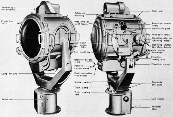
Fig. 1. Front and Rear Views of Searchlight
|
13
|
24-INCH SEARCHLIGHT
MODEL 24-G-20
INSTRUCTIONS FOR SEARCHLIGHT
PART I
|
|
GENERAL DESCRIPTION
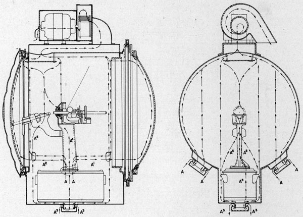
This searchlight is intended primarily for signaling and secondarily for navigational use. It consists of a stationary base which is secured to the searchlight platform, a turntable which carries the two trunnion arms and rotates in train on the base, and a drum which is pivoted on the trunnion arms to allow the drum to be elevated and depressed.
The drum contains an automatic high-intensity carbon-arc lamp which is operated from a d-c power supply. At the rear of the drum is a Stellite metal reflector. At the front of the drum there is a dome glass, an iris shutter for shutting off the search-
|
|
light beam, and a high-speed sector-vane shutter which may be operated remotely for signaling with the searchlight beam. Handles at the rear of the drum provide a means of swinging the searchlight in train and elevation to direct the beam of light. The drum may be rotated continuously in train and between angles of 110-degree elevation and 30-degree depression.
The carbon-arc lamp is designed for operation in series with rheostat (which is mounted below deck) from a d-c source of 105 to 125 volts. The arc current should be adjusted for 75 to 80 amperes with 65 to 70 volts across the arc. One set of carbons will burn approximately 1 3/4 hours.
|
PART II
|
|
CARBON-ARC LAMP
A. Description
1. General
The carbon-arc lamp is of the high-intensity type in which cored carbons are used. The carbons are mounted in geared heads (see Fig.2) and automatically positioned to maintain the arc voltage substantially constant and the crater of the positive carbon at the focal point of the reflector. The positive carbon is aligned with the optical axis of the reflector, and is continuously rotated to prevent unsymmetrical burning of the carbon. The negative carbon is inclined at an angle of 16 degrees to the positive carbon.
The lamp is held in the lamp housing by means of four lugs which slip into side grooves. A focusing latch at the rear of the lamp box engages the end of the focusing screw.
The mechanism for operating the lamp is located in the lamp box which serves as a base for the lamp. The mechanism and controlling devices are completely self-contained in the lamp.
Current is conducted to the carbon through spring-backed metal-brush contacts which press against the carbons. The head assemblies are so insulated |
|
that only the brush contact can conduct current to the carbons.
2. Rating
The searchlight carbon-arc lamp must be operated at an arc current of 75 to 80 amperes and an arc voltage of 65 to 70 volts. The searchlight and rheostat in series operate from a d-c supply of 105 to 125 volts.
3. Carbons
Carbons, Type 24-75, purchased in accordance with Supplementary General Spec, for Machinery, SGS (66)-122, are the only carbons suitable for these lamps for use at 75 to 80 amperes.
Dimensions are as follows:
Positive: 0.433 in. diameter, 18 in. long, core 0.216 in. diameter.
Negative: 0.433 in. diameter, 8 3/4 in. long, core 0.1 in. diameter.
Carbons should be handled carefully and be protected against moisture. Carbons which have become damp should be dried out before using.
The carbons consist of hard-carbon shells with cores of special materials. In operation, the core
|
14
|
|
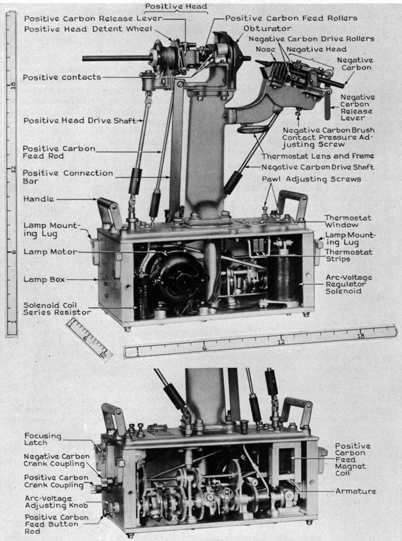
Fig. 2. Carbon-arc Lamp (parts identified)
|
15
|
|
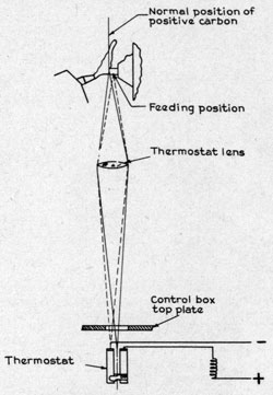
Fig. 3 Thermostat System
|
|
of the positive carbon is vaporized, forming a hollow crater facing the reflector. An intensely luminous ball of gas rotates in the crater and projects light on the reflector.
4. Positive-carbon Drive
The lamp motor inside the lamp box rotates the positive head continuously by direct gearing through an "over-running" or "free-wheeling" clutch of the ball-pawl type and a gear train.
(a) Positive-carbon Feed (Explanation)
The positive carbon is carried in the center of the continuously rotating positive head, and is fed by two serrated rollers. These rollers are driven by the positive-head gearing, which is an elliptical gear train in which the intermittent holding of the
|
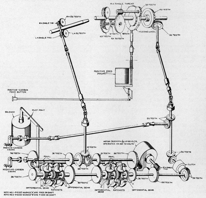
Fig. 4. Diagram of Carbon-arc Lamp Gearing
|
16
|
|
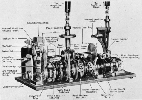
Fig. 5. View of Carbon-arc Lamp Mechanism (parts identified)
|
|
detent wheel by the positive-carbon feed rod causes the rotating motion of the positive head to give a feeding motion to the positive-carbon feed rollers. When the detent wheel is not held, no feeding of the positive carbons occurs.
The positive-carbon feed rod is operated by the positive-carbon feed-magnet armature when the lamp is operating automatically, or may be held in the feeding position by holding in the positive-carbon feed button at the rear of the lamp housing. Releasing the button stops the feeding. The magnet is controlled by the thermostat as described on this page under "Thermostat System."
(b) Thermostat System (Fig. 3)
The thermostat has two bimetallic strips attached to an insulation block. These strips bend with heat, and they are so assembled that changes in ambient temperature cause the bending to be the same in both strips.
The free end of each strip carries a contact; these contacts are made to close when the rear strip is heated more than the front strip.
A lens mounted on the negative-head supporting column collects light rays from the arc and projects them through a window in the top plate of the lamp box where they converge on the thermostat. If the positive-carbon projection is of the correct
|
|
length (9/16 in.), the converging rays strike the space between the thermostat strips.
As the positive carbon burns away, the concentrated spot of light moves out of the space between the strips and strikes the rear strip. The heat of the concentrated light bends the strip and causes it to close the contact, energizing the positive-carbon feed magnet, and thus causing the carbon to be fed into the arc until the light spot has moved into the space between the strips. This allows the rear strip to cool, opening the circuit and de-energizing the magnet. This stops the feeding of the carbon.
5. Negative-carbon Drive (Fig. 5 and 6)
(a) Negative-carbon Drive (Explanation)
The arc-voltage-regulator circuit, which is the automatic electric control of the mechanical negative-carbon drive gearing, consists of a solenoid coil in series with a resistor. The resistor is for the purpose of compensating for the change in resistance of the coil due to changes in temperature. This arrangement will cause the current (and likewise the magnetic pull) in the solenoid to be practically constant for the adjusted arc voltage, regardless of change in coil resistance due to temperature changes.
|
17
|
|
Fig. 6. View of Carbon-arc Lamp Mechanism (parts identified)
|
|
The magnetic pull of the solenoid is applied to a plunger connected to a counterbalanced rocker arm and balanced by an adjustable tension spring. The counterbalance is adjusted to compensate for the weight of the plunger so that the rocker arm will be balanced in all elevation positions of the searchlight drum. By adjustment of the pull of the spring on the rocker arm (by means of the arc-voltage adjusting knob), the voltage required across the solenoid to counteract this spring pull and bring the rocker arm to the horizontal or normal position can be varied.
The normal position of the rocker arm can be determined mechanically by pushing in on the negative-carbon-crank coupling which causes the normal-position pin to enter its seat in the rocker arm, thus holding the rocker arm in place.
The motion of the rocker arm caused by variation in arc voltage (due to striking and "drawing-out" the arc, burning away of negative carbon, variations in supply-bus voltage, etc.) transmits to the pawl-operating shaft through a link connection.
The pawl-operating shaft, which rotates slightly with the motion of the rocker arm, is a mechanical control of the negative-carbon drive gearing. This gearing is so arranged that the continuously rotating motor-driven shaft can be either connected to |
|
feed or retract the negative carbon or disconnected to allow the negative carbon to remain stationary.
The feed gearing and retract gearing are similar gear trains which are driven from the same shaft. The operation of the pawls determines which train will be used to drive the negative carbon. Each of the gear trains has two differential gear assemblies, one for fast and one for slow drive, each of which carries a notched ratchet on its spider. These differential gear assemblies normally idle with the drive shaft and transmit no motion to the negative carbon. By holding the slow ratchet, the fast ratchet continues to idle in the same direction, and the negative carbon is driven at slow speed. By holding the fast ratchet, the slow ratchet idles in the reverse direction, and the negative carbon is driven at fast speed.
With the rocker arm in the normal position (as determined by seating the normal-position pin) the pawl-operating shaft will be held at a fixed point. In this position, all the pawls should clear the outer surface of the ratchets, and rotation of the drive shaft should not rotate the negative-carbon drive shaft. With the normal-position pin disengaged, and the desired arc voltage of 65 to 70 volts applied across the lamp terminals, the arc-voltage adjusting knob should be set at the proper notch to hold the rocker arm at the normal position.
|
18
|
Fig. 7. Carbon-arc Lamp Mechanism Case (covers removed)
|
19
|
|
If the arc voltage changes from the arc-voltage-adjustment setting, the solenoid plunger will be pulled down (if the voltage is greater), or the counterbalance will be pulled down by the tension spring (if the voltage is less). Either of these motions will move the pawl-operating shaft. A small increase in voltage will engage the slow-feed pawl in the slow-feed ratchet. Additional increase in voltage will cause a greater movement of the pawl-operating shaft and engage the fast-feed pawl in the fast-feed ratchet. As the negative carbon is fed, the arc voltage drops, first disengaging the fast-feed pawl and then the slow-feed pawl as the desired arc voltage is reached. In order to provide a positive mechanical disengagement of the slow-feed pawl, a trip arm is mounted on the drive shaft which mechanically disengages the pawl on each revolution. If the arc voltage is still above normal, the slow-feed re-engages, and the negative carbon is further adjusted.
The action of the retract pawls is identical with that of the feed pawls, with the exception that they are engaged only when the arc voltage is less than the arc-voltage-adjustment setting, and the resulting motion is a retracting of the negative carbon which causes the arc length to increase and the arc voltage to rise to normal.
(b) Negative-carbon Drive (Details) (Fig. 7)
Lamp motor (9), through worm (10), drives worm gear (30) keyed to shaft (16). This shaft rotates continuously while the lamp is in operation. Gears (14-15), (22-23), (24-25), and (28-29) are attached to each other as grouped here, but are free on shaft (16). The double bevel gears (18) are keyed to the shaft and rotate continuously. Bevel gears (2) and ratchets (17), (20), (26), and (27) are attached to differential spiders (21) which are free In the shaft.
Negative-carbon-drive shaft (1) is connected to tile negative-carbon-drive rollers and feeds or retracts the negative carbon. Bevel gear (5) is attached to shaft (1).
The gear trains on the right and left sides of gear (5) are identical. The gearing to the left feeds and the gearing to the right retracts the negative carbon.
Shaft (13) carries pawls which engage the ratchets (17), (20), (26), and (27). This shaft (13) is operated by the solenoid. When the arc voltage is normal at between 65 to 70 volts, the shaft (13) is in the position to hold the pawls clear of the ratchets. Under this condition, the bevel gears (2) are idled by the driving gears (18), and there is no tendency to drive the shaft (11).
|
|
When the lamp-control switch is closed, the solenoid plunger is drawn down, engaging the pawls on both ratchets (17) and (20). This gives a fast feed to the negative carbon by preventing forward rotation of the spiders (21) on the feed differentials, and by driving the gear (23) which, in turn, drives shaft (11) through gear (3). Gear (4) drives gear (5) and rotates shaft (1), feeding the negative carbon.
When the fast-feed gearing is in operation, the slow-feed ratchet will idle slowly in a reverse direction.
When the carbons touch, the voltage on the solenoid is greatly reduced; its plunger is drawn up by the spring, and it turns the shaft (13) so that the pawls on the ratchets (17) and (20) are disengaged and those on the ratchets (26) and (27) of the retract gears are engaged. The negative carbon is then retracted at high speed, and the arc is established. As the arc length is increased, the voltage approaches normal and the fast-retract pawl on ratchet (26) is released by movement of the rocker arm; the carbon is slowly retracted by the slow pawl on ratchet (27), and the pawl being disengaged when the normal arc voltage is reached.
Small changes in arc voltage, such as two volts increase, cause the solenoid plunger to move and a pawl to engage the ratchet (17) of the slow-feed differential. The gear (18) driving through the gears (2) then rotates gears (15), (14), (12), (3), (4), and (5) and feeds the negative carbon until normal arc voltage is reached and the pawl is tripped from the ratchet (17).
Cams (19) lift the engaged slow pawls once during each revolution of the double bevel gears (18) so there is no tendency for them to hang on the ratchets, especially near the normal arc voltage where the pull of the tension spring and the opposing pull of the solenoid are about equal. At this point, there is minimum torque on the rocker arm which moves the pawls. Retraction is accomplished in the same manner by the slow-retract gearing if the arc voltage goes two or more volts below the normal setting.
6. Lamp (Feed) Motor
The lamp motor starts to run immediately and continues as long as the carbon-arc-lamp circuit is energized. This motor rotates the positive carbon continuously and feeds it under control of the thermostat, and drives the negative carbon under control of the arc-voltage regulator. The motor is a d-c, shunt-wound motor and it is rated as follows: Volts-65-70, Amperes-0.8, Horsepower-1/30, Rpm-3000.
This motor is the G-E Model No. 5BY8A8.
|
20
|
|
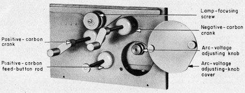
Fig. 8. View of Lamp Box showing Manual Control
|
|
7. Arc-voltage Adjusting Knob
By removing the cover at the rear of the lamp housing, the arc-voltage adjusting knob (see Fig. 8) is made accessible. This right-hand-knurled knob controls a lever attached to the tension spring. Turning the knob clockwise increases the tension on the spring and raises the arc voltage. Counterclockwise adjustment lowers the arc voltage.
8. Lamp-focusing Screw
The lamp-focusing screw (see Fig. 8) engages a focusing latch at the rear of the lamp box (see Fig. 2). By turning this screw, the lamp may be moved forward or backward, the lamp mounting lugs sliding in grooves in the lamp housing.
9. Manual Carbon Drive
(a) Positive-carbon Drive (Explanation)
At the rear end of the lamp housing are two crank handles (negative-carbon crank and positive-carbon crank) (see Fig. 8), normally held out of engagement with the drive gearing by springs. The left-hand crank, when pushed toward the lamp and rotated in the clockwise direction, will rotate the positive head and carbon. This rotation of the crank automatically declutches the positive head from the irreversible worm drive by means of the clutch, which engages only when the lamp motor is driving the mechanism. When it is desired to feed the positive carbon forward, the positive-carbon feed button is pressed in, which causes the detent to engage the detent wheel and feed the positive carbon forward. When the positive crank is turned, the rotation of the positive carbon will be maintained, even when it is being fed forward.
(b) Negative-carbon Drive (Explanation)
The right-hand crank, when pushed toward the lamp and rotated feeds the negative carbon for the clockwise rotation and retracts it for the counter-
|
|
clockwise rotation. When the right-hand crank is engaged and turned, the shaft (11, Fig. 7) directly behind this crank causes the beveled gears (4 and 6, Fig. 7) to rotate the negative drive shaft (1).
10. Ventilation of Lamp (Fig. 9)
A d-c shunt motor, mounted on top of the drum, drives the exhaust fan. This motor is connected across the arc terminal studs, and is controlled by the lamp-control switch. The motor is rated as follows: Volts-125 and 65 to 70, Amperes-1.9, Horsepower-1/6, Rpm-2200 and 1500.
The lamp, itself, is ventilated by air, drawn up through the head supporting column and exhausted through the positive obturator. There is a slight vent in the top of the obturator which allows the air drawn up through the head supporting column to be exhausted. All of the air is drawn up through the fan at the top of the drum, and is exhausted downward over the outside of the drum on the side.
11. Lamp Circuit (Fig. 10)
The d-c supply cable enters the searchlight base through a terminal tube and connects to the main line switch which, in turn, is connected to slip-ring brushes which are in contact with collector rings. The upper ring connects to the negative terminal of the terminal board in the turntable, and the second (middle) ring connects to the positive terminal of this terminal board. Leads from the turntable terminal board connect to a terminal board in the drum which, in turn, connects to the lamp terminals and to the ventilation motor.
B. Operation
1. General
The front and rear doors should never be opened before making sure that the drum is in the horizontal position with the elevation clamp and stowing lock secured.
|
21
|
|
A-Air entering ventilator on side of drum.
A1-Air entering drum through hole in front of searchlight into interior of drum and out through vent at top of drum.
A2-Air entering drum through hole in rear of searchlight into interior of drum and out through vent at top of drum.
A3-Air entering bottom of lamp box.
All-Air entering bottom of lamp box through tube and positive head support and out through positive head.
A5-Air entering negative head and out through duct on negative head.
|
Fig. 9. Ventilating System
|
|
Under ordinary circumstances the front and rear doors should be kept tightly closed during operation of the searchlight.
2. Carboning
Turn the lamp control switch on the base to OFF. Turn the drum to the horizontal position, and secure the searchlight by means of the train and elevation brakes and stowing locks.
Open the rear door until the latch engages. Pull the negative-carbon release lever forward, and
|
|
remove the negative carbon by pushing it out through the rear of the negative head. Lift the positive-carbon release lever, and remove the stub by pulling it out over the negative head. If hot, the car-bon stub should be handled with pliers. Do not allow anything to drop into the lamp box.
Before each recarboning, both positive and negative heads should be reamed. See page 25.
New full-length positive and negative carbons should be used whenever recarboning, even though
|
22
|
|
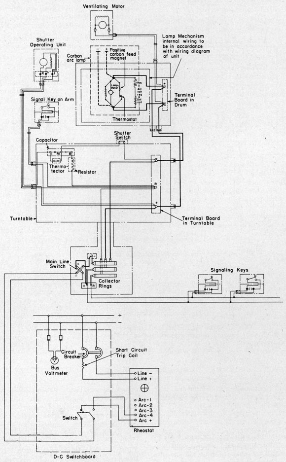
Fig. 10. Schematic Wiring Diagram of Ship's Installation Circuit
|
23
|
|
the negative carbon may not have been consumed as rapidly as the positive.
Insert the new positive carbon so that the crater end projects 9/16 inch from the obturator. When the carbon has been placed properly, lower the release lever, which returns the rollers to the operating position.
Insert a negative carbon in the negative head so that its end is separated from that of the positive carbon by approximately one-half inch. Return release lever, which causes rollers to grip the carbon.
Make sure that the carbons are centered in the head and do not make contact with the nose caps. The positive nose cap must be insulated from the electric circuit, or it will be burned by the arc.
After renewing carbon, the light should be turned on and operated for a three to five minute period until a normal arc is established. The main switch should then be opened, unless it is desired to use the light. This leaves the light with a full trim of carbons, with positive and negative carbons formed, and provides for normal operation for an emergency start. The critical period of operation is the first five minutes after a carbon renewal. During this time, a close watch should be kept of the arc and all lamp parts.
3. Starting the Arc
Turn the main switch to ON, The ventilating motor anti lamp motor start to run immediately, and continue to run as long as the lamp circuit is energized. The arc voltage regulator is energized and causes the negative carbon to advance and touch the positive carbon, completing the arc circuit. When the carbons make contact, the arc cur-rent jumps to between 125 and 200 amperes, and the arc voltage drops considerably. The voltage regulator then causes the negative carbon to retract and the arc current and voltage to reach stable values. During the arc-stabilization period, the arc voltage may drop to 40 or 50 volts; and then gradually builds up until the arc is stabilized. The voltage regulator then acts to maintain substantially constant arc voltage and arc length by advancing or retracting the negative carbon. The stable arc voltage depends upon the setting of the arc-adjusting knob only. The rheostat normally has no effect on the stable arc voltage. The thermostat system controls the positive-carbon feed to maintain the tip of the positive carbon at the focal point of the reflector.
The positive-carbon feed circuit is closed by a thermostat only when the arc has been held for |
|
sufficient length of time with a positive-carbon projection of less than 9/16 inch beyond the obturator. The automatic positive-carbon feed can function only to feed the positive carbon into the arc.
When the arc has been established, observe the position of the tip of the positive carbon with respect to the focal line on the arc-image screen. If it is slightly ahead or back of the line, do not disturb it, since the automatic feed will soon bring it into line. If it is more than 1/8 inch to the right of the line, the main switch should be turned to OFF, and the carbon reset to avoid the possibility of burning the obturator.
Do not start the lamp mechanism unless the carbons are properly placed, are firmly gripped by the feed rollers, and make good contacts with the current-carrying blocks,
4. Normal Appearance of Arc (Fig. 11)
When the arc is burning properly, the appearance will be as shown in Fig. 11. The "tail flame" which is shown extending above the positive-carbon tip lies in a vertical plane through the axis of the positive carbon. If the "tail flame" is observed to shoot off to one side or the other rather than toward the top of the drum, the alignment of the heads should be checked with the alignment gages and corrected. When operating properly, there will appear to be a ball of fire of high-intensity
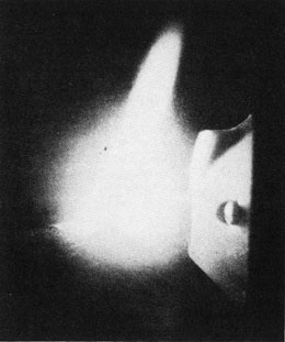
Fig. 11, Normal Appearance of Arc
|
24
|
|
burning within the positive-carbon crater. If the arc-current is too low, the appearance of this ball will not be so pronounced. If the current is too high, the arc will give an intermittent "sputtering" sound and the ball will appear to extend toward the negative carbon. Excessive current may also be indicated by a thin black tongue of soot appearing in the center of the "tail flame." Carbons which have not been kept completely dry will give unstable arcs.
5. Manual Operation of Lamp
Complete operation of the lamp by manual control may be accomplished in the following manner:
(a) Adjust the position of the positive carbon, so that its tip projects approximately nine-sixteenth inch beyond the obturator.
(b) Turn the main switch to ON, push in and rotate the positive-carbon crank slowly clockwise, at the same time pushing in and rotating the negative-carbon crank clockwise until the negative carbon strikes the positive carbon. Reverse the rotation of the negative-carbon crank and draw out the arc.
(c) Keep the positive-carbon crank rotating continuously and note the position of the positive-carbon tip on the arc-image screen. The positive carbon may be fed into the arc by holding in the positive-carbon-feed button as the positive-carbon crank is rotated. In this manner, the tip of the positive carbon may be maintained in its proper position, (touching the arc-image-screen focal line). The positive-carbon crank must be kept rotating whether feeding is desired or not.
(d) The negative carbon is advanced or retracted by turning the negative carbon crank (see Fig. 8). Since there are no meters at the searchlight, the operator should determine, by observation of the arc, when the arc current is at the proper value. The negative crank should be turned clockwise to advance the carbon, and counterclockwise to retract the carbon. The arc current will increase and the arc voltage decrease as the negative carbon is advanced. Conversely, the arc current will decrease and the arc voltage increase as the negative carbon is retracted. The operator should avoid feeding the negative carbon too far, as this will cause the arc to sputter excessively or to give off excessive black soot, both indications of excessive arc current.
6. Extinguishing the Arc
To extinguish the arc, turn the main switch to the OFF position. |
|
7. Precaution
(a) DO NOT ATTEMPT TO OPERATE THE CARBON-ARC LAMP WHEN EITHER CARBON IS SO SHORT THAT THE DRIVE ROLLERS WILL NOT ENGAGE IT.
When the positive carbon becomes so short as to slip its rollers, it will burn back toward the obturator. Since this will result in damage to the obturator, it is important that the carbons be renewed before the rollers fail to engage them.
(b) Always renew carbons by pairs.
(c) Be sure the lamp switch is OFF before changing carbons.
(d) Do not use broken or bent carbons.
(e) Be sure that the positive carbon does not touch its nose cap, and keep the nose cap free from dirt and carbon-dust deposits.
(f) Do not start the arc, unless the carbons are properly placed and are firmly gripped by the feed rollers.
(g) Do not operate the arc if the ventilating system does not function properly.
(h) Watch the arc-image screen to see that the tip of the positive carbon is projected on the inscribed focal line. Failure of the carbons to feed properly may cause damage to the heads.
(i) Do not look directly at the arc; use the peep sight.
C. Maintenance
1. Care
(a) General
After every extended run of the searchlight, and at least once each week for searchlights not in use, the interior of the drum and the lamp mechanism should be dusted and wiped clean. Particular attention should be given to rods, shafts, gears, contacts, and other closely fitting working parts of the mechanism which are dependent upon cleanliness for their free and proper functioning. Carbon dust and fragments of carbon should be blown or wiped out, and a close inspection made to prevent jams and similar difficulties caused by deposits of dust forming a gum on parts which are lubricated too liberally.
Each time the carbons are renewed, wipe off the front-door glass, thermostat lens, and thermostat window with a clean dry cheesecloth.
Never allow carbon stubs to remain in the lamp housing.
|
25
|
|
Clean all grease, oil, dust, and moisture from the insulation and electric-contact surfaces.
Clean the thermostat lens arid window, the arc-image screen, and the exposed surfaces of the lens system which projects the arc image. On these parts, use the cleaning procedure for reflectors or front-door glasses given on Page 37.
(b) Lamp Heads
(1) Reaming Heads
The positive and negative heads should be reamed before each recarboning with the reamers provided, to remove the material deposited by the preceding carbons. When using the reamers, the carbon feed rollers and contacts should be released by means of the negative-and positive-carbon release levers before the reamers are inserted. The positive-nose reamer should be inserted from the obturator end, and the negative-head reamer should be inserted from the back, or release-lever, end. Care should be exercised to prevent the cutting edges of the reamers from coming in contact with the rollers or contacts. Reamers should not be used while the heads are hot, unless absolutely necessary. However, if it is necessary to ream while the heads are still hot, the reamer should be kept turning continuously to prevent seizure by cooling and contraction of the metal parts.
(2) Brush Contacts
Clean the contacts in the lamp heads which carry the current to the positive and negative carbons by means of a piece of No. 00 sandpaper, wrapped once around a carbon stub. Examine the contacts to make sure that they are free to move up and down in their slides.
(3) Feed Rollers
Once a month, examine the feed rollers, and make sure the teeth are sharp enough to grip the carbon securely and not slip when the carbons are driven.
(c) Lamp Mechanism
Caution should be observed to keep the lamp side plates on tightly, and to prevent foreign matter from entering the lamp base.
(d) Carbons
The carbons should be stored in their containers until used. They should be protected from shock and handled carefully, to prevent breaking and chipping. The carbons should be protected from moisture, and carbons which have become damp should be dried out before using.
|
|
2. Cleaning
(a) Lamp and Lamp Mechanism
After each 50 hours of operation of the arc searchlight, and not less than once each quarter, remove the lamp from the drum, and brush and wipe thoroughly.
Use a small, clean paint brush to collect the carbon refuse from the thermostat lens and top of the lamp. Do not brush this refuse down along the sides or ends of the lamp; remove it.
Remove the lamp side plates, and clean up all excess oil with a soft cloth. Wash the lamp-head mechanism in alcohol or carbon tetrachloride to remove all graphite. Dry and recoat the wearing parts with a mixture of flake graphite thinned with kerosene. Blow out all parts of the lamp with an air hose or hand bellows, and lubricate according to procedure on this page.
After the lamp is reinstalled, check for the proper focus as described on Page 39. Then test for operation by the complete and noninterrupted burning of a pair of fresh carbons. Since all parts of the searchlights do not arrive at their normal working temperature until at least an hour has elapsed, this test should be continuous, and constitutes an endurance run for developing deficiencies which may not appear on the daily test of shorter duration.
3. Lubrication
(a) Lamp (See Fig. 12)
|
NOTE: Guard against oil or grease spotting the reflector, especially when the drum is in the vertical position.
|
Grease or oil should not be used on the heads. To keep them in good condition, apply a light coat of a kerosene and flake-graphite mixture at least once a week. This mixture should be used sparingly to prevent an excess falling on the reflector.
4. Parts Replacement
(a) General
A brief outline of the method used in removing and replacing various sections of the lamp follows.. The precautions and alignments outlined should be observed. The lamp must be removed from the drum to perform the following operations.
(b) Replacing Feed Rollers (See Fig. 2)
Replacing positive-feed rollers:
(1) Remove the 1 amp from the drum. (See Page 27.)
|
26
|
|
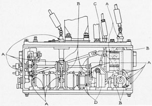
Fig. 12. Lubrication Chart for Lamp Mechanism
|
A-Apply clock oil, U.S.N. Symbol 1075, each month.
B-Brush with a good grade of light machine oil U.S.N. Symbol 1075, once in three months.
C-Oil with a good grade of light machine oil U.S.N. Symbol 1075.
D-Repack all ball bearings except those indicated by letter A with light grease, U.S.N. Spec. 14G1 once a year.
|
(2) Remove the cotter pin from the small-gear end (on the feed-roller shaft with two gears) and remove the small gear.
(3) Remove the cotter pin from the end opposite the gear (on the feed-roller shaft with only one gear).
(4) Grasp the remaining gears, and pull out the shafts until the feed rollers are released.
(5) Replace the old feed rollers with the new rollers, and push the shafts back into position.
(6) Replace the gears and cotter pins.
(7) Insert a carbon and test the action of the new rollers by rotating the positive-carbon crank and holding in the positive-carbon feed button.
Replacing negative-feed rollers:
The procedure outline d for replacing the positive feed rollers applies also to the negative feed rollers. However, since the negative-feed-roller shafts have gears on one end only, the cotter pins should be removed from the ends of the shafts opposite the gears, and the shafts pulled out by grasping the gears.
(c) Replacing Positive Obturator (See Fig. 2)
(1) Remove the lamp from the drum. (See Page 27.)
|
|
(2) Remove the obturator by removing the two screws at the front.
(3) Install the new obturator, and insert the screws loosely.
(4) Insert a carbon, and center the opening in the obturator about the carbon.
(5) Draw the screws up "snug."
(d) Replacing Positive-nose Cap
(1) Remove the lamp from the drum. (See Page 27.)
(2) Remove the positive-contact spring by pressing it down until it clears the upper boss of the positive-nose plate.
(3) Remove the four screws holding the positive-nose plate on the casting (care should be taken to avoid damaging the mica washers).
(4) Remove the nose plate with the nose cap and obturator.
(5) Remove the obturator by removing the two screws at the front.
(6) Remove the nose cap by removing the three screws holding it to the nose plate.
(7) Be sure that the mica washers are in place and install the new nose cap.
(8) Replace the obturator.
(9) Adjust the screws holding the positive-nose cap to the nose plate, so that the edge of the obturator is approximately 1/8 inch from the nose plate all around the edge.
(10) Center the obturator as outlined on Page 28.
(e) Replacing Positive Contacts (See Fig. 2)
(1) Remove the lamp from the drum. (See Page 27.)
(2) Remove the positive-contact spring by pressing it down until it clears the upper boss on the positive-nose plate.
(3) Remove the two screws holding the silver contact strips to the nose-plate support.
(4) Remove the screw holding the upper contact block to the contact strips.
(5) Bolt the contact strips tightly to the new upper contact block.
(6) Lift out the lower contact, and drop in the new lower block.
(7) Screw the contact strips firmly in place, and replace the positive-contact spring.
|
27
|
|
(8) Check the new contacts to see that they move freely in the guides.
(f) Replacing Negative Nose (See Fig. 2)
(1) Remove lamp from drum. (See this page.)
(2) Remove negative nose by taking out the two (2) screws that hold the nose to the casting.
(3) Install new nose, and insert the screws loosely.
(4) Insert a carbon, and center the half opening in the nose about the carbon.
(5) Draw the screws up "snug."
(g) Replacing Negative Contact
(1) Remove the lamp from the drum. (See this page.)
(2) Remove the negative nose.
(3) Drive out the pin that holds the nickel contact to the negative-contact lever.
(4) Remove the screw holding the contact to the underside of the casting.
(5) Remove lever, contact blocks, and contact strips, and disassemble to remove contact block.
(6) Replace the contact block, and reassemble by reversing the above procedure. (The block is self-aligning.)
(h) Replacing Thermostat Strips. (See Fig.2.)
(1) Remove the lamp from the drum. (See this page.)
(2) Remove the lamp side plate on the thermostat side.
(3) Remove the two screws that hold the wire guard around the strips to the insulation block.
(4) Remove the nuts holding the strips to the insulating base.
(5) Install the new strips, and reassemble by reversing the above procedure. (The distance between strips should be approximately 1/16 inch, and the thermostat points should be between 1/16 inch apart. The spacing of the points can be adjusted by bending the strips.
(i) Replacing Thermostat Lens (See Fig. 2)
(1) Remove the lens by removing the circular retaining spring from the bottom of the lens frame. (Care should be taken to catch the lens, as it will be free to drop when the spring is removed.)
(2) Ordinarily, replacement of the lens will not necessitate adjustment of the lens frame. However, if adjustment is required, see Page 29. |
|
5. Removing Lamp from Drum
(a) Make sure that the main switch is in the OFF position.
(b) Make sure that the drum is securely locked in the horizontal position, by means of the elevation stowing lock.
(c) Make sure that the turntable is clamped or locked.
(d) Open the rear door.
(e) Make sure that the signaling shutter is closed.
(f) Remove the carbons.
(g) Disconnect the lamp cables from the terminal studs in the lamp-control box.
(h) Turn the focusing screw five turns clockwise. Pull up the focusing latch at the rear of the lamp base, and thus unlatch the lamp from the focusing screw.
(i) Move lamp forward until lugs are released, lift lamp up, and remove it from the drum. When lifting it out, the lamp must be held high enough to allow projecting parts to clear drum. CARE SHOULD BE TAKEN TO APPLY LIFTING FORCE ONLY TO THE HANDLES OF THE CARBON-ARC LAMP.
6. Replacing Lamp in Drum
To replace a lamp in the drum, proceed as follows:
(a) Make sure the main switch is in the OFF position.
(b) Make sure that the drum is securely locked in the horizontal position by means of the elevation stowing lock and clamp.
(c) Make sure that the turntable is clamped, or locked.
(d) Make sure that the signaling shutter is closed.
(e) Insert the lamp in the drum so that the negative head will be toward the reflector (see Fig.13).
(f) Withdraw the focusing latch at the rear of the lamp base.
(g) Place the lamp in the lamp housing, well forward; then move it backward until stopped by the focusing screw.
(h) Push the focusing latch into the guides at the rear of the lamp until the slide latches the lamp to the focusing screw. Then turn the focusing screw five turns counterclockwise.
(i) Connect the negative (left-hand) cable to the negative terminal stud on the lamp box.
|
28
|
|
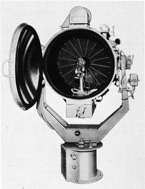
Fig. 13. Searchlight, showing Lamp in Position.
(j) Connect the positive cable (right-hand) to the positive terminal studs on the lamp box, making sure that the positive cable terminal does not interfere with the operation of the positive-carbon feed rod and is not touching the oil cup.
(k) Check the alignment of the heads with the gages.
(l) Recarbon.
(m) Check for proper focus as described on Page 39.
(n) Close and secure the rear door.
D. Adjustments
1. Alignment of Heads
Proper alignment of the heads is essential for satisfactory operation of the lamp. The alignment should be checked whenever the lamp has been removed from, and replaced in, the drum, and whenever the heads have been disassembled. The alignment should be checked and adjusted by inserting the gages and following the instructions as given in Fig. 14. This operation results in having the negative carbon strike the positive carbon 0.0781 inch |
|
below and 0.039 inch to the left of the center, and at an angle of 16 degrees.
2. Alignment of Obturator
The alignment of the obturator is accomplished by tightening the two screws that hold the obturator on the positive head (make sure they are snug). The positive obturator should never touch the positive carbon, and the carbon should be approximately centered in the opening of the obturator.
3. Arc Voltage Adjustment (See Fig. 8)
The arc-voltage adjustment may be made while operating the carbon-arc lamp in the drum. By removing the lamp housing cover the arc-voltage-adjusting knob is accessible and can be set to maintain an arc voltage of 65 to 70 volts during normal operation.
Whenever the arc-voltage-adjusting knob is being changed at the searchlight, the rheostat should be adjusted to hold the arc current at 75 to 80 amperes.
To increase the arc voltage turn the arc-voltage-adjusting knob clockwise. To decrease the arc voltage turn the knob counterclockwise. This knob should be moved only a notch or two at a time. One notch changes the arc voltage approximately one volt. Be sure the arc current does not exceed 80 amperes while this adjustment is being made.
NOTE: ALL ARC VOLTAGE MEASUREMENTS REFERRED TO ARE AT THE SEARCHLIGHT. IF THE VOLTAGE MEASUREMENTS ARE TAKEN ANYWHERE ELSE IN THE CIRCUIT, THE VOLTAGE DROP IN THE CABLES MUST BE TAKEN INTO CONSIDERATION.
4. Arc Brush-contact Pressure (See Fig. 2)
The spring pressure on the negative-carbon brush contact is set by adjusting the spring adjustment screw. If the spring adjustment is too tight, the negative carbon will be gripped excessively hard and may stick during operation of the arc. If it is too loose, a good contact surface cannot be maintained between the negative carbon and the brush contact. This adjustment should be set to give the maximum negative-carbon brush contact pressure possible without causing the negative car-bon to stick during operation of the lamp.
When the proper adjustment of the lamp is obtained, a pull of approximately 8 to 10 ounces parallel to the axis of the negative carbon is necessary to pull the carbon from the head with the feed rollers COMPLETELY disengaged from the carbon. For this adjustment with anew contact or an old contact
|
29
|
|
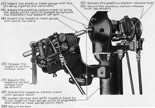
Fig. 14. Alignment of Heads
|
|
reamed smooth, the pull required to move the carbon from the head is less.
5. Adjusting Thermostat-lens Position (See Fig. 2)
The holes for the screws attaching the thermostat-lens frame to the negative head support are slotted so the lens may be moved toward or from the support column. This adjustment is made at the factory so that the beam of light from the lens will be in the space between the thermostat strips when the positive carbon projects 9/16 inch beyond the obturator. Moving the thermostat-lens frame toward the support column decreases the positive-carbon projection, and moving the frame away from the column increases the positive-carbon projection. A 1/16-in. movement of the thermostat-lens frame will change the projection approximately 3/32 inch. Measurement of the projection should be made immediately after the positive carbon has stopped feeding. This can be determined by noting the positive-head detent wheel and turning the lamp-control switch to OFF as soon as the wheel is released by the positive-carbon feed rod after a feeding period, and then measuring the projection. |
|
6. Adjusting Thermostat Contacts
Thermostat contacts are protected inside the lamp box, and normally require no adjustment. It should be definitely ascertained that the spacings are incorrect before any adjustment is made. The openings between the contacts should be between 1/64 inch and 1/32 inch. This spacing can be accomplished by bending one of the strips.
7. Adjusting Positive-carbon-feed Rod (See Fig.2)
When the positive-carbon-feed magnet is energized, the length of the positive-carbon-feed rod should be such that the detent at the upper end of the rod does not bottom in the recesses of the positive-head detent wheel but enters the recesses far enough to positively engage the teeth. This length is adjusted at the threaded portion of the rod where its lower end enters the insulated coupling.
The restoring spring on the rod for insuring disengagement from the detent wheel when the magnet is de-energized should be adjusted for a compression of 3/16 inch when in the raised position. This adjustment is made by shifting the clamp at the bottom of the spring on the rod.
|
30
|
|
8. Adjusting Arc-voltage Regulator Solenoid (See Fig. 5)
(a) Solenoid Plunger
This plunger should be centered in the solenoid core. Adjust by means of the slotted setscrews in the end of the rocker arm. The plunger should be free, with minimum clearance between set screws. The guide pin in the bottom of the plunger should extend through the guide spring at the bottom of the solenoid coil.
(b) Counterbalance
Adjust the position of the counterbalance on the rocker arm to hold the rocker arm horizontal with no pull on the tension spring and no voltage across the lamp terminals. Check the setting by applying the normal arc voltage (with negative carbon only in place but do not allow it to be fed into the obturator) and set the arc-voltage adjusting knob so that no motion of the negative carbon occurs. Tilt the lamp so that the positive carbon is vertical. If the counterbalance is set properly, no motion of the negative carbon should result. If the carbon is fed, the counterbalance is too far from the rocker-arm pivot. Move the counterbalance closer to the pivot, reset the arc-voltage-adjusting knob, and repeat the check for horizontal and vertical positions.
A retraction of the negative carbon when the lamp is moved from the horizontal to the vertical position indicates that the counterbalance is too close to the pivot and should be moved farther away.
(c) Arc-voltage Adjustment
The arc-voltage adjustment should be made with both carbons in place. Care should be taken to prevent the carbons from touching. If a bench adjustment is being made, the voltage applied to the lamp terminals should be controlled by an external series rheostat of approximately 100 ohms to carry three amperes. With this voltage set at the normal arc voltage of 65 to 70, the arc-voltage adjustment should be set so that no negative-carbon drive occurs. Movement of the adjusting knob one notch will vary the arc voltage approximately one volt.
(d) Pawls
Any attempt to make an adjustment or refine the existing pawl adjustment should be made only when positively necessary. It should be attempted only after a definite source of trouble has been located in this adjustment and after a complete understanding of the mechanism has been obtained. Considerable damage to the mechanism can be done if pawls in both the feed and retract gearing are allowed to engage the ratchets at the same time.
|
|
To adjust the pawls locate the normal rocker-arm position by pushing in the negative-carbon-crank coupling and noting that the normal-position pin is seated. The gearing should be turned so that the pawls are directly over the curved outer surface of the ratchets. When the pawls are adjusted properly, the slow pawls should clear the ratchets by 0.020 to 0.030 inch which will give a fast pawl clearance of 0.090 to 0.100 inch. This should not allow the arc voltage to vary more than plus or minus three volts from normal. A fast and a slow pawl are mounted on the same lever and cannot be changed independently with respect to each other. To change the clearance of the pawls, the pawl-lever-clamp screw and nut should be loosened slightly and the pawl lever shifted to give the desired clearance. The pawl lever should be tightly secured. Decreasing the pawl clearance decreases the variation in arc voltage necessary to cause motion of the negative carbon.
The slow-pawl adjustments should be set to cause motion of the negative carbon when the arc voltage varies from the arc-voltage-adjustment setting by two to three volts. With the slow-pawl adjustment set, one of the fast pawls should engage when the arc voltage is 10 to 20 volts from the arc-voltage adjustment setting.
The negative-carbon-pawl adjusting screws should be set to allow only sufficient travel of the rocker arm to cause the fast pawls to just seat in the bottom of the ratchet notches.
(e) Pawl Springs (See Fig. 5 and 6)
The pawl springs are placed between the pawls and the pawl lever to set the pawls against the pawl-lever stop pin and to allow reverse motion of the ratchet against the pawl. These springs require attention only in the most extreme cases. The springs should be no stronger than necessary to allow the pawl to be held against the stop pin. The slow-pawl spring must be compressed by the rocker-arm movement before the fast pawl can engage. If the slow-pawl spring is too stiff, the fast pawl will engage only at wide limits of arc-voltage variation from the arc-voltage-adjustment setting. The pawl springs are adjusted by means of the adjusting screws and lock nuts on the pawl lever.
(f) Ratchets
With carbons in place and normal voltage applied to the lamp terminals, it should be possible to easily stop either the fast or slow ratchets for either feeding or retracting by holding with a finger. The fast ratchets will be found to be slightly harder to hold than the slow but either one should turn freely and spin against its normal rotation. If the
|
31
|
|
mechanism appears to be tight and binding, the negative carbon-drive shaft should be disconnected to determine if the binding is in the mechanism or in the negative head.
The ratchets are of hardened steel and ground and fitted at the factory for each individual lamp. In case of damage or necessary replacement of ratchets, it is recommended that the lamp be returned to the factory.
E. Faults and Their Corrections
1. General
Before attempting the correction of any operating difficulties, it should be noted that the following circuit conditions exist:
(a) That all carbon-arc lamp d-c circuits are energized from the searchlight arc-supply voltage.
(b) That there are no fuses or circuit breakers on the searchlight.
(c) That all searchlight-arc power is switched ON and OFF at the main switch on the searchlight.
In order to facilitate the detection and correction of conditions resulting in operating difficulties, the following sources of trouble are listed and followed by the recommended method of correction.
2. Arc Current High or Low
If the arc current is high or low and the arc voltage normal, set the supply voltage to the proper value and reset the rheostat to obtain the proper current.
3. Arc Voltage High or Low
If the arc voltage is high or low and the arc current normal, set the supply voltage to the proper value and adjust the arc-voltage adjusting knob to obtain the proper voltage. Since this will change the arc current, it will be necessary to reset the rheostat to obtain the proper current.
This should be checked in the same manner as No. 2.
4. Positive Head Fails to Rotate
Push in the positive-carbon crank and turn; if the crank cannot be turned and the head does not rotate, check the positive-head-gearing for mechanical interference or foreign material in the gears. If the head does rotate, remove the lamp from the drum and proceed as follows:
(a) Apply 65-volt test leads to the lamp terminals (without carbons) and check to see that the lamp motor drives the worm gear. If the worm |
|
gear is not driven, check to see that the negative-carbon feed and retract pawls are not engaging at the same time (see Pawls, Page 30). Check to see that lamp motor will run with no load.
(b) Check the negative-carbon drive gearing for free operation (see Ratchets, Page 30).
5. Positive Carbon Does Not Feed
If this condition exists, hold in the positive-carbon-feed button.
If the carbon feeds: (1) Check the positive-carbon-feed rod for free operation and freedom from mechanical interference with the positive terminal; (2) By looking through the front door, check to see that the thermostat lens focuses the arc on the center of the glass thermostat window on the top of the lamp box when the positive-carbon tip is on the arc-image-screen focal line. If the arc is not focused on the center of the glass thermostat window, move the thermostat-lens frame until the focus is on the center of the window (make sure that the window is clean). If the focus is on the window, remove the lamp from the drum and proceed as follows:
(a) Check the POSITIVE-CARBON-FEED ROD adjustment (Page 29).
(b) Check to see that the positive-carbon-feed magnet armature (see Fig.2)is mechanically free.
(c) Check the THERMOSTAT CONTACTS for clearance (Page 29) and clean the contact surfaces.
(d) Apply 65 volts to the lamp terminals (without carbons). Short-circuit the thermostat by connecting a wire across the thermostat terminals (do not bend thermostat contacts closed). Check to see that the positive-carbon-feed magnet operates. If it does not, the magnet is probably open-circuited and should be replaced.
If the positive carbon does not feed, look through the dome-door glass and check that the positive-head detent-wheel rotation is arrested by the positive-carbon feed rod. If the wheel is not turning, proceed as follows:
(a) Check to see that the feed rollers are gripping the positive carbon.
(b) If the rollers are digging into the carbon, ream out the positive head.
(c) Inspect the feed rollers and replace them if the teeth appear to be worn.
(d) Check the positive-carbon brush contact for freedom of movement.
|
32
|
|
6. Positive Carbon Feeds Continuously
If the positive carbon feeds continuously, follow the instructions given in the second paragraph under "5. POSITIVE CARBON DOES NOT FEED."
7. Positive Carbon Is Held at Point Away from Arc-image Focal Line
(a) Check the positive-carbon projection (Page 29 ADJUSTING THERMOSTAT-LENS POSITION).
(b) Check the ARC-IMAGE SCREEN (Page 39).
(c) Check the FOCUS (Page 39).
8. Excessive Variation in Positive-carbon Projection
If the movement of the positive-carbon tip on the arc-image screen is greater than 1/16 inch from either side of the focal line, remove the lamp from the drum and check the THERMOSTAT CONTACT clearance (Page 29).
9. Negative Carbon Does Not Feed at Start
Check to see that the negative-carbon release lever is in the secured position, and then check to see whether the negative-carbon drive shaft is turning.
If the shaft is turning, check to see that the drive rollers are gripping the negative carbon. If the rollers are digging into the carbon:
(a) Ream out the negative head.
(b) Diminish the pressure on the NEGATIVE-CARBON BRUSH CONTACT (Page 28).
(c) Inspect the drive rollers, and replace them if the teeth appear to be worn.
(d) Check the negative-carbon-brush contact for freedom of movement.
If the shaft is not turning, remove the lamp and set it up for bench test, as follows:
(a) Check all ARC-VOLTAGE REGULATOR adjustments (Page 30), and check to see that with bus voltage applied across the lamp terminals, the fast-feed pawl engages and stops its ratchet.
(b) Check the PAWLS (Page 30).
(c) Check the solenoid-coil resistance (52 ohms).
(d) Check the solenoid-coil series resistor (150 ohms).
10. Negative Carbon Feeds Sluggishly
The negative carbon will feed sluggishly if the
|
|
pawls are slipping. The spacing or clearance of these pawls should be checked as on Page 30).
The trouble may also be in the serrated feed rollers. The rollers should be examined to make sure that the wheel points are sharp, and that they grip the carbon firmly. The negative carbon should be removed, and the contacts and negative nose should be examined for obstructions. These obstructions should be reamed out if they are observed. A damp carbon will also cause sluggish feeding, and the carbon should be examined and replaced if it is damp.
11. Negative Carbon Does Not Retract After Striking Positive Carbon
If the arc circuit opens, set the CIRCUIT BREAKER to a higher overload trip current (not exceeding 300 amperes). With the circuit breaker set at 300 amperes:
(a) Check the ALIGNMENT OF HEADS (Page 28).
(b) Ream the negative head.
(c) Remove the lamp from the drum and set it up for bench test. During this test, check all ARC-VOLTAGE-REGULATOR adjustments (Page 30) and check to see that the fast-feed pawl releases its ratchet before the test voltage is decreased to less than 10 volts above the normal arc voltage, and the slow-feed pawl releases its ratchet at a normal arc voltage between 65 to 70 volts. The negative carbon should be secured in position during this check.
(d) Check the PAWLS (Page 30).
(e) Check the solenoid-coil resistance (52 ohms).
(f) Check the solenoid-coil series resistor (150 ohms).
12. Arc Breaks Repeatedly
Check the arc voltage at the time the arc breaks. If the arc voltage is less than 65 volts, decrease the RHEOSTAT resistance (Page 34) trying the lamp to see if the arc will become established. If the arc voltage is greater than 70 volts turn the arc-voltage-adjusting knob counterclockwise a notch at a time until the arc voltage is between 65 to 70 volts. Then,
(a) If the arc holds, adjust the RHEOSTAT (see Page 34) to give an arc current of 75 to 80 amperes.
(b) If the arc does not hold, check the Alignment of Heads (Page 28) and ream the negative head.
(c) Remove the lamp from the drum and set it up for bench test. During this test, check all ARC-VOLTAGE-REGULATOR adjustments (Page 30) and
|
33
|
|
check to see that the fast-retract pawl releases its ratchet before the test voltage is increased to more than 10 volts below the normal arc voltage, and the slow-retract pawl releases its ratchet at a normal arc voltage between 65 to 70 volts. The negative carbon should be secured in position during this check.
(d) Check the PAWLS (Page 30).
(e) Check the solenoid-coil resistance (52 ohms).
(f) Check the solenoid-coil series resistor (150 ohms).
13. Arc Voltage Changes When Drum Is Elevated or Depressed
If the arc voltage should vary more than approximately five volts when the drum is elevated or depressed, the lamp should be checked. The circuit conditions should be measured before looking into the lamp. The counterweight in the lampbox should be checked, to make sure that it is tight and does not slip on its lever arm. The plunger in the center of the voltage-regulator coil should be checked in the elevated and depressed positions to make sure that it does not touch the inside of the coil. If this has become loosened, it should be centered and tightened.
There will be a slight change of approximately two volts when the drum is shifted from the horizontal position to the elevated or depressed position. This change is due to slightly different arc conditions and is not serious.
14. Excessive Arc-voltage Variation
If the arc voltage variation is excessive, proceed as follows:
(a) Check line voltage supplied to the rheostat for 125 volts.
(b) Check (a), (b), (c), and (d) of first section of "9."
(c) Spin the negative-drive rod to see that the action is free and that there is no binding. This should move the carbon back and forth freely.
(d) Replace carbons if variation continues.
|
|
(e) If excessive arc-voltage variation continues, a bench adjustment is necessary.
(f) Remove the covers from the side of the lamp. Make sure that no foreign matter is in the gearing.
|
CAUTION: Do not make any adjustment in the lamp box, unless absolutely necessary and unless another sources of trouble have been checked.
|
(g) Check the balance weight to make sure that it has not jarred loose, and that it is not rubbing or touching the side of the lamp box.
(h) With the lamp in the vertical position, make sure that the plunger in the center of the voltage-regulator coil is free and no binding occurs.
(i) Check the leaf spring on the bottom of the voltage-regulator coil plunger to make sure that it is functioning properly and that it bears against the bottom of the plunger.
(j) Push the negative manual-feed device into the neutral position and check the pawls for clearance. (See Page 30.)
Further checking should not be made, and the lamp should be returned to the manufacturer if excessive voltage variation continues after these checks have been made.
15. Arc Length Too Short
An approximation of the circuit conditions can be made from the appearance of the arc. This is an inaccurate method, but the arc and circuit conditions can be partially checked in the following manner: The arc length (from the tip of the negative carbon to the tip of the positive carbon) should measure approximately 3/4 inch on the arc-image screen. If this arc length varies 1/4 inch or more, the circuit conditions are not correct.
If the arc length is too short, the arc current is too high. Check as under (2) of Page 31.
16. Arc Length Too Long
If the arc length is too long, the arc voltage is too high, and should be checked as under (3) on Page 31.
|
34
|
PART III
|
|
RHEOSTAT
A. Description
The rheostat is connected in series with the arc (see Fig.15) and is usually, but not necessarily, in the negative side of the circuit. It acts as a ballast to steady the arc, and absorbs the difference between the voltage at the arc and the voltage of the line. A dial switch on the face of the rheostat permits variation of the amount of resistance in the circuit. A direction plate above the switch indicates that the handle should be moved counterclockwise to decrease the resistance and increase the current. The rheostat contains sufficient resistance to adjust the arc current to between 75 and 80 amperes for any bus voltage between 105 and 125 volts. (See Fig. 16.)
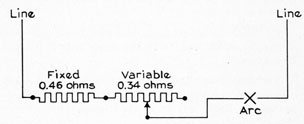
Fig. 15. Schematic Wiring Diagram
B. Adjustment
Adjustment of the rheostat is necessary for proper operation of the carbon-arc lamp. This rheostat permits adjustment of the arc current of the searchlight, and also compensation for changes |
|
in searchlight bus voltage. The rheostat setting should never be changed without noting immediately the effect of the change upon the arc current.
The rheostat should be used only to compensate for permanent changes in conditions on the line supplying current to the searchlight. It should not be used for making adjustments for transient conditions.
To increase resistance (decrease arc current), turn handle clockwise; to decrease resistance (increase arc current), turn handle counterclockwise. Since the rheostat is connected in series with the arc, the voltage drop across the rheostat is equal to the supply voltage, less the cable drop and the arc voltage.
The following items should be thoroughly under-stood and kept in mind:
(a) The voltage at the lamp is adjusted only by the arc-voltage adjusting knob at the lamp, and is not changed by any change in the bus voltage of rheostat resistance.
(b) If the arc-voltage-adjusting knob at the lamp is set at the desired position to maintain a normal arc voltage of 65 to 70 volts, a change in arc current caused by change in bus voltage must be corrected by adjustment of the rheostat only.
(c) If either the arc-voltage-adjusting knob or the bus voltage is changed, the arc current will also change. To correct for any change in arc current caused by moving the arc-voltage-adjusting knob or a variation in bus voltage, the rheostat setting must be readjusted to hold 75 to 80 amperes.
|
|
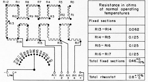
Fig. 16. Rheostat Wiring Diagram
|
35
|
PART IV
|
|
PROJECTOR
A. Description and Operation
1. General
The projector is the apparatus that controls the light from the lamp. The projector consists of the pedestal (the foundation), a turntable on which are mounted the trunnion arms, and the drum in which the lamp is installed.
2. Pedestal
The pedestal of the searchlight, which is secured to the searchlight platform, provides a mounting for the main switch, the train clamp, and the turntable. Within the pedestal are mounted three fixed brushes for collector rings, and two large ball bearings which allow the turntable to rotate continuously in train. The main switch is rotated by a handle that protrudes from the pedestal. This switch is reversible, and is marked ON and OFF.
3. Turntable and Arm.
(a) General
The turntable and arms which support the drum rotate in train on two large ball bearings within the pedestal. On the shaft of the turntable are mounted three collector rings for connecting power to the lamp, to provide a remote circuit for signal keys and to permit continuous rotation in train.
(b) Shutter Switch
The shutter switch is an indicating rotary switch with a snap action. This switch is mounted on the turntable just below the flat plate that opens to expose the terminal board. This switch must be thrown to ON to operate the signaling shutter mechanism by means of the arm key or remote keys.
(c) Train Clamp
The train clamp is mounted on the turntable just below the shutter switch. This clamp tightens when the rod is turned clockwise, and will clamp the searchlight in any position of train. There is a stowing lock to the immediate right of the train clamp. The stowing-lock pin engages one of three holes in the top of the pedestal. These holes are 90 degrees apart, and the pin maybe dropped into anyone of these holes, locking the searchlight, unless it is raised to the upper notch.
(d) Collector Rings, Thermo-Tector, Capacitor, Resistor Unit, and Turntable Wiring.
|
|
Collector Rings
There are three collector rings housed in the pedestal of the searchlight. The top collector ring is the negative ring; and the middle collector ring is the positive ring, as well as the neutral for the signal wire. The bottom ring is the second collector for the other remote signal wire.
Thermo-Tector
The Thermo-Tector is mounted just below the terminal board in the turntable. It is connected in the circuit as shown in the wiring diagram in back of book. This Thermo-Tector is a normally closed, heat-operated protective device which protects the signaling-shutter-operating mechanism.
Capacitor
A Pyranol-filled capacitor is mounted next to the Thermo-Tector. This capacitor has three poles, and is used in the circuit as two capacitors. One side of the capacitor is in parallel with the Thermo-Tector. The other side of the capacitor is in series with the resistor, and across the line that feeds the shutter-operating mechanism. This combination is to prevent fluttering in the shutter-operating mechanism.
Resistor Unit
The resistor unit is mounted just below the terminal board in the turntable. This resistor is connected in series with one side of the capacitor, and these two are connected across the lines feeding the shutter-operating mechanism.
Turntable Wiring
The turntable provides a mounting for a terminal board which has connectors for the lamp, and shutter-operating mechanism. (See wiring diagram in back of book.)
(e) Elevation Clamp
An elevation clamp is mounted on the upper part of the right trunnion arm. This elevation clamp tightens when turned clockwise, and it will hold the searchlight in any position of elevation (between stops). An elevation stowing lock is provided for locking the drum in the horizontal position (and also in the vertical position on some searchlights).
4. Drum
(a) General
The sheet-steel drum is trunnioned on needle
|
36
|
|
bearing on the top of the arms. The cables entering the drum pass up along the left arm, and then are looped into terminal tubes on the bottom of the drum. The ventilating-fan cable passes up the right side of the drum, and enters the ventilating-fan housing through a cable clamp.
Mechanical stops limit the elevation of the drum to 110 degrees, and the depression to 30 degrees. The drum can be clamped in any position (between stops) by means of the elevation clamp.
(b) Barrel
The barrel of the searchlight consists essentially of the shell to which is attached the shutter mechanism, and the front and rear doors. It includes the fan housing and lamp housing. On the sides of the barrel are attached two trunnions, which are supported by bearings mounted on the turntable arms.
(c) Lamp Housing
The lamp housing is a section welded on the bottom of the drum into which the lamp base fits. The lamp mounting lugs rest on grooves in the lamp housing.
(d) Rear Door and Reflector
The rear door is mounted on hinges welded to the left side of the barrel. It can be latched in the fully open position. The Stellite metal reflector is held in a recess in the rear door by means of clamps.
(e) Front Door and Dome Glass
The dome-glass is mounted in a hinged door which can be latched in the fully open position. This front door has four latches which hold it closed.
(f) Ventilating System
(1) General
A d-c shunt motor, mounted on top of the drum, drives an exhaust fan. The motor is connected across the arc terminal studs and is controlled by the ON position of the main switch. Air enters the baffled openings in the bottom of the lamp housing and at the sides of the drum, and takes the paths indicated in Fig. 9, passing over the inside of the dome-glass, the front of the reflector, and directly upward through the center, along the inner surface of the drum, and up through the head supporting column. All of the air is drawn through the fan at the top of the drum, and is exhausted downward over the left side of the drum.
(2) Ventilating Motor
The ventilating motor is a d-c shunt motor. It operates at 125 volts direct current when the
|
|
lamp is starting, and at 65 to 70 volts when the light is in operation. This motor is the G-E Model No. 5BC46A37, and is rated 1/6 horsepower.
(g) Iris Shutter
The primary function of the iris shutter is to maintain the drum substantially light-tight while the arc lamp is in operation. The iris shutter is mounted as a removable assembly between the drum and the front door, and is operated manually by turning the shutter handwheel.
(h) Signaling Shutter and Operating Mechanism
The signaling shutter is spring-actuated to close, and can be opened either manually by an operating handle on the forward right-hand side of the drum, or by means of remote and local signaling keys in the shutter-operating circuit.
A two-conductor cable from the remote signal keys enters the base through a bushing. This cable connects to the lower collector-ring brush and uses the positive brush as a neutral. The keys are connected directly across this incoming line and, if the shutter switch is at ON, the signaling shutter will operate when the key is closed. The shutter switch connects on to the negative side of the turntable terminal board, and feeds the shutter-operating unit through the capacitor and Thermo-Tector in the turntable. From this point, the line goes to the field and armature of the shutter-operating unit.
The shutter-operating mechanism consists of a limited-rotation d-c motor which is connected mechanically to the sector vanes of the shutter through gears. Connections to the armature are made through flexible leads. The 65-to 70-volt d-c operating voltage is supplied from the arc, and is conducted to the armature through the signaling keys. The shutter-motor field is not connected through the signal keys, but is energized whenever the shutter switch is at ON while the main switch is at ON. A capacitor and resistor unit is provided in the turntable to eliminate vibration of the motor armature. A latch is provided to lock the manual operating lever with the shutter in the open position.
(i) Positive-carbon Tube
At the center of the shutter vanes is a small insulated tube which projects a few inches toward the dome glass. This shield, or tube, provides a space into which a full-length positive carbon projects. The carbon should not touch the sides of this tube.
(j) Arc-image System (See Fig. 17)
In the arc-image system, Fig. 17, light rays from the arc at "A" are passed through the lenses
|
37
|
|
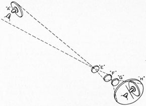
Fig. 17. Diagram of Arc-image System
"E," "F," and "G" and are projected on the ground-glass screen "H" which is located on the upper right-hand side of the drum toward the rear.
An upright image of the arc, approximately full size, is produced on the screen "H," and a black line marked on the glass indicates the correct position of the end of the positive carbon when it is at the focal point of the searchlight reflector.
The three lenses "E," "F," and "G" are mounted in a lens holder and form a unit known as the lens tube.
A dimmer operated by a small knob near the arc-image screen may be turned to vary the intensity of the image on the screen.
Over the screen is a hinged cover on the inside of which is a mirror. This cover may be adjusted so that an operator at the rear of the searchlight may see the arc image in the mirror.
(k) Peep Sight
On the center line of the right-hand side of the drum, directly opposite the arc, is a dense, colored-glass peep sight through which the arc (see Fig. 1) and the heads can be observed. The emission of light through the peep sight is limited by the density of the glass. When the peep sight is not in use, it should be covered by the peep-sight cover which is chained to the drum. This cover protects the glass and entirely eliminates the emission of light through the peep sight.
(l) Telescope Bracket and Beam Sights
An adjustable open sight and telescope mounting is provided on the upper right-hand side of the drum. On the right side of the mounting there is an open sight for directing the searchlight.
|
|
(m) Lamp Instruction Plate
A plate, bearing condensed operating instructions for the carbon-arc lamp, is attached to the right-hand side of the drum.
(n) Directing the Searchlight Beam
The searchlight is directed by an operator who stands behind, and slightly to the right of the, search-light. The operator directs the searchlight by releasing all stowing locks and clamps, and lining his open sights or telescope upon the object to be illuminated. The two handles on the back of the searchlight are for maneuvering the drum.
5. Signal Keys
A key is mounted on the searchlight, and two keys are provided for remote operation. The latter keys are provided with a U bolt for clamping on a pipe. The wires from the remote keys are connected to the searchlight through a cable entrance in the searchlight pedestal.
6. Drum Terminal Board
This terminal board on the searchlight is mounted in the front of the lamp box. This board provides a means of making the lamp and ventilation-motor connections.
B. Maintenance
1. General
Inspection, cleaning, and lubrication should be performed at regular intervals, even though the searchlight may not have been in operation. A thorough cleaning and dusting should be done quarterly.
2. Inspection and Cleaning
(a) General
The cleaning and inspection of the searchlight should be done at regular intervals, and should be done very thoroughly. If the searchlight is to operate under emergency conditions, it should be clean.
(b) Interior of Drum
Use a soft, dry cloth to remove accumulations of white deposits caused by the burning carbons.
(c) Cleaning and Polishing Reflector and Door Glass
The reflector and the inner surface of the door glass should be wiped off with a clean cheesecloth each time the lamp is recarboned.
|
38
|
|
After each extended period of operation of the arc, as soon as the reflector and the door glass have cooled, and at least once a week for lights not in use, the reflector and door glass should be cleaned as follows:
(1) Remove all dust with a blower, or with a soft clean brush or duster.
(2) Apply a suitable cleaning paste.
(a) For front-door glasses, prepare a cleaning paste by mixing three ounces of precipitated chalk with 1/2 pint of denatured alcohol. Thoroughly soak clean absorbent cotton in denatured alcohol, apply sufficient cleaning paste to the cotton, and rub carefully over the entire surface to be cleaned. Both sides of the front door glass should be cleaned.
(b) For Stellite reflectors, apply any standard Navy brightwork polish to the reflecting surface with absorbent cotton or a soft cloth.
(3) Before the deposit left by the cleaning paste or the brightwork polish has become dry, lightly rub or wipe the surface to be cleaned with clean dry cotton cloth (Bird's-eye) or lens paper, to produce a high polish. Do not wipe with a rotary motion, but move the cloth or lens paper radially outward from the center to the rim.
(4) After long use, and particularly when exposed to salt spray, the surface of a Stellite reflector may become coated in spots with a white deposit which cannot be removed by the use of brightwork polish. In this event, prepare a warm 5-per-cent solution of nitric acid (one part by volume of concentrated acid, and 19 parts by volume of water), and apply with absorbent cotton. Following this treatment, the reflector should be washed with hot water and dried with absorbent cotton. The use of nitric acid for cleaning Stellite reflectors should be unnecessary, except in unusual cases, and should never be used until routine cleaning methods repeatedly fail to remove the white spots.
|
PRECAUTIONS:
DO NOT ATTEMPT TO CLEAN THE REFLECTOR OR DOOR GLASS WHEN THEY ARE HOT.
NEVER USE RED ROUGE OR ANY OTHER POLISH CONTAINING IRON OR ABRASIVES.
NEVER ATTEMPT TO REMOVE SPECKS WITH A TOOL.
NEVER USE WASTE OR A CLOTH WHICH MAY SCRATCH OR OTHERWISE HARM THE ORIGINAL FINISH. BIRD'S-
|
|
|
|
EYE CLOTH AND LENS PAPER ARE THE BEST AND SAFEST MATERIALS TO USE, PROVIDED THEY ARE CLEAN AND FREE FROM OIL.
|
3. Lubrication
(a) Lubrication of Searchlight
The large ball bearings mounted in the base are grease-packed during assembly at the factory, and should require no further lubrication between overhauling periods of the searchlight.
Oil cups are provided at the top of the trunnion arms. Only S.A.E. No. 10 machine oil should be used in these fittings.
(b) Lubrication of Shutters
Once a month, apply a light coating of a kerosene suspension of colloidal graphite to the vanes, gears, and links of the iris shutter and gears, and bearings of the signaling shutter.
(c) Lubrication Precautions
Be sure to remove all old and gummy grease from the parts to be lubricated. Any foreign matter that has collected should be thoroughly cleaned off before lubrication. Always avoid excessive lubrication.
4. Parts Replacement
(a) Removing and Replacing Reflector
First, engage the stowing locks for the train and elevation of the searchlight. The reflector is exposed by removing 18 fillister-head screws on the back of the rear door and lilting off the rear door cover. The reflector can be lifted out, after removing the nuts from the clamps that retain the reflector. Be very careful not to scratch or mar it on the reflecting side.
The reflector can be replaced by slipping it inside of the six spacers, and replacing the clamps and nuts around its circumference. The reflector must then be lined up in accordance with the following procedure:
(1) Close the rear door, and tighten the clamps around the circumference of the reflector until the reflector is snug against the rear-door ring.
(2) Turn the arc lamp on, and direct the beam perpendicular to a screen or any convenient plane surface ten-to thirty-feet distant.
(3) Observe the shape of the beam projection on the plane surface. If it is round, no further adjustment is necessary. If it is not round, adjust as follows:
|
39
|
|
(a) Where the contour of the beam projection is inside the correct circular projection, release the pressure on the clamp opposite the inside contour by backing off the nuts.
(b) Where the contour of the beam projection is outside the correct circular projection, release the pressure on all clamps, except those opposite the outside contour, by backing off the nuts.
(c) Continue adjustments until the beam is round.
(4) When the reflector is lined up, replace the rear-door cover, and check the focus of the arc lamp (see this page).
(b) Removing and Replacing Iris Shutter
The iris shutter is a separate section between the door frame and the signaling-shutter frame. It can be removed by taking out the four cap screws that hold the door frame to the iris-shutter frame. After the door and door frame have been removed, the outside of the iris is available. The iris shutter can then be removed by removing the four cap screws that hold it to the signaling-shutter frame. These cap screws come through from the back of the flange. To replace, reverse this procedure.
(c) Removing and Replacing Signaling Shutters
The shutters are included in a separate section behind the iris. *This section can be removed by taking out eight cap screws holding it in place. Remove the front door by taking the pins from the hinges and lift it free. The shutter mechanism is removed in one complete section, and after the eight cap screws are removed, it is freed from the shutter-operating gearing simply by lifting it out.
When the shutter is replaced, it must be aligned with the shutter-operating gearing so that the handle on the manual shutter-operating handle is in the upper position and the shutters are approximately 3/8 inch from the fully closed position.
(d) Removing and Replacing Drum
Before removing the drum, make sure that the main switch is in the OFF position. Then disconnect and remove the lamp (see Page 27). Disconnect the arc cables from the drum terminal board, and take off the removable lugs. Loosen the gland, and pull the wires through. Next, remove the two cap screws on the top of each trunnion arm, and lift the drum from the trunnion arms.
Care should be exercised to keep the pivot bearings clean. Wrap them in wax paper or clean cloth as soon as the drum is removed.
* The stowing locks should first be secured.
|
|
The drum is replaced by reversing this procedure, making sure to center the drum between the trunnion arms. The drum should balance when replaced. After the wiring has been replaced and the bearing caps tightened, the bearings should be lubricated with a small amount of S.A.E. No. 10 machine oil through the oil cups.
(e) Removing and Replacing Dome Door Glass
The stowing locks should be secured. The entire front door should be removed and the door should be placed on a suitable mounting or surface. The 24 bolts that hold the retaining ring are removed next. This ring holds the door glass against the packing. After the ring has been removed, the asbestos packing should betaken out. The asbestos rope around the edge of the glass should be removed next.
The dome door glass can be replaced in the reverse procedure. Care should be taken to apply even pressure on the ring so that the dome-door glass is not cracked or stressed.
C. Adjustments
1. Arc-image Screen
The arc-image screen is adjusted properly when the focal line is at the means of the travel of the positive-carbon tip with the positive-carbon projection adjusted to 9/16 inch as described under "Adjusting Thermostat-lens Position" (Page 29) and with the lamp focused properly as described on this page under "Focus." During the normal cycle of positive-carbon feeding and burning off, the positive-carbon tip will move along the positive-carbon axis. This movement when viewed on the arc-image screen should not extend more than 1/16 inch either way from the focal line.
The arc-image-screen focal line may be adjusted to divide evenly the motion of the positive-carbon tip by adjustment of the four screws holding the arc-image-screen assembly to the drum. The assembly is seated in a mounting in the drum so that the screws directly opposite each other must be turned in opposite directions while making an adjustment; for example when tightening the top screw, the bottom screw should be loosened to move the arc image down. By tightening the front screw (loosening rear screw) the arc image will be moved to the left. All four screws should be snug but not clamped tightly after the adjustment is completed.
2. Focus
The focal point of the reflector is the point at which the light source must be located to obtain a
|
40
|
|
concentrated beam of parallel rays of light. The lamp is adjusted to this position by means of the lamp-focusing screw (see Fig.8) which is threaded into the lamp housing of the drum and connected to the lamp by a focusing latch attached to the lamp base. Removing this focusing latch from the guides frees the lamp from the focusing screw. The lamp-focusing screw has a lock collar which must be backed off when turning the screw and set up when the proper position of the lamp has been obtained.
Turning this screw clockwise moves the lamp away from the reflector.
Should it become necessary to refocus the lamp, loosen the lock collar on the lamp-focusing screw, see that the positive carbon projects 9/16 inch, note the focal length as shown on the surface of the reflector, and set the lamp by means of the lamp-focusing screw so that the end of the positive carbon is at the focal distance from the center of the front surfaces of the reflector. Set up the focusing-screw lock collar. When the lamp is in operation the image of the tip of the positive carbon should be on the line as described under ARC-IMAGE SCREEN. If the image of the positive-carbon tip is not on the arc-image-screen focal line, check the adjustment of the positive-carbon projection as described under ADJUSTING THERMOSTAT-LENS POSITION, and the adjustment of the arc-image screen as described on this page.
This focal adjustment may be checked by observing the beam at night. When the lamp is focused properly the beam will appear to consist of parallel rays.
If the lamp is too near the reflector the beam will spread. If the lamp is too far from the reflector the beam will converge into an "hour-glass" shape. The appearance of the beam should be judged from a distance.
To operate the lamp out-of-focus and spread the beam, loosen the focusing-screw lock collar and turn the focusing screw counterclockwise.
To put the lamp back in focus, turn the focusing screw clockwise until the tip of the positive carbon is on the arc-image-screen focal line as described under "ARC-IMAGE SCREEN." Lock the focusing-screw lock collar.
In the out-of-focus position, the positive-carbon tip will not be on the focal line. Its distance from the focal line should be observed frequently to make sure that it remains in the same position relative to the focal line and that the positive carbon is feeding properly. Do not disturb the adjustment of the arc-image screen from the true focal point when operating out-of-focus. |
|
3. Signaling Shutter Operating Mechanism
(a) Adjustment of Buffer-spring Tension
The buffer springs of the shutter-operating mechanism must be adjusted properly, to protect the shutter vanes. The adjustable-tension coil spring on the shaft should be placed on the fifth notch down from the top. The lower-buffer-spring tip should be adjusted until the shutter vanes close to approximately 3/8 inch from the fully closed position. With the spring compressed until the hand-operating lever is against its stop (or the buffer-spring housing), the shutter vanes should be almost closed-about 1/32 inch from the fully closed position.
The upper-buffer-spring tip should be adjusted until the vanes are almost in the fully open position when the hand-operating lever just touches the tip. When the buffer spring is compressed and the hand operating lever is against the solid stop, the vanes should be just beyond the full open position.
(b) Adjustment of Shutter-operating-mechanism Armature
The coil spring should be tightened to the top notch, and the buffer springs should be loose. The shutter-operating mechanism should be stopping when the lever reaches the buffer-spring housing. The partial-rotation motor of the shutter-operating mechanism is damped out at this point, so that no excessive stress is applied on the stops when the shutter is operated at high speed. If the buffer-spring housing cannot be adjusted through its threads, the armature of the shutter-operating motor should be replaced. Remember that the limits of the vane closing must be met when the adjustment is made.
D. Faults and Their Correction
1. Signaling Shutter Operating Mechanism
If the signaling shutter does not operate when the key is depressed, check to see that the shutter is not held open by the latch provided for that purpose.
If the latch is free and the key still does not operate the shutter, examine the contacts on the key, to make sure that they close the circuit.
After this check, if the shutter still does not work, the electrician should "ring-out" the circuit with a bell set. This circuit should be checked in accordance with the wiring diagram furnished.
|
41
|
|
2. Failure of Shutter to Operate
(a) See that the shutter operates freely by moving the operating handle manually. Locking or binding of the shutter indicates mechanical interference. Check to see that the mechanism is clamped on the support bars in such position that the motor-shaft gear properly meshes with the shutter gear (inside drum) and that the motor shaft is not binding where it enters the drum. The motor gear may be unmeshed from the shutter gear and by trying the shutter vanes, check that they operate freely. Binding or interference may be found in the shutter bearing.
|
NOTE : On re meshing the motor and shutter gears, make sure that with the closed shutter stop spring fully compressed by the operating handle there is a slight clearance between the vane edges.
|
(b) Check to see that the d-c supply is conducted to and through the shutter switch.
(c) Check to see that the supply is conducted to and through the signaling key, the searchlight collector rings, the Thermo-Tector and to the shutter motor armature and field.
3. Sluggish or Erratic Operation of Shutter
(a) Check as shown under Section 2.(a)
(b) Try various positions of the shutter-closing spring.
(c) If excessive hum or vibration of the motor armature is noticed, check the capacitor and resistor unit (capacitor 8/1 mu f, resistor 10 ohms).
(d) Burning and sticking of the signaling key contacts indicates a faulty capacitor in the key base. Check for 2 mu f.
INSTALLATION
A. Unpacking the Searchlight
To unpack the 24-in, searchlight, first remove the top from the packing box. Next, remove the sides and ends. Be sure to avoid striking the searchlight with the unpacking tools.
Inside the packing box is a smaller cardboard box containing two signal keys for remote operation. These keys should be removed, and the packing paper that is over the searchlight should be removed. The searchlight can now be completely removed from the packing, by removing the two packing nuts which hold the searchlight on the wooden platform.
|
|
B. Installation of Searchlight
The installation plan bound at the back of this book gives the information necessary for installation of the searchlight.
C. Installation of Rheostat
The rheostat should be mounted in a convenient place below deck. The mounting dimensions and necessary wiring are shown on the installation plan bound at the back of this book.
D. Installation of Signalling Keys
The remote signaling keys are installed by clamping them on a pipe, in a suitable location, by means of the U bolt provided with the key. The wiring is connected to them through the bushing at the bottom of the box. The signal key may also be clamped to a flat surface if so desired. The key will operate either in the horizontal or the vertical position.
The two-conductor cable from the remote signal keys enters the searchlight base through a bushing. It connects to the lower collector-ring brush and the positive brush for the neutral. The keys are connected directly across this incoming line, and if the shutter switch is at ON, the signaling shutter will operate when the key is closed. The wiring diagram shown on Fig. 10 and the installation plan bound at the back of this book give the details of the circuit.
E. Testing After Installation
When the searchlight has been completely installed and wired, it is necessary to install a voltmeter and ammeter at the searchlight to check the circuit conditions. The rheostat and the arc-voltage adjusting knob should be adjusted until 65 to 70 volts and 75 to 80 amperes are obtained when the arc is operating.
After the searchlight has been properly set, the instruments should be removed and new carbons inserted. When the new carbons are installed, the searchlight should be operated continuously for one complete trim of carbons. During the run, the car-bon position on the viewing screen should be checked frequently.
If the searchlight functions properly throughout this run, the carbon stubs should be removed and discarded, and new carbons installed. After new carbons have been installed, the searchlight should be operated for about five minutes to form the craters. The signaling shutter should be checked for operation by the key mounted on the searchlight and by the remote keys. The searchlight is now ready for quick operation.
|
|
|