Routine tests are made on all engineering installations to insure against failure of the equipment. Standard instructions are always issued for each type of equipment and those concerned are responsible for seeing that tests are made when and as prescribed.
Accurate records of all inspections and tests must be kept. Accurate records of all failures and repairs must also be kept, including general remarks that will be helpful to anyone else who must work on the equipment later. There are logs, card indexes, and other records prescribed to cover these points.
Routine tests and inspections are made daily, weekly, monthly, quarterly, semi-annually, and annually. In general, these inspections and tests are made:
Daily.-To test for proper operation and signs of future trouble. An experienced man can frequently anticipate failures by the slight changes noted during the daily tests of equipment. Daily checks are also of help in preventing the deterioration of idle equipment from lack of use.
Weekly.-To test more thoroughly for proper operation than is possible each day. On weekly tests, lubrication, motor speeds, cleanliness, and safety devices receive special attention.
Monthly.-To check the more inaccessible features. In some equipment, tubes are replaced monthly. Antennas are checked.
Quarterly.-To insure proper maintenance of major items such as tubes, armatures, antennas. Receiver sensitivity is measured so that the need for repair or realignment may be accurately determined.
Semi-Annually and Annually.-To determine the need for major repairs. The most inaccessible parts are checked and are given minor routine overhauls.
When inspecting and testing, the things to be checked on the various items of equipment are as follows:
RECEIVERS
Cleanliness Mechanical Condition Connections, switches, etc.
Operation, on each band Sensitivity Selectivity Noise level
162
TRANSMITTERS
Cleanliness
Operation
Mechanical Condition
Frequency Stability
Connections, switches, etc.
Keying
Oscillation
Normalcy of meter readings
On all bands or crystals
Output to antenna
MOTOR GENERATORS
Cleanliness
Operation
Lubrication
Voltage output
Mechanical condition
Sparking
Vibration and noise
Overheating
DIRECTION FINDERS
Cleanliness
Operation
Mechanical Condition
Sensitivity
Including loop operation
Selectivity
Deviation changes, sense features
Noise level
Balance
UNDERWATER SOUND
RECEIVER
Same as receivers
Tuning
To resonate with projector
RANGE INDICATOR
Cleanliness
Safety Interlocks
Speed
Mechanical condition
HOIST-TRAIN SYSTEM (including remote control)
Hoist-lower
Limit switches
Training
DRIVER
Same as transmitters
Tuning
Keying relay
To resonate with projector
Connect-disconnect relay
ANTENNAS
Cleanliness
Mechanical condition
Resistance to ground
Insulators
Leakage, or concentric transmission lines
Wires, splices, shackles, etc.
Lead-ins
Make all routine tests and inspections called for by the instructions. Keep accurately all required records.
163
SPARE PARTS
Exact duplicate replacement spare parts and spare vacuum tubes are always furnished, so that anything that is likely to fail or wear out may be replaced quickly when this becomes necessary. Accurate records must be kept of the parts on hand and the place in which parts are stored.
Whenever a part or a tube is used, a replacement for it should always be ordered immediately.
4.2 Frequency Measurements and Calibration
Transmitters and receivers must be set on the assigned frequency accurately if continuous and reliable communications are to be maintained.
The frequency tolerances, that is, the amount of deviation from assigned frequencies that will be allowed, are prescribed by international treaty. As far as ships are concerned, these tolerances are:
Frequency Band:
Percent assigned freq. allowable error
10-550 kcs
0.1
550-1500 kcs (broadcast)
20 cycles
1500-4000 kcs
0.05
4-30 mc
0.02
Actually, frequencies can and should be maintained much nearer the assigned values than the figures given above indicate.
The frequency measuring equipment found aboard ship and elsewhere is based on the oscillations of a very accurate quartz crystal, usually operating at 100 kilocycles. Some form of heterodyne frequency meter and associated equipment is used with the crystal calibrator. In older equipment the basic units may be separate. In newer equipment all the parts are mounted in one cabinet.
Space does not permit a detailed description and explanation of the operation of the many equipments in use. The instruction book on each particular installation must be carefully studied before the equipment is used. There are minor differences between models.
In general, all frequency measuring devices used aboard ship are the same, containing a crystal controlled calibrator, a heterodyne frequency meter, a multivibrator, and a combination detector-amplifier. There will be a power supply and other miscellaneous parts, depending on the equipment.
When comparing frequencies, the heterodyne or beat method is used. In this method the standard signal and the one being measured are combined, and one of the two is varied until there is no frequency difference between them. This condition is known as "zero" beat. The term "zero beat" arises from the fact that as the frequencies are
164
brought closer and closer together, the audible signal, or beat frequency, slowly passes to very low audio frequencies and then disappears when the two frequencies are identical.
The crystal oscillator is an accurately ground quartz bar having a natural frequency of vibration of 100 kcs. It also produces a wide range of harmonics of 100 kcs. It thus provides signals at fixed points in the frequency spectrum for calibration or measurement.
The heterodyne frequency meter is a variable oscillator to produce many frequencies. It is quite stable but must be calibrated with the more stable crystal and checked with it frequently.
The multivibrator produces signals that are very rich in harmonics. When controlled by the crystal, it furnishes many frequencies for calibration or checking. It further serves to split up the crystal frequencies, thus providing accurate signals every 10 or 20 kcs. to fill in between the points provided by the crystal.
Ordinarily, two methods may be used in comparing signals. The frequency meter output may be led into a receiver for combination with the signal being measured, or for calibration purposes.
The signal being measured may also be led into the amplifier-detector combination of the frequency meter and the comparison made in the meter.
The frequency meter instruction book should be studied most carefully. It is especially important to know how to interpolate accurately, that is, to find from the meter calibration curves or tables, the frequencies corresponding to settings between the basic settings of the meter.
Hasty, careless, or improper interpolation in using a frequency meter can nullify all the care taken to produce an accurate instrument. Poor interpolation may result in transmitters being set off frequency or receivers calibrated so inaccurately that they cannot be set on frequency from the calibration data.
CALIBRATION
Transmitters and receivers are calibrated so that they may be set on desired frequencies without the necessity of checking the settings with measuring equipment each time.
In calibrating, the settings of the controls of the equipment necessary to tune it accurately are recorded. If the necessary precautions are observed, the equipment may be tuned to the frequency by resetting the controls to the values obtained earlier.
Calibration may be general or specific. In general calibration, the settings for several frequencies spread over the range of the equipment are obtained. Curves are then plotted to include the several points obtained. By referring to the curves, settings may be read off for any frequency within the range.
165
Since it takes time to read values accurately from the calibration curves, specific calibration is used for the frequencies required most often. In specific calibration the settings for a given frequency are recorded, and a list is made up of the commonly used frequencies with the settings for each of them.
It is desirable to have complete calibration curves on each piece of equipment as well as specific settings for the frequencies usually used.
In frequency measurements and comparisons, exactness and accuracy are relative. Even with the most elaborate, practical precautions, it is seldom possible to set and maintain a frequency measuring apparatus exactly accurate. To make sure that frequency meters are accurate, they must be compared frequently with a standard.
The standard frequencies, very accurately maintained, are transmitted regularly by WWV, the Bureau of Standards Station at Washington, D. C. The schedule of WWV transmissions is published from time to time. It may also be obtained from any Federal Communication Commission, Radio Inspectors Office.
If it seems desirable to have some particular frequency checked, arrangements may usually be made to have a check made by a nearby shore station. In some ports such as Baltimore, Md., and San Pedro, Calif., Federal Communications Commission monitoring stations may also be asked to check a frequency.
MISCELLANEOUS
It is impossible to build equipment that will not change frequency slightly, or "drift", as it warms up, although some modern equipment is remarkably stable in operation.
Consequently, when calibrating, care must be taken to let receivers warm up for at least an hour and preferably two hours before making measurements.
In transmitters there is frequently some provision for heating the critical oscillator circuits continuously so as to maintain frequency stability. These heating arrangements must be kept working as designed at all times if the exact frequencies desired are to be obtained.
It is possible for an extremely strong signal to drag or lock a weaker oscillator into step with it. Although this will seldom happen with the equipment supplied, it should not be overlooked.
Most frequency measurements are made by heterodyning two signals to zero beat, which means that just before the zero beat or dead point is reached, the beats are very low frequencies.
The human ear is not a particularly good indicator of very low frequencies. Consequently, care must be taken to be sure that actual zero beat has been reached, and not a point on one side of it.
166
At low radio frequencies, the zero beating is complicated by the fact that a large movement of the tuning control is necessary to vary the signal. To overcome the uncertainty of the exact setting, sometimes a definite 500 or 1000 cycle audio oscillator is provided as an auxiliary. This auxiliary is used to allow tuning a definite amount on either side of the desired zero point. The two readings on either side are taken, and the midpoint gives the desired zero beat setting.
In checking frequencies and in calibration, as in so many other things, the basic principles must be understood, the instructions furnished must be studied, and thought must be given to each problem. The blind following of a set of rules will not inevitably produce the desired results.
4.3 Radio Direction Finders
Radio direction finder equipment differs from other equipment in that the antenna, or loop, is a critical element. This means that in addition to problems connected with the radio receiver and electrical equipment, there are also loop problems.
It is impracticable to go into the theory and detailed operation of direction finders here. It may be helpful, however, to discuss a few of the major points involved and some of the troubles that arise. In the following discussion, radio direction finder will be abbreviated DF.
The three factors affecting DF operation aboard ship are:
1. Excessive deviation, particularly as the frequency is increased, with the ultimate absence of any "minimum" or with all bearings reading approximately fore-and-aft.
2. Inability to obtain proper "balancer" action, especially at higher frequencies, with the resultant lack of a well defined minimum.
3. Difficulty in keeping the deviation constant, i. e., deviation changes between calibrations.
Deviation is defined as the difference between the observed radio bearing and the corrected radio bearing. There are several possible causes of deviation, the most important being voltages induced in the DF by near-by metallic objects, such as loops that have current flowing in them.
Ordinarily, deviation is quadrantal, that is, at 0, 90, 180, and 270 degrees relative to the ship's head, there will be points of zero deviation. The zero points will be exactly on these bearings and the deviation curve will be symmetrical only if the DF is so located that the ship is symmetrical around it. Ideally, this would require the DF to be amidships on the center line.
The wave on which a bearing is to be obtained strikes the ship, as well as the DF loop. The wave, in striking the ship, induces currents in the ship's structure that produce flux influencing the voltages generated in the DF loop.
167
If, under such circumstances, the loop is trained to be normal, or perpendicular, to the incoming wave, there will still be a "residual" signal heard due to the induction from the ship's structure. If the DF loop is now moved off of the true wave direction enough to give a minimum signal, the number of degrees the loop is moved is the deviation.
Balancing, as described above, will never result in an absolute minimum because of the phase relations between the wanted and unwanted voltages in the loop;
A nondirectional vertical antenna is used to put a balancing voltage of proper phase into the DF so that a good minimum can be obtained. The amount and phase of the voltage required is adjusted by means of a "balancer" device in the DF receiver.
When the balancer settings are plotted they will usually be found to be semi-circular, instead of quadrantal like the deviation curves.
The vertical antenna also serves as a source of voltage to change the DF characteristics so that "sense" or unilateral bearings can be taken.
In considering breaking up existing closed loops in the ship's structure, it is well to remember that fore-and-aft loops may be helpful, while closed loops athwartships are most harmful.
Closed loops formed by stays, etc., not more than two DF loop diameters away from the loop, should be broken up by the insertion of insulating materials.
"Corrector wires" are installed to make complete loops of parts of the ship's structure or rigging. The area inclosed by the entire corrector loop is important; the length of the corrector wire is not.
In surveying an installation, if the maximum deviation at 300 kcs is 6 degrees or less, it is usually inadvisable to use a corrector wire. If the deviation is between 10 and 20 degrees, a corrector loop of 100 square feet should suffice. If deviation is between 20 and 40 degrees, about 150 to 200 square feet of corrector loop will be required.
The area under a corrector wire and in the corrector loop need not be clear of miscellaneous objects.
Ordinarily, the coupling of a corrector loop to the DF is determined by swinging ship and trying the effect of the loop for different corrector wire positions, until deviation is reduced to between 5 and 10 degrees. It is seldom desirable to eliminate deviation. More than one corrector loop may sometimes be required. The plane of the corrector loop must be fore-and-aft.
Corrector loops that are small and tightly coupled to the DF loop are apt to reduce DF sensitivity.
Perfect, low-resistance connections must be made and maintained at both ends of each corrector wire. Also, the wire must not be allowed to sag, sway, or move or the calibration and deviation will vary erratically.
168
DIRECTION FINDER TROUBLES
It is most important to examine the ship structures, and rigging carefully before attempting to calibrate a DF, to make certain that all objects, especially those near the DF, are secured in place.
When DF bearings become erratic, the first thing to look for is a change that has been made in the structure, rigging, or stowage of material near the loop. A new receiving antenna, for example, incautiously erected less than about 100 feet from the loop, will upset the calibration markedly.
Ideally, all antennas should be open when the DF is being calibrated and whenever it is used, but practically this is not feasible. Receiving antennas and high frequency antennas are normally closed during calibration and low frequency antennas are opened. The conditions during calibration must be duplicated whenever the DF is used.
There are at least two sources of DF bearing error, or difficulty in taking bearings, that are beyond control. These are known as "night effect" and "coastal effect".
Theoretically, and actually during daylight, it is ordinarily true that bearings are taken on a "ground" wave. At night, when refraction or reflection from the ionosphere increases, the resulting "sky" wave may combine with the "ground" wave to produce erratic or erroneous bearings, cause fading signals, etc. This resultant effect is generally known as "night effect". It is most disturbing during the periods from about 1 hour before to 1 hour after sunrise and sunset.
Night effect is not inevitable every day and on every frequency. It must not be confused with operator errors or carelessness, or upkeep and maintenance failures.
If the ground wave being used has to travel overland for some distance before it passes over water, there may be a bending of the wave at the land-water boundary. The effect is especially noticeable when the angle between the wave and the coast line is small. The error in bearing resulting from this bending action is known as "coastal effect".
DF receivers are subject to all the troubles of any receiver. In addition, they are also subject to difficulties arising from poor or loose connections around the loop input and balancer circuits.
The table given below gives a few of the troubles peculiar to DF equipment.
Symptom
Procedure or cause
Erratic bearings
1. Operator's mistake.
2. Crane, boom, davit, or railing moved.
3. DF loop or scale loose and shifting.
4. Night effect.
169
Symptom
Procedure or cause
Bearings of all stations the same
1. Check loop for continuity. 2. Check lead-in, grounds, screening, and loop tuning condenser. 3. Check antennas for one closed.
Bearings incorrect on certain frequencies: when signals are strong; or intermittent.
1. Check circuit from loop to receiver, especially the collector rings. 2. Poor ground connection. 3. Nearby closed antenna or other conductor. 4. Loops formed by rigging conducting only when wet. 5. Night effect.
Minima not 180 degrees apart.
1. Antenna effect due to pickup not through loop. Check all other possible sources of signal. 2. Check loop center ground, if any. 3. Nearby antenna resonant.
Indefinite minimum, lack of balance.
1. Wrong size vertical antenna. 2. High resistance balancer or vertical antenna circuit. 3. Direct receiver pickup, check shielding. 4. Receiver not properly balanced or tuned. 5. Poor loop ground, or other high resistance contact in input circuits.
Loop shorted
1. Moisture formed by condensation in loop housing or pedestal on collector rings. 2. Aluminum oxide from assembly has fallen on collectors. 3. Mechanically shorted lead.
Weak signal
1. Bad tubes. 2. Defective receiver. 3. Collector loop coupled too tightly. 4. Loop housing insulator painted over.
Direction finders frequently do not operate well aboard ship and, unfortunately, each ship presents a separate problem. All information that can be obtained on direction finders and direction finder problems should be carefully studied whenever the opportunity arises.
Even today, the solutions to all direction finder problems are not known.
170
4.41 Conversion Table
Multiply
By
To get
Amperes
1,000,000,000,000
Micromicroamperes.
Amperes
1,000,000
Microamperes.
Amperes
1,000
Milliamperes.
Cycles
0.000,001
Megacycles.
Cycles
0.001
Kilocycles.
Farads
1,000,000,000,000
Micromicrofarads.
Farads
1,000,000
Microfarads.
Farads
1,000
Millifarads.
Henrys
1,000,000
Microhenrys.
Henrys
1,000
Millihenrys.
Kilocycles
1,000
Cycles.
Kilovolts
1,000
Volts.
Kilowatts
1,000
Watts.
Megacycles
1,000,000
Cycles.
Mhos
1,000,000
Micromhos.
Mhos
1,000
Millimhos.
Microamperes
0.000,001
Amperes.
Microfarads
0.000,001
Farads.
Microhenrys
0.000,001
Henrys.
Micromhos
0.000,001
Mhos.
Micro-ohms
0.000,001
Ohms.
Microvolts
0.000,001
Volts.
Microwatts
0.000,001
Watts.
Micromicrofarads
0.000,000,000,001
Farads.
Micromicro-ohms
0.000,000,000,001
Ohms.
Milliamperes
0.001
Amperes.
Millihenrys
0.001
Henrys.
Millimhos
0.001
Mhos.
Milliohms
0.001
Ohms.
Millivolts
0.001
Volts.
Milliwatts
0.001
Watts.
Ohms
1,000,000,000,000
Micromicro-ohms.
Ohms
1,000,000
Micro-ohms.
Ohms
1,000
Milliohms.
Volts
1,000,000
Microvolts.
Volts
1,000
Millivolts.
Watts
1,000,000
Microwatts.
Watts
1,000
Milliwatts.
Watts
0.001
Kilowatts.
171
4.42 Decibels
In radio and electrical problems it is frequently necessary to know the circuit gain, loss, or other ratios. For such purposes the most convenient unit to use is the decibel, which is abbreviated db.
Most communication circuits and devices may be considered as electrical networks having two input and two output terminals. The ratio of output power to input power, usually expressed in decibels, is a measure of how the device affects the transmission of energy through itself.
The formula for this ratio in decibels is:
Ndb = 10 log10P1/P2
P1 = power output. P2 = power input.
When we are interested in voltage or current ratios, we can find the number of decibels by the formulas:
Ndb = 20 log10I1/I2 Ndb = 20 log10E1/E2
E1 and I1 are outputs. E2 and I2 are inputs.
The formulas for voltage and current ratio assume that the input and output impedances are equal. If the impedances are not equal, it is more convenient to compute the equivalent power from the voltage or current and the corresponding impedance, and then convert the power ratio obtained into decibels.
If the ratio of output to input power is greater than 1, there is a gain in the device. If the ratio is less than 1, there is a loss. Gains are expressed in plus db and losses in minus db. Since the decibel is a logarithmic unit, the gains and losses in a complicated circuit can be added algebraically to determine the over-all effect of the circuit.
It is useful to remember a few facts about decibels. For example, a change of 3 db just about doubles or halves the power being measured. Also, 0 db means no change, 10 db equals 10 times, 20 db equals 100 times, 30 db equals 1000 times the power, and so on.
It must be remembered that, unless a ratio only is involved, decibels have no real meaning. For example, it is meaningless to say that an output signal is plus 10 decibels, because no standard reference level is specified. With a standard level of 6 mw, the plus 10 db signal becomes intelligible and is equal to 60 mw.
510493-43-12
172
DECIBELS
Minus (-)
db
Plus (+)
Voltage ratio
Power ratio
Voltage ratio
Power ratio
1.0000
1.0000
0
1.000
1.000
.9441
.8913
.5
1.059
1.122
.8913
.7943
1.0
1.122
1.259
.8414
.7079
1.5
1.189
1.413
.7943
.6310
2.0
1.259
1.585
.7499
.5623
2.5
1.334
1.778
.7079
.5012
3.0
1.413
1.995
.6683
.4467
3.5
1.496
2.239
.6310
.3981
4.0
1.585
2.512
.5957
.3548
4.5
1.679
2.818
.5623
.3162
5.0
1.778
3.162
.5309
.2818
5.5
1.884
3.548
.5012
.2512
6.0
1.995
3.981
.4732
.2239
6.5
2.113
4.467
.4467
.1995
7.0
2.239
5.012
.4217
.1778
7.5
2.371
5.623
.3981
.1585
8.0
2.512
6.310
.3758
.1413
8.5
2.661
7.079
.3548
.1259
9.0
2.818
7.943
.3350
.1122
9.5
2.985
8.913
.3162
.1000
10.0
3.162
10.000
.2985
.08913
10.5
3.350
11.22
.2818
.07943
11.0
3.548
12.59
.2661
.07079
11.5
3.758
14.13
.2512
.06310
12.0
3.981
15.85
.2371
.05623
12.5
4.217
17.78
.2239
.05012
13.0
4.467
19.95
.2113
.04467
13.5
4.732
22.39
.1995
.03981
14.0
5.012
25.12
.1884
.03548
14.5
5.309
28.18
.1778
.03162
15.0
5.623
31.62
.1679
.02818
15.5
5.957
35.48
.1585
.02512
16.0
6.310
39.81
.1496
.02239
16.5
6.683
44.67
.1413
.01995
17.0
7.079
50.12
.1334
.01778
17.5
7.499
56.23
.1259
.01585
18.0
7.943
63.10
.1189
.01413
18.5
8.414
70.79
.1122
.01259
19.0
8.913
79.43
.1059
.01122
19.5
9.441
89.13
.1000
.01000
20.0
10.000
100.00
173
4.43 Copper Wire Table
A mil is /1000 (one thousandth) of an inch.
Gauge No. B. & S.
Diameter in mils
Circular mil area
Ohms per 1,000 ft. 25° C.
Current capacity at 1500 C. M. per amp.
1
289.3
83690
0.1264
55.7
2
257.6
66370
.1593
44.1
3
229.4
52640
.2009
35.0
4
204.3
41740
.2533
27.7
5
181.9
33100
.3195
22 0
6
162.0
26250
.4028
17.5
7
144.3
20820
.5080
13.8
8
128.5
16510
.6405
11.0
9
114.4
13090
.8077
8.7
10
101.9
10380
1.018
6.9
11
90.74
8234
1.284
5.5
12
80.81
6530
1.619
4.4
13
71.96
5178
2.042
3.5
14
64.08
4107
2.575
2.7
15
57.07
3257
3.247
2.2
16
50.82
2583
4.094
1.7
17
45.26
2048
5.163
1.3
18
40.30
1624
6.510
1.1
19
35.89
1288
8.210
.86
20
31.96
1022
10.35
.68
21
28.46
810.1
13.05
.54
22
25.35
642.4
16.46
.43
23
22.57
509.5
20.76
.34
24
20.10
404.0
26.17
.27
26
15.94
254.1
41.62
.17
28
12.64
159.8
66.17
.11
30
10.03
100.5
105.2
.067
4.44 Fractional-Decimal Equivalents
1/64
0.0165
7/16
0.4375
1/32
.0312
1/2
.500
3/64
.0468
9/16
.5625
1/16
.0625
5/8
.625
3/32
.0936
11/16
.6825
1/8
.125
34
.750
3/16
.1875
13/16
.8125
1/4
.250
7/8
.875
5/16
.3125
15/16
.9375
3/8
.3750
174
4.45 Drill Sizes
Drill No.
Diameter (in.)
Clears screws
Correct for tapping steel or brass **
1
0.228
2
.221
12-24
3
.213
14-24
4
.209
12-20
5
.205
6
.204
7
.201
8
.199
9
.196
10*
.193
10-32
11
.191
10-24
12*
189
13
.185
14
.182
15
.180
16
.177
17
.173
18*
.169
8-32
19
.166
12-20
20
.161
21*
.159
10-32
22
.157
23
.154
24
.152
25*
.149
10-24
26
.147
27
.144
28*
.140
6-32
29*
.136
8-32
30
.128
31
.120
32
.116
33*
.113
4-36,4-40
34
.111
35*
.110
6-32
36
.106
37
.104
38
.102
39*
.100
3-48
40
.098
41
.096
42*
.093
4-36,4-40
43
.089
2-56
44
.086
45*
.082
3-48
** Use next larger size drill for tapping bakelite and other plastics or composition materials.
* Sizes most commonly used in radio construction.
175
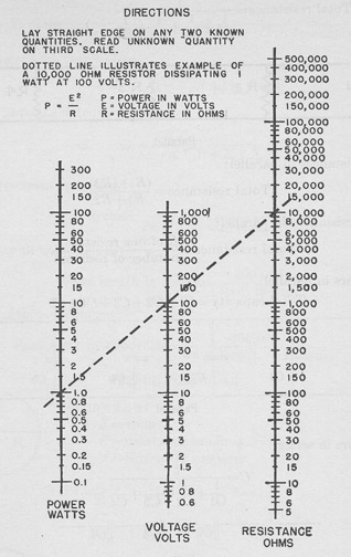
4.46 RESISTOR WATTAGE CHART
4.47 Formulae
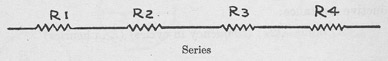
Resistances in series:
Total resistance = R1 + R2 + R3 + R4
176
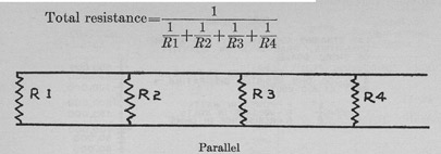
Resistances in parallel:
Two resistances in parallel:
Total resistance= (R1)(R2) / (R1 + R2)
Equal resistances in parallel:
Total resistance = (R of one resistor) / (number of resistors)
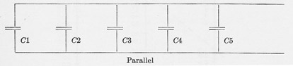
Capacitors in parallel:
Total capacity = C1 + C2 + C3 + C4 + C5
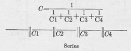
Capacitors in series:
Two Capacitors in series:
C = (C1)(C2) / (C1+C2)
Inductive reactance:
XL ohms= (2π) (frequency in cycles) (L in henries)
177
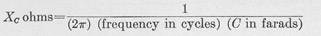
Capacity reactance:
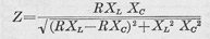
Series impedance (equivalent):
Parallel impedance (equivalent):
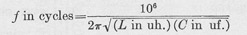
Circuit resonant frequency:
Frequency to wave length:
Wave length in meters = 300,000 / freq. in kcs.
Wave length to frequency:
Frequency in kilocycles = 300 / wave length in meters
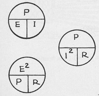
USEFUL FORMULAE
Ohm's Law: E = volts R = resistance in ohms I = current in amperes
I = E/RR = E/IE = IR
Power:
P = power in watts
P = EI
E = P/I
I = P/E
P = I2R
I = sqrt(P/R)
R = P/I2
E = sqrt(PR)
P = E2/R
R = E2/P
178
179
180
4.6 Vacuum Tube Data
TUBE DESIGNATIONS
Originally, vacuum tubes were numbered as they were developed, and many numbered tubes are still in use, such as the 45, 76, 80, etc. Since such designations give no clue as to the type of tube or its characteristics, other methods have been adopted.
For receiving tubes, a fairly standard system is in effect. This system involves a number, one or two letters, a number, and sometimes added letters. The first number gives the filament or heater voltage to the nearest volt. The following letter gives the general class of the tube, with the letters at the beginning of the alphabet used for amplifiers and detectors, and those at the end of the alphabet for rectifiers. After the alphabet was exhausted, double letters came into use, on the same general system. The second number indicates the number of elements in the tube.
Thus a 2A3 is an amplifier with 2.5 volt filament, with three elements, a plate, grid, and filament. A 25Z5 is a rectifier with 25 volt heater and five elements.
The added letters indicate various other features. Thus the 6L6-G is a glass tube of type 6L6 with an octal base.
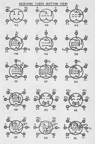
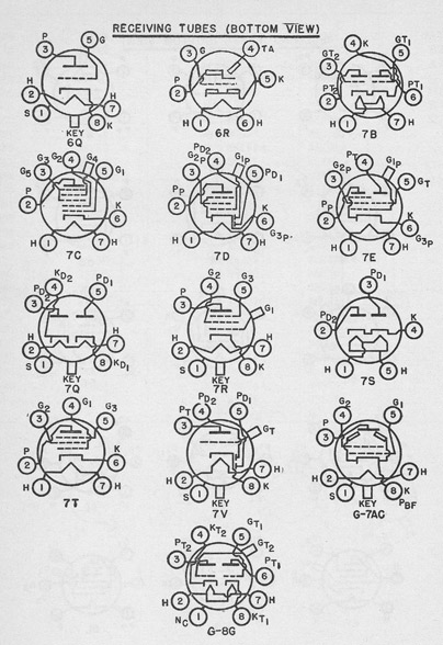
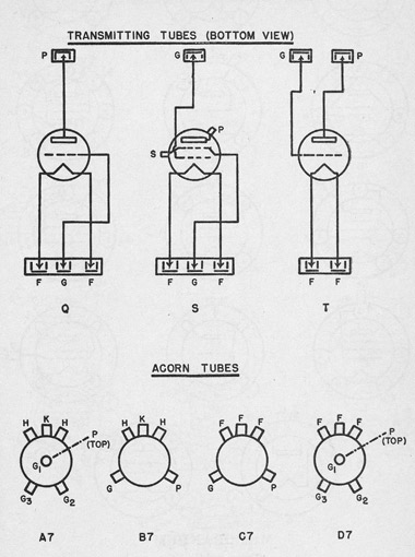
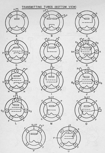
Older tubes have 4, 5, 6, or 7 base pins or prongs. Most modern tubes have octal bases, that is, eight prongs surrounding a central guide or key. Loktal tubes and new miniature tubes have special bases with the pins sealed into glass.
Transmitting and other power tubes are not as well standardized in designation as receiving tubes. Generally speaking, all transmitting tubes are numbered in the 800 to 900 range. Tubes in the 900 to 1,000 range may be cathode ray, television, or "acorn" types. Tubes in the 1,600 series are specially designed to eliminate microphonic noise.
The general systems described above are now used by almost everyone making or using vacuum tubes.
181
CROSS INDEX
Old and New Tube Type Numbers
New
Old
Base*
New
Old
Base*
01-A
38001
4D
41
38041
6B
1B4-P
38032A
4M
42
38042
6B
1c6
38236
6L
45
38045
4D
1E7-G
38717E
G-80
47
38047
5B
2A3
38213
4D
50
38050
4D
2A5
38215
6B
53
38053
7B
2B7
38227
7D
56
38056
5A
5Z3
38593
4C
57
38057
6F
6A6
38616
7B
58
38058
6F
6A7
38617
70
59
38059
7T
6B7
38627
7D
71-A
38071
4D
6C6
38636
6F
75
38075
6G
6D6
38646
6F
76
38076
5A
6E5
38655
6R
77
38077
6F
6F7
38667
7E
78
38078
6F
6F8-G
38768F
G-8G
80
38180
4C
6H6
38566H
7Q
81
38181
4B
6J5
38565J
6Q 82
38182
4C
6J5-G
38765J
*G-6Q
83
38183
4C
6K7
38567K
7R
84
38184
7S
6K8
38568K
8K
85
38085
6G
6R7
38567R
717
89
38089
6F
6Y6-G
38766Y
G-7AC
112-A
38012
4D
10
38110
4D
203-A
38103
M
19
38019
6C
204-A
38104
Q
22
38022
4K
206
38106
24-A
38024
5E
207
38107
25Z5
38255
6E
211
38211
M
27
38027
5A
214
38114
30
38030
4D
217-C
38117
31
38031
4D
218
38118
32
38032
4K
219
38119
33
38033
5K
801
38101
C
34
38034
4M
803
38803
L
35
38035
5E
807
38807
H
36
38036
5E
808
38808
E
37
38037
5A
814
38814
J
38
38038
5F
833
38833
T
39
38039
5F
836
38266A
A
40
38040
4D
837
38837
G
*Refers to tube base diagrams on following pages.
182
Old and New Tube Type Numbers-Continued
New
Old
Base*
New
cad
Base*
838
38138
M
954
38954
A7
842
38842
C
955
38955
B7
843
38143
D
956
38956
A7
845
38145
M
958
38958
C7
846
38146
959
38959
D7
849
38149
Q
1616
38267
B4
850
38150
O
1853
38853
8N
851
38151
Q
38015
38015
852
38152
E
38111A
38111A
857-B
38157B
38112
38112
858
38158
38116
38116
860
38160
U
38120
38120
861
38161
S
38142
38142
862
38162
38205
38205
864
38064
C
38217
38217
865
38165
I
38222
38222
866-A
38166A
A
38233
38233
868
38268
38250
38250
869-A
38169
38278
38278
870
38170
38282
38282
871
38171
A
38401
38401
872-A
38172A
P
38402
38402
874
38274
4S
38403
38403
876
38276
38412
38412
884
38884
6Q
38674
38674
886
38286
X
38674A
38674A
893
38192
38897
38897
183
184
185
186
MEMORANDUM
The following publications contain additional information of value:
Manual of Engineering Instructions. (New Title: Bureau of Ships Manual)
Chapters on Interior Communications, Motors and Generators, Radio, Sound and Radio Direction Finders:
Radio and Sound Bulletins, Bureau of Ships. Bureau of Ships (Engineering) Circular Letters.