In number and complexity of parts, most transmitters are simpler than receivers. At the same time, however, intelligent transmitter servicing requires as good a knowledge of the basic principles of operation of the circuits used as does receiver servicing. This is because a great many receiver servicing operations can be reduced to routines followed step by step, while it is not so easy to do the same thing for transmitters.
This section will attempt to outline the fundamental circuits used in transmitters and explain the practical operating characteristics of each one. Some of the details of the troubles peculiar to each type of circuit will be given. A knowledge of basic theory and common troubles, together with a study of the circuit diagram and instruction book on any particular transmitter, are usually adequate for servicing any equipment.
Any electrical device that uses high voltage is extremely dangerous. Every transmitter operates at voltages that will kill instantly if given an opportunity by a moment's thoughtlessness. Designers try to reduce the hazard by providing safety devices, but the only true safety device lies in the care and thoughtfulness of men working on transmitting equipment.
Study and remember the abridged safety precautions found below. Study the service manuals and letters on safety precautions. Study the safety features outlined in the instruction books. Follow the basic safety rule always:
STOP! LOOK!
THINK FIRST
DEATH IS PERMANENT
DANGER! HIGH VOLTAGE!
Learn resuscitation methods. See that your shipmates learn resuscitation methods, your life may depend on it.
In case of accident, make sure the power is off the circuit before attempting to assist an injured man.
Apply artificial resuscitation promptly.-Sixty seconds delay may mean the difference between life and death.
101
SAFETY PRECAUTIONS
STOP! LOOK! THINK!
NEVER TAKE CHANCES
Keep Cool and Take Your Time.
Do Not Hesitate To Shut Down Equipment
A Delay Is Preferable to a Serious Accident.
Before Working on a Circuit
BE SURE IT IS DEAD-TAG THE SWITCH
To Insure Against Accidental Closure.
ALL LEADS ARE ALIVE UNTIL PROVED DEAD
Do NOT WORK ALONE ON EQUIPMENT USING HIGH VOLTAGE
STAY IN FRONT OF THE PANEL
When Motor Generators or Rectifiers Are Energized
Make Internal Adjustments With the Power OFF.
USE ONE HAND FOR SWITCHING OR TUNING
NEVER DISABLE FUSES OR INTERLOCKS
Do Not Trust Interlocks or Door Switches.
Fuses and Interlocks Are Safety Devices. Replacement
Fuses Must Have the Correct Rating.
DEAD EQUIPMENT MAY RETAIN DANGEROUS CHARGES
Be Safe-Discharge Dead Equipment to Ground.
Short Circuit or Ground Condensers.
FIRE!
STOP! LOOK! THINK!
Quick Action Is Required Only in Opening the Circuit.
A CO2 Fire Extinguisher Directed at the Base of the
Flames Is Most Effective for Electrical Fires.
Pyrene or Carbon Tetrachloride Must Not Be Used in
Closed Spaces or on Live Circuits.
102
SAFETY PRECAUTIONS
STOP! LOOK! THINK!
Danger! Explosive Gases!
Do Not Use Alcohol, Paint, Varnish, or Gasoline
Anywhere Near Electrical Equipment From Which a
Spark Is Possible
Keep Flames and Sparks Away From Vicinity of
Storage Batteries.
LIVE PANELS ARE LETHAL!
Stowage of Foreign Articles in or Around Electrical
Equipment Is Forbidden.
Clean Panels and Boxes Only With a Nonmetallic Painter's
Duster.
Do NOT Go ALOFT
When Antennas Are Energized. Do Not Work on Any
Antenna When the Adjacent Ones Are Energized.
Intentionally Taking a Shock From ANY Voltage
IS FORBIDDEN!
Learn Location of Emergency and Regular Power
Switches.
In Case of Accident, Shut Off the Power
Before Touching the Victim.
Then Apply Resuscitation and Send for the Doctor.
S-A-F-E-T-Y A-L-W-A-Y-S!
T-A-K-E Y-O-U-R T-I-M-E!
CIRCUIT TERMS AND DEFINITIONS
Some of the terms and definitions applied to transmitter circuits are outlined below.
Tank Circuit.-The tuned circuits of capacity and inductance used in vacuum tube transmitter circuits are frequently called "tank" circuits, because from one viewpoint they act as tanks or reservoirs of RF energy.
103
By-pass Capacitors.-By-pass capacitors furnish a low impedance path around a circuit element for RF or AF current.
Blocking Capacitors.-Blocking capacitors are used to provide a high impedance path for DC or low-frequency AC, and so prevent the flow of such currents without appreciably affecting the flow of RF.
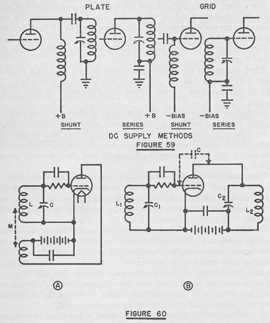
Series and Parallel Feed.-The DC grid and plate voltages required for tube operation may be fed through the coil of the tuned circuit, or may be fed through a choke in parallel with the tuned circuit. In the first case the voltage feed is called series feed, in the second, it is called parallel feed. The connections are shown in Figure 59.
Filament Center-Tap.-When filament type tubes are heated by AC, the grid and plate returns must be made to the electrical center, or center-tap, of the filament circuit in order to avoid hum.
Excitation.-In transmitters, the AC signal voltage applied to the grid of a tube is called the excitation, or the exciting or driving voltage. Exciting or driving power is the power required to develop the exciting voltage across the grid circuit. Oscillators supply their own excitation, but amplifiers must be driven by voltage from an oscillator or from another amplifier.
Power Input.-Unless otherwise specified, the term power input applies to the DC power consumed in the plate circuit. It is the product of the DC plate voltage and current.
Power Output.-It is important to distinguish between the tube power output and the circuit power output. The tube output does not take into account the tank and coupling circuit losses.
Antenna Feeding.-Distances along an antenna are usually expressed in terms of electrical wave length. Every half wave length there will be a point of high RF voltage. There will be a high current point half way between any two high voltage points, that is at the quarter-wave points. A voltage fed antenna is one which is excited at one of the high voltage points, that is at a point of high impedance. A current fed antenna is one that is fed at a point where the current is high and the -voltage low, or a point of low impedance. Transmitters often have loading networks built into the output circuit which may be switched in and out to change the effective electrical length of the antenna.
TRANSMITTER UNITS
Oscillator.-This is the radio frequency generating unit which supplies the excitation voltage to the amplifiers at the desired frequency.
Intermediate Amplifiers.-These amplifiers take the RF generated by the oscillator and increase the signal to sufficient strength to drive the power amplifier output stage. Intermediate amplifiers may be designed so that their output frequency is higher than the oscillator
104
frequency. When used for this purpose they are usually called frequency multipliers.
Buffer Amplifiers.-Oscillator circuits will be most stable as frequency generators when they are not required to deliver appreciable power, especially when the power demand fluctuates. Consequently, a buffer amplifier is frequently used as the first stage after the oscillator. This buffer needs only a small driving voltage from the oscillator and may transfer the signal voltage to the next amplifier without amplifying it. Such a circuit serves to isolate the oscillator from changing conditions in the later stages of the transmitter and hence the name buffer.
Power Amplifier.-This final amplifier is excited by the intermediate amplifiers and increases the signal power to the desired output value before delivering it to the antenna circuits.
Output Circuits.-The plate circuit load of the power amplifier must usually be a fairly high impedance if the amplifier is to operate effectively. An antenna is usually a rather low impedance circuit. The transmitter output circuits must be designed to couple, or match, these two different impedances so that the maximum energy practicable will be usefully fed into the antenna. Various arrangements of inductance and capacity are used in the coupling networks.
MISCELLANEOUS
Harmonics or Harmonic Series.-Although a crystal or a resonant circuit will have only one fundamental resonant frequency, it will respond fairly readily to frequencies that are integral multiples of the fundamental frequency. These frequencies are said to be in harmonic relationship to the fundamental frequency and hence are referred to as harmonics. A fundamental frequency and its harmonics are referred to as a harmonic series. In practice, the fundamental is the first harmonic, the frequency twice the fundamental is the second harmonic, etc. A typical series would be 4135 kcs fundamental, 8270 kcs second harmonic, 12,405 kcs third harmonic, and so on.
3.11 Oscillators
The oscillator is the radio frequency current generating unit of the transmitter. An oscillator takes the direct current power supplied to it and converts a part of this energy into radio frequency current. The operation of an oscillator is governed by the characteristics of the external circuits as well as by the tube. Basically, it is the ability of a tube to amplify that enables it to generate alternating current power.
105
Figure 60 shows two common oscillator circuits. In both A and B of the figure, a part of the amplified output of the tube is fed back into the input circuit.
In A. the energy is fed back through the mutual inductive coupling M. In B the energy is fed back through the tube plate-grid capacity C.
In A the frequency of oscillation will be very nearly the frequency to which the circuit L1-C1 is tuned, while in B the frequency will be determined by the joint action of L1-C1 and L2-C2.
The voltage that is fed back and applied to the grid of the oscillator must be 180 degrees out of phase with the voltage across the impedance in the plate circuit. Sufficient power must be fed back to make up for any power losses in the grid circuit due to its natural resistance.
The manner in which a tube oscillates will be described with the aid of Figure 60-A.
When the grid is connected to the cathode by a grid leak resistor there will be zero bias on the tube when it is not oscillating. A tube in this condition is very unstable and sensitive to any circuit change.
As the power is turned on, the first surge of electrons from cathode to plate will cause a change in plate current which will cause a voltage to be induced across the grid circuit. The gird will then change the plate current, causing another change in the grid voltage. Very shortly this action will be repeating itself rapidly and the tube will be oscillating.
These oscillations will continue to increase in magnitude until a limit is reached. This limit will be determined by the losses of the tank circuit as influenced by the load coupled to it or by the limit set by the amount of electron emission that the tube filament or heater will produce.
When the tube is oscillating, the plate current will be less than when it is not oscillating. This is because the coupling is mutual, that is, with power being supplied to the grid circuit, the effect of the coupling is to increase the impedance of the plate circuit. This increase in impedance will reduce the plate current flowing.
Oscillators can be divided into two groups, the self-excited, as described above, and the crystal-controlled, in which the oscillation frequency is principally determined by a quartz crystal.
The self-excited oscillator can be connected in a number of different circuit arrangements but most of them have relatively poor frequency stability. The self-excited oscillator has the advantage of being very flexible, that is, it may be adjusted to produce any frequency within its operating range.
The crystal-controlled oscillator has excellent frequency stability, particularly when it uses specially cut crystals or when the crystal is
106
mounted in a temperature-controlled oven. The disadvantage of the crystal control is that it is necessary to have a separate crystal for each frequency or harmonic series of frequencies.
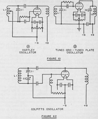
In the Hartley oscillator the tuned circuit is connected between the grid and plate of the tube as shown in Figure 61-A. The frequency is determined chiefly by the constants of the tank circuit L1 and C1. The interelectrode tube capacities affect the frequency somewhat.
The filament circuit of the tube is connected, or tapped, to the coil LL The amount of feedback or grid excitation is changed by moving this tap. As the tap is moved toward the plate end, the excitation increases. With most tubes, from half to two-thirds of the turns of L1 will be included between the tap and the plate end for proper adjustment.
107
In the tuned plate-tuned grid oscillator shown in Figure 61-B, there are two tank circuits, one between grid and filament and one between plate and filament. These two circuits are not coupled inductively, the grid-plate capacity of the tube serving to provide the coupling.
The frequency of the oscillator is controlled mainly by the plate tank constants L2-C2 although the grid circuit constants do effect the frequency. The main function of the grid tank is to control the feedback or excitation. For normal' operation, it is tuned to a slightly lower frequency than the plate tank circuit.
In the Colpitts oscillator the filament is connected to the junction of two capacitors that are connected in series across the coil. This circuit is shown in Figure 62.
510493°-43-8
108
Excitation is controlled by varying the two capacitors in such a manner that the capacity of the two in series is constant, while the ratio, or division, of capacity between the two varies. Thus the grid and plate circuits divide the total voltage across the capacitor combination.
The frequency of oscillation is controlled by L1 and the total capacity of C1 and C2 in series.
The electron-coupled (Dow) oscillator, developed from the fundamental circuits already discussed, is made possible by, the screen grid tube. Its advantage lies in the fact that by proper design it can be made nearly as stable as a crystal-controlled oscillator and still be very flexible.
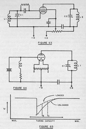
Figure 63 shows a simple electron-coupled oscillator. The control grid, cathode, and screen grid combine to form a triode oscillator, which in this case is connected as a Hartley oscillator. A Colpitts circuit could be used.
The triode oscillator behaves like a Hartley oscillator, that is, the frequency is controlled by L1-C1 and the feedback controlled by moving the tap on the coil.
In addition to this action, however, the electron stream flows in normal fashion to the plate of the tube, the flow varying as the triode elements continue to act as an oscillator. If the plate is well screened by the screen grid, the transfer of energy to the plate is almost entirely through this electron stream and not through capacity effect.
The plate circuit is tuned by L2-C2 and may be tuned to the second harmonic instead of the fundamental. If tuned to any higher harmonic, it will be found that the output power is very low.
The circuit arrangement is such that the plate and screen grid circuits tend to stabilize the oscillator. For example, if the proper screen and plate voltages have been selected, a change in the voltage supplied will not affect the frequency of oscillation as it does in the simpler oscillator circuits. Instead, it will be found that the tendency to change frequency, due to voltage change on the screen, will be counteracted by a tendency of the plate to change frequency in the opposite direction.
There are many circuit variations in oscillators using the electron-coupled principle, as the circuit has been used for many applications.
When an oscillator must be held very accurately to one definite frequency, a crystal-controlled oscillator is used. The simplest circuit is the triode oscillator shown in Figure 64.
When the plate tank circuit L1-C1 is tuned to a frequency slightly higher than the natural frequency of the crystal, there is feedback through the gridplate capacity of the tube, which excites the grid circuit, and the crystal will oscillate at approximately its natural frequency.
109
The DC plate current of the tube will be steady when the crystal is not oscillating, but will decrease or dip when the tank circuit L1-C1 is tuned to resonance with the crystal.
The peculiar relation between the tuning of C1 and the plate current is of practical interest. This is shown in Figure 65. Notice also that this characteristic changes when the output circuit is loaded, that is, when the oscillator is coupled to an amplifier.
As the capacity is changed from minimum to maximum, there is a gradual decrease in plate current as oscillations commence. This decrease continues to the point marked A in Figure 65. If the
110
capacity is increased slightly beyond the value corresponding to A, there will be a sharp rise in plate current and the circuit will stop oscillating.
This indicates that if the circuit is tuned to a point corresponding to A of the figure, it is very apt to drop out of oscillation due to a minor variation of plate voltage.
It is better to operate the circuit tuned so that it operates in the region marked B-C in Figure 65. The oscillator will be more stable and less apt to drop out of oscillation. This is particularly true when the oscillator is loaded.
Notice also that the effect of the load is to decrease the dip in plate current. The greater the load, the more power is taken from the oscillator, and if the load is too high the crystal will not oscillate.
High current will damage a crystal. Consequently, it should not be operated unloaded for extended periods or with too high plate voltages.
Additional notes on the operation of crystals will be found in Section IV.
INTERSTAGE COUPLING SYSTEMS
Interstage coupling systems are used to transfer the power developed by a driving tube to the grid circuit of the following amplifier with as little loss as possible.
General coupling methods may be divided into three classes: direct coupling, transformer coupling, and link coupling.
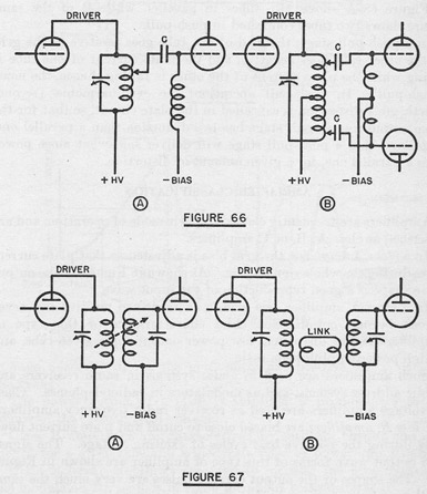
The two circuits of Figure 66 use direct capacitive coupling, the most widely used variety of this type. The coupling, and hence 'the excitation, is varied by moving the tap or taps on the coil. In the push-pull stage of B, the two taps should be equidistant from the electrical center of the coil.
Figure 67-A illustrates variable transformer coupling. The excitation and coupling are varied by adjusting the coils so as to change their mutual inductance. The tuned circuits must be readjusted to resonance when the coupling is varied.
Link coupling is shown in Figure 67-B. As far as the coils are concerned, this is a variety of transformer coupling. Adjustment may be made at either end of the link by moving the link turns with respect to the tuned-circuit coils. If the line between the link coils has any great length, the system becomes a transmission line coupling method.
All coupling systems come under the broad heading of impedance matching devices. Impedance matching means, generally, that the load impedance presented to the source of power is transformed to suit the particular requirements of the case. The particular requirement in this case is the securing of the best possible transfer of
111
power to get optimum amplifier excitation. As discussed above, various coupling methods are used.
Full discussions of impedance matching will be found in standard radio engineering textbooks.
3.12 Amplifiers
General.-Oscillators are poor power generating devices and have limitations when used as such. Consequently, amplifiers are used with oscillators so that the oscillator can be operated to give a low power output and good stability. A heavily loaded oscillator is usually unstable and suffers from frequency shift.
The number of amplifier stages that are used after an oscillator will depend on the power output desired. Triodes, tetrodes, or pentodes may be used.
112
Triodes usually will require neutralization when used as straight amplifiers. When used as doublers, neutralization is not usually necessary since the plate circuit is tuned to twice the frequency of the grid circuit.
Screen-grid tubes do not need to be neutralized but there should be no coupling between the grid and plate circuits outside of the tubes, if unwanted oscillations are to be prevented. This means that the circuit leads must be carefully run and that the grid and plate circuits must be well shielded.
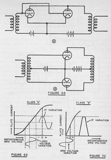
Amplifiers may operate with one tube per stage, or with tubes connected in push-pull or in parallel.
When connected in parallel, all of the corresponding elements in the tubes are connected together. The power output will then be in proportion to the number of tubes used, while the exciting voltage required will be the same as for one tube.
Figure 68-A shows two tubes in parallel, while B of the same figure shows two tubes connected in push-pull.
In a push-pull stage, the grid of one tube goes positive as the grid of the other tube goes negative, and the plate current of one tube is rising while the plate current of the other is falling; hence, the name "push-pull". In push-pull operation, the even-harmonic (second, fourth, etc.) distortion is cancelled in the plate circuit, so that for the same output a push-pull stage has less distortion than a parallel one. It follows that a push-pull stage will deliver somewhat more power than a parallel one, for a given amount of distortion.
AMPLIFIER CLASSIFICATION
Amplifiers are frequently classed by their mode of operation, and are described as class A, B, or C amplifiers.
In a class A amplifier, the grid bias is adjusted so that plate current flows during the whole signal cycle. As shown in Figure 69, the output wave shape is a good reproduction of the input wave.
In a class A amplifier, the grid is never driven positive and never driven beyond cutoff. The chief characteristics of this type of amplifier are low distortion, low power output for a given tube, and a high power amplification ratio.
Such amplifiers are used in audio systems in radio receivers and public address systems, and as modulators in radiotelephones. Class A. voltage amplifiers are used as receiver radio frequency amplifiers.
Class B. amplifiers are biased close to cutoff and plate current flows only during the positive half cycles of exciting voltage. The signal and output wave forms of this type of amplifier are shown in Figure 70. The shapes of the output current pulses are very much the same as those of the positive half cycles of exciting voltage. The signal
113
voltage normally drives the grid somewhat positive for a part of the cycle.
The power output of a class B amplifier is proportional to the square of the exciting grid voltage.
Class B amplifiers are characterized by medium output and efficiency for a given tube and a moderate ratio of power amplification.
Class B linear amplifiers are used to increase the power level of the modulated RF signals in radio telephone transmitters.
114
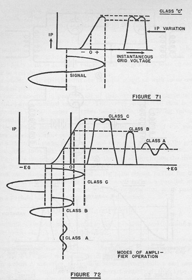
The class C amplifier is normally operated with a grid bias of about twice the value required for plate current cutoff without excitation. As a result, plate current flows only during a part of the excitation cycle, as shown in Figure 71.
The exciting signal drives the grid positive on cycle crests, and drives the plate current to the saturation point. Since the grid robs the plate of electrons when the grid is very positive, there is a dip in the plate current pulse near maximum value.
115
A class C amplifier has high plate efficiency, high power output, and a relatively low power amplification ratio. The output power is proportional to the square of the plate voltage. Class C amplifiers are widely used in radiotelegraph transmitters.
In Figure 72, the operation of class A, B, and C amplifiers is shown on one diagram to illustrate the difference between the modes of operation.
INTERMEDIATE AMPLIFIERS
Amplifiers between the oscillator and the output stage are frequently named for their functions, such as buffers, doublers, and multipliers. Such amplifiers can be described generally as intermediate amplifiers.
Buffer amplifiers serve to isolate the oscillator from changes of load reflected back from succeeding stages. When used in this fashion, such stages are straight amplifiers, and do not change the frequency of the signal in amplifying it.
Frequency doublers have their plate circuits tuned to the second harmonic of the input signal. The output of such a stage will be twice the frequency of the input signal. Push-pull amplifiers cannot be used as doublers because the circuit arrangement automatically cancels out the second and other even harmonics.
Triplers or other types or multipliers have their plate circuits tuned to the third or higher harmonic.
Frequency multiplying stages do not have as high an output as straight amplifiers unless the tube excitation, or driving power, is high because the power in the harmonics is less than the power in the fundamental. A doubler may require as much as two or three times the driving power needed to operate it as a straight amplifier.
POWER AMPLIFIERS
The final stage in any transmitter is frequently called the power amplifier. It operates at the highest power level of any stage, and determines the available power that can be delivered to the antenna circuit.
The power amplifier may be any one of several types. It may be a single tube stage or a push-pull or parallel arrangement.
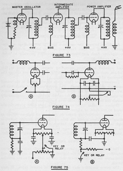
Figure 73 shows the simplified diagram of typical stages of a transmitter in which a crystal oscillator feeds one intermediate amplifier, which in turn drives a power amplifier.
3.13 Keying Circuits
A telegraph transmitter must have an arrangement for breaking up the outgoing signal into dots and dashes. The keying circuit must
116
be designed so that the outgoing signals are intelligible and so that the keying action does not change the transmitter frequency.
The three general types of keying are plate voltage control, excitation control, and tone keying.
In plate keying systems, such as that shown in Figure 74-A, the key may be connected in series with the primary of the plate transformer or in the negative plate lead. Such methods of keying are not very satisfactory.
117
There are two general types of excitation control. In one type the oscillator or intermediate amplifier circuit is actually interrupted. In the other type, one of the amplifiers has a controllable grid bias. When the key is open, such a tube is biased well beyond cutoff. When the key is closed, the bias is reduced and the tube operates. This is sometimes called blocked grid keying. Many modern transmitters are keyed this way. Figure 75 shows two simple grid keying methods.
A combination of grid and plate keying is shown in Figure 74-B. This arrangement, which is not very satisfactory, is sometimes called center-tap keying.
Sometimes it is desirable to have a radiotelephonic transmitter arranged so that it can be used for telegraphic transmissions. In this case, tone keying is used. A separate oscillator, which can be keyed, generates an audio frequency. This AF is fed into the modulating equipment of the set, and the transmitter then sends out dots and dashes in the form of a modulated wave. Such an arrangement is fairly common in low power UHF telephones.
118
3.14 Modulation
Modulation is the process by which radio frequency waves are made to carry intelligence. This intelligence is ordinarily speech or music, though, strictly speaking, a continuous-wave telegraph transmission is also modulated. This discussion will be limited to speech modulation.
To have modulated transmission, the equipment must include:
(a) The generator of a radio frequency wave, commonly called a carrier wave.
(b) A means for converting sound energy into electrical energy, ordinarily called a microphone.
(c) A device for combining the speech waves and the carrier wave, usually called a modulator.
(d) Any further amplifiers required to raise the modulated wave to the desired power.
Any oscillator and amplifier arrangement may be used to generate the carrier wave.
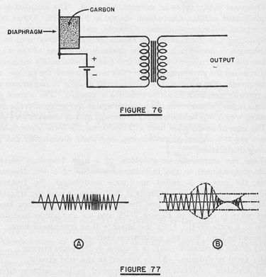
There are many types of microphones used. The simplest is the single-button carbon microphone shown in Figure 76. Other types are crystal, velocity, condenser, dynamic, and line microphones.
Speaking into the microphone causes the sound waves to move the diaphragm in accordance with the pressure variations of the waves. When the diaphragm moves back and forth it alternately compresses and releases the carbon granules. The resistance of the carbon, and consequently, the magnitude of the current flowing in the primary of the transformer, changes as the pressure is changed. The current variations in the primary will induce a voltage in the secondary, the wave form of which will be essentially the same as that of the sound wave.
The type of modulation used will determine the form of modulator. There are two classes of modulation, amplitude modulation and frequency modulation.
When the amplitude, or envelope, of a high frequency wave is made proportional to the instantaneous value of a low frequency wave, the process is called amplitude modulation. In frequency modulation, the carrier amplitude is held constant, and the frequency of the wave is varied at a low frequency rate. A frequency modulated wave is shown in Figure 77-A and an amplitude modulated wave in Figure 77-B. Only the latter will be considered here.
There are four principal modulation methods:
(a) Plate modulation-AF is applied to the plate circuit.
(b) Grid modulation-AF is applied to the grid circuit.
(c) Cathode modulation-AF is applied in the cathode circuit, affecting both plate and grid circuits.
(d) Suppressor grid modulation-AF is applied to the suppressor grid.
119
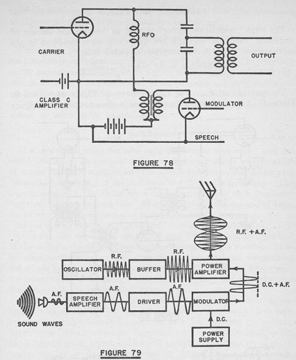
A simple form of plate modulator is shown in Figure 78.
In this type of modulator, the plate voltage is varied at speech frequencies. When properly adjusted such a circuit will have an output voltage almost exactly proportional to the plate voltage, and will reproduce the desired modulation without appreciable distortion.
The operation of a complete transmitting system which radiates modulated waves is portrayed in Figure 79.
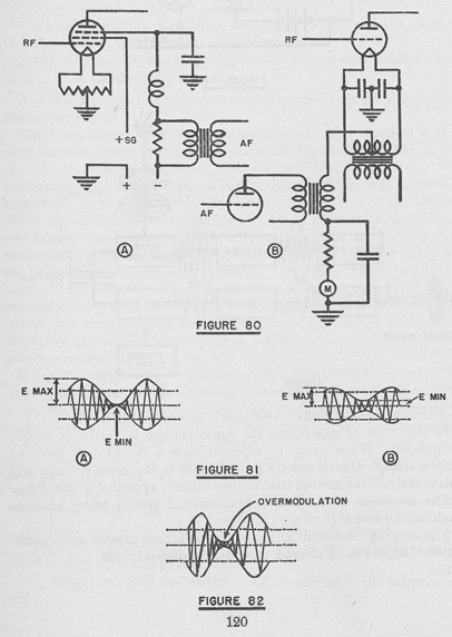
Figure 80-A illustrates a simple circuit for suppressor grid modulation. Figure 80-B shows a cathode modulated triode.
120
DEGREE OF MODULATION
The term "modulation factor" is used to describe the amount of amplitude variation that the low frequency wave produces in the carrier wave. This factor may be calculated from:
Modulation factor = m = (Emax - Emin)/Emax
The meaning of Emax and Emin is shown in Figure 81. Thus in Figure 81-A the modulation factor would be close to 1, while in Figure
121
81-B the modulation factor would be about 0.5. It is also convenient to express the degree of modulation as a percentage:
Percentage modulation= (m) (100)
Ordinarily, the modulation of a particular transmitter is given as the percentage modulation. Thus Figure 81-A could also be described as 100 percent modulation, while Figure 81-B might be called 50 percent modulation. If a moderator is not properly adjusted, over modulation can occur. Figure 82 pictures an over modulated wave.
Over modulation causes distortion and may make transmission of speech or music quite unintelligible.
SIDEBANDS
If a modulated wave contains only the carrier frequency and one audio frequency, an analysis will show that the voltage wave consists of the sum of three components: the carrier frequency, the carrier plus the audio frequency, and the carrier minus the audio frequency. The transmission of a modulated wave thus involves three high frequency currents: the carrier, and two "sideband" frequencies separated from the carrier by an interval equal to the modulating frequency.
If the carrier is 1000 kilocycles and it is being modulated by a 1000 cycle wave, the signal will consist of 1001 kcs, 1000 kcs, and 999 kcs. If the modulating wave is speech or music containing a number of frequencies, each frequency will give rise to two sideband frequencies, the whole group centering on the carrier. The sideband frequencies are independent of the amount of modulation; they will depend on the frequencies in the modulating wave.
A modulated signal will occupy a band of frequencies equal to the carrier plus and minus the highest modulating frequency. For telegraph signals the sidebands need only be a few hundred cycles wide. Intelligible speech requires frequencies up to at least 2500 cycles. High fidelity music transmissions will include frequencies up to 10,000 cycles, the whole wave then occupying 20,000 cycles of the radio frequency spectrum.
3.21 Motors and Generators
In dealing with electrical machinery, as with all electrical equipment, the instructions and safety precautions must be carried out at all times. A few of the more important machinery safety precautions are outlined below.
(1) The interior and exterior of machines, panels, and control boxes must be kept free from dust, dirt, water, salt, lint, and oil at all times.
122
(a) A small bellows or compressed, dry air may be used in cleaning interior parts. When brushes are used they must be entirely nonmetallic.
(b) Gasoline and other inflammable liquids must never be used near any piece of equipment that can produce a spark which may ignite the liquids or vapors.
(c) Emery cloth or paper shall never be used on electrical equipment.
(2) Protective devices for machinery, such as circuit breakers, fuses, and interlocks, must be kept in working order and operating with their designed settings or ratings at all times.
(3) Fuse box, junction box, and panel covers must be kept on and properly secured at all times. Lever type boxes shall be kept closed. Box gaskets will be kept in good condition and free from paint.
(4) When machines run at excessive temperatures or when there is sparking, the machines must be shut down and the defects causing improper operation corrected. Failure to do so will damage or destroy the machines.
(a) Great care must be taken in working on the brush rigging of running machines or the commutator may be seriously damaged.
(5) After an overhaul, electrical machinery shall not be started until a careful inspection has been made for loose bolts, tools, broken insulation, metallic dust or chips, improper clearances, and loose connections. The lubrication must be checked. Machine speed, output, current, and other readings should be taken, compared with the normal readings in the instruction book, and recorded.
(6) Except in serious emergencies, machines shall not be operated at more than the designed load. The upper limit of 25 percent overload shall never be exceeded.
ARMATURE TROUBLES
The three types of troubles encountered in armatures are mechanical defects, short circuits, and open circuits.
Mechanical defects.
(a) Journals worn, scored, or out of round.
(b) Commutators scored, pitted, worn out of round, or worn unevenly ; exposed mica segments.
(c) Windings loosened up or thrown out, binding wires broken or stretched.
Careful inspections and measurements will reveal any of these defects. Since machine shop or electrical shop facilities are required, repairs to remedy these defects will not be discussed here.
Short circuits.
(a) In individual coils (most common fault).
(b) Between adjacent coils.
123
(c) To frame or core.
(d) Between armature sections.
(e) Partial shorts of any of above types.
Short circuits usually make their presence known by violent armature heating, accompanied by the smell of overheated or burning insulation. There is usually a flickering of any lights in the circuit and sparking at the commutator.
When such symptoms are observed, the machine should be stopped at once to avoid complete destruction of the armature. In addition to the short circuits mentioned above, occasionally metallic dust or chips lodged in the commutator insulating segments will cause similar symptoms.
After the machine has been stopped, the faulty coil can frequently be located by its excessive temperature or by the baked, changed color appearance of the insulation or varnish.
Open circuits.-Partial or complete breaks in an armature circuit are ordinarily not accompanied by excessive heating. There will be heavy sparking at the commutator, the circuit at fault being indicated by a blue snappy spark just as the affected commutator bar moves under a brush. If the circuits are badly broken up there may be a ring of fire around the commutator due to the spark holding between bars.
When no break can be found, passing a fairly heavy current through the armature will either definitely open the break or indicate its location by local heating.
In an emergency when no spare armature is available, it is sometimes feasible to disconnect the broken coil from its commutator segments and insulate the loose ends. The disconnected segments should then be bridged with a well soldered strip of copper that will carry the armature current. Such a repaired armature should be replaced at the earliest opportunity.
TESTS FOR OPEN AND SHORT CIRCUITS
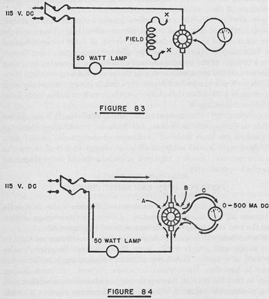
Bar-to-bar tests, lap wound armatures.-Disconnect the field coils and remove all but one set of brushes. Connect a low voltage source across the two remaining brushes as indicated in Figure 83.
The armature will normally have a very low resistance so that to test it safely and satisfactorily some thought must be given to the lamp used as a load. This lamp must be small enough to limit the current to less than the normal armature current. It must be big enough so that the current flowing through each armature section will give a measurable value of voltage drop. In many cases a 50-watt lamp, as shown, is satisfactory but the possibility that another size will be better must not be overlooked.
51049a°-43-9
124
After the circuit has been set up, take a low range voltmeter and read the voltage from bar-to-bar around the commutator, rotating the armature after each reading so that the bars will come under the brushes one by one.
For: Normal coils.-All voltage readings will be the same.
Open coils.-Voltage readings will be higher than normal.
Shorted coils.-Voltage readings will be lower than normal.
More than one coil open.-No readings when one, or more opens are on each side of the brushes.
The voltage drops to be measured are very small, so that the method outlined above is not too satisfactory. When a milliammeter is available, it is often better to take current measurements to check an armature. The general arrangement for this test is shown in Figure 84.
125
The lamp size must be selected to avoid possibility of overloading and damaging the meter. For example:
Line voltage =115 v DC
Meter maximum = 500 ma = .5 a
P= EI = (.5) (115) = 57.5 watts
A 50-watt lamp will be selected as the next lower size to check:
I = P/E = 50/115 = .460 a = 460 ma
The flow of current is indicated on Figure 84. If the armature is normal, the current will divide evenly between A and B. When the meter is connected, the current will divide three ways, part C flowing through the meter. If the bars being measured are shorted, there will be no current indicated by the meter. If the bar-to-bar circuit is normal, there will be a small current through the meter. If there is an open on the meter side of the circuit, the meter will read higher than for a normal coil. If there are opens on both sides of the armature, there will be no current and the lamp will not light until the meter is connected. The meter will then indicate the full circuit current.
An ohmmeter can be used to make bar-to-bar resistance measurements, with no voltage applied to the armature. However- the coil resistances are ordinarily so low that unless an exceptionally good, low range ohmmeter is available it will be hard to determine a partial short or shorted coil. A fully open coil will be indicated.
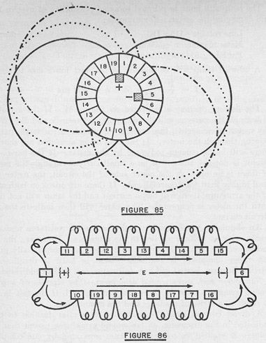
Bar-to-bar test, wave wound armatures.-The circuits of a wave wound armature must be thoroughly understood, if the test is not to result in a series of readings that are meaningless.
A direct current source is connected in similar fashion to that indicated in the discussion on lap wound armatures, except that the voltage is applied to commutator bars separated by one complete pole spacing, as indicated in Figure 85.
The circuit existing between the points of connection is drawn out in Figure 86. In the example given in this figure the direct current is applied to bars 1 and 6. The resistance from bar 1 to bar 6 will be about the same by either path. If the voltage drop across each coil could be measured it would be the same for all normal coils. However, the voltage drop measured from bar-to-bar will not be the same in all cases.
The table of Figure 87 indicates the readings to be expected in a characteristic armature. The values are given in millivolts. The bar numbers refer to the sketch in Figure 86.
Measuring between bars 1 to 6, a normal armature will show identical readings for each test. Starting with bar 6 to bar 7, the values
126
will be the same but with reversed sign. From bar 10 to bar 11, there will be no drop indicated because the voltages oppose each other. Likewise, there will be no reading between bars 15 and 16.
The second column of the table of Figure 87 summarizes the readings for a normal armature. It can be seen that there are two values of zero and that the remaining readings will be some constant numerical value, half being positive and half negative. If the armature has an odd number of coils there will be an extra positive or negative reading, the sign depending on the direction of current flow.
If a coil is shorted, there will be two zero readings and two abnormal readings of about half the normal voltage, as shown in the third column of Figure 87.
127
If two bars are shorted, there will be an extra zero reading and two half-value readings as indicated in column 4 of Figure 87.
If there is a coil open in a wave wound armature, there will be two readings of one-half value, a series of zero readings depending on the number of coils in the armature, and two high readings marked infinity in column 5 of Figure 87. These are marked infinity because the voltmeter serves as the whole conductor for the current in half of the winding and there is a possibility of meter damage if care is not taken.
If two coil leads are accidentally reversed there will be sparking at the commutator and the affected coils will overheat. There will be extra zero readings obtained in this case, as shown in column 6 of Figure 87. These readings occur because some of the coils are effectively short circuited upon themselves.
Except for very experienced men, the safest procedure to use in testing a wave wound armature is to draw a simplified circuit for the armature, similar to that of Figure 86. A table similar to Figure 87 should also be made up to use in recording and interpreting the bar-to-bar readings.
Bar-to-bar
Normal
Shorted coil
Shorted bars
Open coil
Reversed leads
1-2
10
10
10
0
10
2-3
10
10
10
0
10
3-4
10
5
10
0
10
4-5
10
10
10
oc
10
5-6
10
10
10
0
10
6-7
-10
-10
-10
-10
0
7-8
-10
-10
-10
-10
0
8-9
-10
-10
0
-10
-10
9-10
-10
-10
-10
-10
-10
10-11
0
0
0
-5
0
11-12
10
10
10
0
10
12-13
10
5
10
0
10
13-14
10
10
10
0
10
14-15
10
10
10
oc
10
15-16
0
0
0
-5
0
16-17
-10
-10
-10
-10
0
17-18
-10
-10
-5
-10
-10
18-19
-10
-10
-5
-10
-10
19-1
-10
-10
-10
-10
-10
FIGURE 87.
128
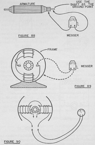
GROUNDED ARMATURE
An armature can be checked for grounds by the method illustrated in Figure 88.
A megger is used to read the resistance from the armature coils (commutator bars) to the shaft as ground. A normal armature should show a megohm or more resistance to ground on this test.
FIELD COIL TROUBLES
A grounded field coil may be detected by taking megger readings of the resistance to ground, connecting one lead to the frame and one to a lead of the field coil under test. Figure 89 illustrates this measurement. The brushes must be removed or lifted clear of the commutator for this test.
An open field coil may be detected by connecting an ohmmeter across the field input as shown in Figure 90. If the whole field is found to be open, test each individual field coil for continuity.
A shorted field coil is usually more difficult to locate than an open coil. The slight heating of a shorted coil is a fair indication. A low-range ohmmeter can be used to read the resistance of each field coil. The shorted coil will be indicated by the lowest reading.
A partially opened field coil can be detected by the method used for shorted coils, except that the defective coil will show an increased reading of resistance.
DEFECTIVE INSULATION
It will sometimes happen that a machine will show very poor insulation resistance. In such a case the armature or field coils should be dried out by being baked in an oven. When no drying oven is available, it is sometimes feasible to dry an armature or coil by passing DC through it to heat it slightly. Care must be taken to keep the current low to avoid overheating and damage to insulation.
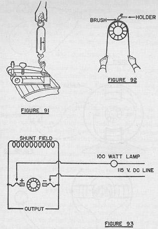
BRUSHES
The brushes are an important link in the electrical circuit since they must form the connection to the armature by way of the commutator. If the brushes fit poorly or the brush pressure is too low, the contact resistance may be very high. If the brush pressure is too high, particularly when the brushes do not fit, the commutator may be damaged by the brushes.
129
The actual brush pressure may be measured by using a spring balance as shown in Figure 91.
It is not practicable to give a fixed value of brush pressure for all cases, since it will vary with the equipment. Where the instruction book does not specify brush pressure, the brush spring tension should be adjusted so that:
Brush pressure in pounds= (1.5) (brush area in sq. in.)
When the brush pressure is too high, there will be sparking, excessive commutator wear, grooving, brush wear, and brush crumbling. When the brush pressure is too low there will be sparking, unsteady voltages, selective commutation, and unbalance in the armature circuits.
130
When renewing brushes, the commutator should be clean and free from grooves. If grooves have been cut, it should be turned down before new brushes are fitted. The new brushes are fitted into the holders and then lifted sufficiently to allow a sheet of coarse sandpaper to be slipped under the brush with the sanded side towards it. Figure 92 shows this arrangement.
The sandpaper should then be drawn under the brush, taking care to pull it only in the direction of rotation of the commutator. The brush must be raised in its holder while the sandpaper is being returned to the starting point to avoid cutting the brushes in the wrong direction. The ends of the sandpaper must be kept as close to the commutator as possible to avoid rounding the brush edges.
After the brush has been shaped to fit the commutator approximately, fine sandpaper should be used to get the final smooth fit, using the same process as is described above. After the fitting of
131
all brushes is completed, the dust and sand must be cleaned off carefully and the brush pressure checked.
The normal commutator acquires a hard, smooth finish having a medium chocolate-brown color, and should not be cleaned when it appears normal. It should never be lubricated with anything.
If a coating of smut and black carbon deposit appears on the commutator, it may be removed with carbon tetrachloride and a rag. If the commutator is very dirty, especially when slightly pitted, it may be cleaned with the finest sandpaper. After cleaning, the commutator must be carefully wiped off.
LOSS OF RESIDUAL MAGNETISM
Sometimes, when a generator is started, it will fail to build up and deliver any output voltage. This failure is usually due to loss of residual magnetism in the magnetic field. It is caused by an accidental connection of the field with reversed polarity.
The magnetism may be restored by the method shown in Figure 93.
The brushes are lifted clear of the armature to prevent a short circuit through it. Direct current is then applied to the field terminals for a few seconds to energize the field and remagnetize the poles. Care must be taken to insure connecting the direct current with the correct polarity. If no DC line voltage is available, a storage battery may be used.
After the field has been energized, the external voltage is disconnected, the brushes reset, and the machine started.
OPERATING TEMPERATURES
A great deal of electrical machinery is designed to operate at relatively high temperatures, much equipment being perfectly safe at 176 degrees Fahrenheit or more.
The hand is a very poor thermometer and should not be relied on except as a general indicator. A metal temperature of 120 degrees Fahrenheit is very uncomfortable to the touch.
When a thermometer is mounted on the outside of a machine, a correction of 15 degrees Centigrade or 27 degrees Fahrenheit should be added to the reading to compensate for the inability to read the true temperature within the machine itself.
The equipment instructions or the name plate usually show either the maximum safe operating temperature or the temperature rise of the machine when operating normally with full load.
132
LUBRICATION
Most motor generator sets and other small pieces of electrical equipment need lubrication at from 3 to 12 months periods, depending on the use given the machine and the manufacturer's instructions.
Electrical machinery is very frequently over lubricated so that the overflowing oil or grease damages the insulation. The equipment must be kept clean, and examined frequently for proper lubrication.
The proper kind of lubricant specified by the instructions should always be used.
If dirt and abrasive material get into the bearings, they must be carefully cleaned out. If practicable, it is best to disassemble the bearing and wash off the dirty lubricant with kerosene or light oil, wiping carefully with clean rags before replacing the parts.
When renewing lubricant, it is desirable to flush out the bearings with oil or grease. When a drain plug is fitted, clean grease should be forced through until it appears at the outlet. The surplus should be removed and the plugs replaced.
In an emergency, cake oil or grease can be flushed out with warm (not hot) kerosene. This procedure is not as desirable as taking down the bearing and cleaning it.
A good general rule is to see that every bearing surface is lubricated with the right amount of the proper lubricant at all times.
HOT BEARINGS
When a bearing is overheated, it must be cooled before the machine is stopped, except in a grave emergency, or the bearing and journal will "freeze" together. Slowing down the machine, forcing in new lubricant, or pouring light oil over the bearing may help to cool it off. It is dangerous to pour water on overheated metal because cracking may result.
Fortunately, the increased use of ball bearings, especially those of the sealed type, has reduced the trouble experienced with the bearings of small electrical machines.
INDEX OF MOTOR AND GENERATOR TROUBLES
Faults
Cause
Detection
Remedy
1. Too high voltage
Too high speed
Voltage high, lamps burn too bright.
Slow down machine.
Magnetic field too strong
Add resistance in shunt field.
2. Too low voltage
Too low speed
Voltage low
Increase speed.
Magnetic field too weak
Voltage low
Decrease resistance in shunt field.
Brushes not properly set
Voltage low
Rock brushes for highest voltage with sparklers commutation.
133
Index of motor and generator troubles-Continued
Faults
Cause
Detection
Remedy
3. Excessive current
Generator-lamp or motor load high.
Current high. Brushes sparking.
Cut out lamps. Reduce load on motors, or cut out motors.
Motor-too much work being done.
Excessive sparking of brushes. High current.
Reduce load on motor.
Short or ground in external circuit.
Excessive sparking of brushes. Heating of armature.
Locate and remove shorts or grounds.
Short circuit in armature coil.
Short-circuited coil heats more than others.
Stop machine. Locate coil. If entirely burned out, must be renewed.
Grounds in armature Two grounds to the core amount to short circuit.
Heating of short-circuited coil more than others.
Locate grounds, reinsulate the coils.
Excessive friction in bearings or armature striking pole pieces. Any cause tending to slow the motor.
Sparking of brushes. Sound of armature striking while running. Motor bearings heat up.
File away pole pieces or re-center armature. Clean and oil journals or refit bearings.
4. Excessive sparking at brushes.
Excessive current
Ammeter reads too high.
Reduce load on motor.
Brushes improperly set
Remove brushes and examine rubbing surface. Measure the peripheral distance between brush sets.
Fit and set accurately, then shift the brushes backward or forward until sharking is reduced to a minimum.
Brushes making poor contact with commutator.
By sighting between brushes and commutator.
Sandpaper the brushes and adjust the spring tension until they rest evenly on commutator.
Rough or non-concentric commutator.
Lightly touch chalk to commutator while running. Eccentric commutator by the rise and fall of the brushes.
Smooth commutator with sandpaper. If eccentricity is due to uneven wear of bearings, renew or reline.
High or flat bars in commutator.
By jumping or vibration of the brushes.
Same as above, or turn down commutator in lathe. Undercut mica to a depth of 1/32 to 1/16 inches.
Broken circuit in armature or commutator.
Commutator flashes, and is cut and burnt near the break. Flashing continues when armature is slowly turned.
Locate coil by drop of potential method. If in commutator, bridge over the break. If in armature coil, it must be renewed.
Weak field magnetism caused by broken circuit in field winding or short circuit in same two or more grounds in windings, reversal of one or more field coils.
Generator fails to generate full EMF. If every weak, motor runs very slowly, taking a current many times full load current.
Short circuits or grounds are easily located and remedied if external to the windings. If internal fault, coil must be rewound or repaired. A reversed coil will lower the voltage.
Unequal magnetism
One brush sparks more than the others.
Reshape pole pieces.
134
Index of motor and generator troubles-Continued
Faults
Cause
Detection
Remedy
4. Excessive sparking at brushes.
Dirty commutator causing brushes to vibrate, particularly if of carbon.
Flashing around commutator.
Clean commutator.
Poor brushes, especially if made of high-resistance carbon.
By ragged appearance of brushes around edges and formation of hard spots.
Renew brushes. Try different grades of brushes.
Vibration of brush holders, causing vibration of brushes.
By humming, singing sound of brushes.
Reduce cause of vibration or give the brushes a little greater pressure on the commutator.
4-B. Excessive sparking interpole machines.
Interpole polarity reversed
Remove armature. With low field excitation examine field polarity with a compass.
In motor, progressing in direction of armature rotation, polarity should be N-n-S-s. In generator progressing in direction of armature rotation, polarity should be Ns-Sn.
Brushes not set so that coils undergoing commutation are under interpoles.
Trace out by following up coil ends.
Usual setting is in geometric neutral. Set for minimum sparking under average load.
Interpole air gap too long or too short.
See if all interpoles are equal.
Adjustable when poles are bolted to the frame. Weaken interpole strength by shunting the interpole windings.
5. Heating of armature.
Excessive current. See causes under that heading.
Same as under excessive current.
Same as under excessive current.
Eddy currents and hysteresis.
Core becomes hotter than armature coils after running for a short time.
Improve ventilation by special fans or air guides if possible, re-insulate laminations.
Conduction from other parts as from commutator or bearings, the heat being conveyed to armature.
Other parts connected to armature, as commutator, shaft, or bearings hotter than the armature.
Locate source of heat by thermometer or by the hand. Correct by cleaning and lubrication.
6. Heating of commutator.
According to the particular cause given under sparking.
Conduction from other parts.
Same
If from bearings, lubricate or refit them.
Excessive current
Same
Discover cause of excessive current and correct.
7. Heating of field coils.
Excessive current in field circuit due to short circuits or grounds.
Too hot to bear the hand. If exceedingly hot, by varnish or insulation odor.
Locate the particular coil in which fault lies and repair or rewind. Methods given later.
Eddy currents in pole pieces, heat being conducted to the coils.
The pole pieces are hotter than the coils after a short run.
Only remedied by better design, use laminated pole shoes.
8. Heating of bearings.
Lack of lubrication
By feeling with hand. Oil cups empty or feeding pipes clogged.
Fill oil cups; clean feeding pipes.
Dirty or gritty bearings.
By feeling with hand.
Remove cap and thoroughly clean.
135
Index of motor and generator troubles-Continued
Faults
Cause
Detection
Remedy
8. Heating of bearings
Bearings out of line
Unequal wear of bearings. Shaft will not turn freely by hand.
Bearings must be lined up or shells re-babbitted. if very serious, new bearings will have to be made.
Rough or cut shaft.
Shaft will show the roughness in the bearings.
Turn down shaft in lathe. Scrape the bearings.
Shaft bent
Unequal wear in bearings, and armature will wobble. Very hard to move by hand,.
Shaft can be straightened only by disconnecting from armature and re-forging.
Oil ring stuck.
Inspection.
Adjust rings in grooves.
9. Too low speed (referring to motors)
Too much load
By speed indicator; heavy sparking; heating of all parts and bearings.
Reduce the mechanical load.
Any of the causes given under given under "Heating of bearings", causing friction.
Same, and same as given under "Heating of bearings."
Discover particular cause and remedy same as under "Heating of bearings."
Short circuit or grounds in armature.
By motor taking excessive current without load as shown by ammeter or sparking or heating.
Same as 5., "Excessive current".
Too low voltage at terminals.
By motor voltmeter or speed indicator. By heavy sparking and heating.
Increase line voltage.
10. Too high speed (referring to motors)
Too light load in series motors.
By noticeable increase in speed.
Increase load.
Weak field in shunt motors.
Same.
Strengthen field.
Too high voltage at terminals due to high voltage of generator.
Same.
Correct line voltage by remedies 1 and 2 under "Too high voltage".
11. Generator fails to generate EMF.
Too weak residual magnetism, caused by a jar or reversal of current not sufficient to reverse magnetism.
Very little attraction by the pole pieces when tested with a piece of iron.
Send a current through field from a few cells or from a running generator.
Short circuit within machine or grounds in field windings.
Magnetism very weak.
Locate the grounds or short circuits, and correct them.
Reversed field coils.
All poles should have alternate magnetism; if a coil is reversed it will show magnetism but may not be of opposite polarity.
Change polarity by reversing the connections of the coil. Each pole should be opposite to the one on each side of it.
Series and shunt windings connected up opposite to each other.
Voltage falls as load is increased, the external circuit being closed showing that they are working against one another.
Reverse connections of either field, but not both.
Brushes not properly placed.
Magnetism and EMF increased by shifting the brushes.
Find central position by experiment or from drawings of connections.
Open circuit in field or armature.
Test circuits with megger or ohmmeter.
Repair.
Brushes not making good contact with the commutator.
Same
Press brushes on commutator to start building up.
136
Index of motor and generator troubles-Continued
Faults
Cause
Detection
Remedy
11. Generator fails to generate EMF.
Loose connections.
Set up all connections.
Too much resistance in shunt field circuit, i. e., greater than the critical resistance; shunt field bucks the residual magnetism.
Voltage does not exceed that due to residual magnetism. The voltage due to residual magnetism drops when field is closed.
Cut all resistance out of shunt field circuit. Reverse the shunt field.
12. Motor fails to start.
Too much load.
No motion and fuse in circuit melts as circuit breaker acts. See if motor runs all right when shunt lightly loaded.
If motor does not start at once, turn off current and search for cause. Reduce load on motor.
Excessive friction due to any cause given under "Heating of bearings".
Same, and motor hard to turn when disconnected from line.
Remedies same as given under "Heating of bearings".
Short circuit of field armature or among connections.
Motor refuses to revolve though shows strong signs of magnetism. Will turn easily by hand if disconnected from line. If current is high, indicates short.
If connections are wrong consult maker's diagram and correct them. Test for continuity and short circuits as given later.
Open circuits due to field switch being open, fuse melted, loose or broken connections, or some fault of generator.
If in field, magnetism will be weak, showing loose connection. No magnetism; field switch open. Armature current may be heavy. If there is no armature current there will be no spark when brushes are raised.
Pull current from motor and search for cause of discontinuity; examine all switch fuses and connections, tightening all. Test for continuity in machine circuits and repair broken or burnt out coils.
13. Noise
See 3, 4, 6, 6, 9, 10, and 11 above.
By unusual noise.
Correct direction of rotation.
Armature running against the brushes.
3.22 Rectifier Systems
When alternating current must be converted into direct current, it is sometimes more desirable to use a rectifier system with no moving parts, rather than a motor generator.
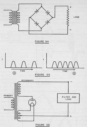
DRY RECTIFIERS
The copper oxide rectifier is a good example of this type. It depends for its action on the fact that the combination of a thin film of cuprous oxide formed on a copper surface offers a low resistance to current flow in one direction and a high resistance for the other direction.
Each oxide film will stand only a few volts in the reverse direction and handle a limited current. Rectifier units are built in stacks of alternate rectifying and lead discs in various combinations. Figure 94 shows a typical circuit using copper oxide units for full-wave rectification.
137
These rectifiers will allow current to flow in both directions if the break-down voltage or breakdown temperature is exceeded. Most power units are constructed with attached cooling fins so that high currents may be handled without exceeding the maximum safe temperature of about 100 degrees Fahrenheit.
Copper oxide rectifiers are frequently found in rectifier-type AC measuring instruments. They are used in low voltage, high current circuits such as battery chargers and vacuum tube cathode heating circuits. They are sometimes used as mixer-detectors in superheterodyne receivers covering low frequencies because they introduce less noise into the circuit than would a vacuum tube.
138
Another type of dry rectifier, the selenium type, consists of an iron disc coated with both selenium and a thin layer of special alloy. The alloy provides a uniform contact surface.
Selenium rectifiers are smaller and lighter than copper oxide rectifiers of the same power handling capacity and can be operated at higher temperatures.
TUBE RECTIFIERS
Tube rectifier systems may be classified according to the type of tube used, the principal types being high vacuum and mercury-vapor tubes. Rectifier systems may also be classified as half-wave and full-wave systems.
139
In a half-wave rectifier, the tube will conduct during one half of each cycle and will not conduct during the other half cycle. Thus current flows half of the time, becoming zero between half cycles as shown in Figure 95-A.
In a full-wave rectifier, separate tubes or separate elements in the same tube are used for each half cycle and pulsating current flows continuously as shown in Figure 95-B.
Figure 96 shows the connections for a half-wave rectifier.
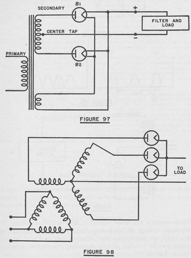
Figure 97 shows a full-wave rectifier circuit. When the upper end of the secondary is positive, the plate of tube No. 1 is positive with respect to its cathode. Current will then flow through tube No. 1 to the filter and load, the circuit being completed through the lead to the center-tap of the winding.
At the same time that the upper end is positive, the lower end will be negative. When this occurs tube No. 2 will offer a high resistance to current and will not conduct. As the polarity of the secondary winding changes during the next half cycle, tube No. 2 will conduct while tube No. 1 will not.
The action of the half-wave rectifier of Figure 98 is similar to that of one tube of Figure 99, the tube conducting on one half cycle and not on the next.
In rectifiers, the peak inverse voltage is the largest negative voltage that can be applied to the plate with safety. The inverse voltage allowable determines the maximum DC voltage that can be obtained from the tube.
High vacuum rectifiers are rugged and not critical as to operating temperature when operated within their ratings. The voltage drop across such a tube is comparatively high.
Hot-cathode mercury-vapor tubes are frequently called simply mercury-vapor rectifiers. They can be considered high vacuum tubes into which there has been placed a small amount of mercury. When the cathode is heated, part of the mercury vaporizes and acts as a source of ions.
The cathode of the tube must reach full operating temperature before plate voltage is applied. The plate potential is normally 15 to 20 volts above the cathode. If the plate voltage exceeds 22 volts, the tube may be damaged by the positive ions striking the cathode. Care must be taken to guard against short circuits and momentary overloads. The tubes may generate radio frequency interference.
The mercury-vapor tube has higher efficiency, better voltage regulation, and requires lower filament power than the high vacuum type. It is used in transmitter power supplies where high powers are required. The high vacuum type is used in receivers.
Figures 96 and 97 are circuits frequently found in receivers. When considerable power is required, polyphase rectifier systems are used.
510493°-43-10
140
There are a great many rectifier arrangements possible in such systems.
Figure 98 shows a. three-phase half-wave rectifier circuit. In such a circuit each tube carries current one-third of the time, and the output wave pulsates at three times the supply frequency. The action of the circuit can be thought of as three half-wave rectifiers with each leg of the secondary operating on one phase of the supply.
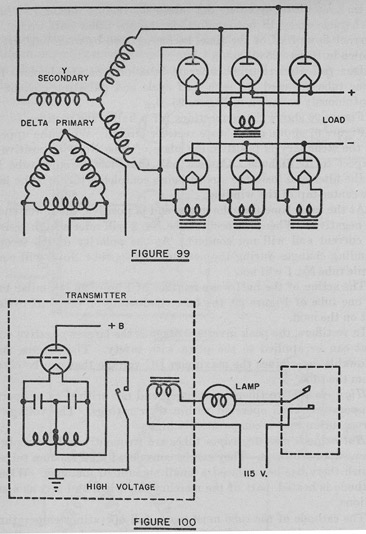
Figure 99 shows a three-phase full-wave rectifier circuit. The arrangement is such that full-wave rectification is obtained from each phase through each leg of the secondary circuit.
141
3.3 Relays
In its simplest form a relay is a switch which is controlled from a distance. The force that operates the relay may be the hand that closes a switch at a distant point, or it may be some circuit effect close to the relay in space, but distant from it electrically.
There are a great many relays of various types. The discussion here will be limited to the relays most commonly used in communication equipment.
Many relays depend on a solenoid for their action. The coil is built around a movable iron core piece that is mechanically connected to the switch system to be used. When the coil is energized or de-energized by current flowing through it, the iron piece within it moves, opening or closing the switch or switches tied to it. There is an almost infinite variety of arrangements that can be thus built up.
Communication equipment relays can be roughly divided into three groups, control relays, protective relays, and operation relays.
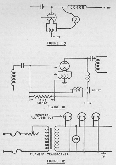
Control relays are used to start and stop motor generators, to open and close plate voltage circuits, and to control the application of power to the equipment. Figure 100 is a sketch of a plate voltage relay circuit. In this simple example the relay is also used to key the transmitter.
In addition to giving a ready means of operating the plate voltage switch from a distance, this relay is also protective in that it allows the operator to control a dangerously high voltage circuit by operating a relatively safe, low voltage device.
Protective relays protect equipment against improper operation. Such relays are frequently well described by their function, as for example, no-voltage, overload, reverse-current, and time-delay relays. Although it is not exactly a relay, the thermal cutout or overload release is a form of protective device. This type depends for its action on the warping of a bimetallic strip, which, when heated above a safe temperature, springs away from a contact and removes the power from the equipment.
The most common operation relays are keying relays. These are devices for keying a transmitter circuit from a safe, remote point. Such relays are used in the keying points of the various circuits discussed under keying in Section 3.13.
RELAY MAINTENANCE
Relays should be carefully inspected regularly. They should be cleaned as often as is necessary to insure against damage or failure. Ordinarily, periodic cleaning with carbon tetrachloride and drying the contact immediately will be sufficient. A small piece of chamois
142
("shammy") leather on a thin strip of bakelite makes a convenient cleaning and drying tool. Paper and fuzzy materials should not be used.
If relays have been properly set and adjusted, cleaning will keep them in shape for a long time.
RELAY TROUBLES
Relay coils are usually single solenoids. In case a relay fails to operate, the coil can be quickly tested for shorts, grounds, or opens; an open coil being the most common failure.
Generally speaking, films forming on the contact surfaces cause the greatest amount of trouble. One important function of the spring pressure on relays is to help the contacts penetrate the films forming on them.
Films will form by action of the air and various other gases on the contact metal, but grease films are responsible for 90 percent of all troubles. Carbon formations, due to the burning of grease and other substances can be troublesome. Carbon will form rings on contacts, eventually building up the rings so that the contacts will be held open.
When current always flows in one direction through a relay, the contacts may "cone and crater." The crater is formed by the metal being transferred to the other contact and deposited there in the form of a cone:
When filing contacts to remove carbon, cones, or craters, it is not desirable to polish them too smoothly. The slight roughness left after filing with a good file helps to break through any films that form. It should be remembered that most files will be greasy and that, after filing, the contacts should be cleaned with carbon tetrachloride.
When ball-shaped contacts are found, they should not be flattened. In many applications ball-shaped contacts are better than flat ones, since dust does not collect on them so readily and the ball points break through films more easily.
Normally operating contacts spark slightly. Useful sparking can be easily seen, but sparking should not be confused with spitting or arcing.
Capacitors should not be shunted directly across contacts because they may be badly burned by the current flow from the condenser. There should be at least one ohm per volt in series with the capacitor.
Relay contacts are actually welded together very slightly every time current flows. Hence, sometimes a relay with a capacitor in series with the contacts will operate better with a few thousand ohms shunted across the condenser. The value used should be as low as possible since it serves only to insure current flowing through the contact just after it closes.
143
Relays require care. They must be operated as designed, with the clearances carefully set and the contact surfaces kept clean. It is worth noting again that grease is the greatest enemy of good contact performance.
3.4 Tuning
As far as the practical operation of communication equipment is concerned, tuning can be defined as the process by which circuits are adjusted to operate with maximum efficiency at a given frequency. Usually, tuning requires the adjustment of circuit capacitance or inductance to resonate the circuit.
In a receiver, the elements are ordinarily ganged together so that, after the receiver has been aligned, the only adjustment possible is very careful setting of the tuning control to secure maximum desired signal.
In transmitters, the various stages are tuned separately. Consequently, tuning for the best results will require thought and care. The parallel-tuned resonant circuit is used in most plate circuits and many grid circuits.
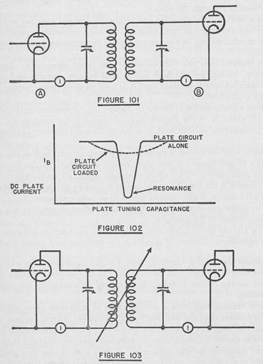
Such a combination is shown in Figure 101. Considering the plate circuit alone, A of the Figure, normal tuning is for resonance. The circuit behavior, as it is tuned, is shown by the solid line curve of Figure 102.
When a second circuit is coupled to the plate circuit, such as the grid circuit B of Figure 101, the plate circuit is affected by the presence of the grid circuit. This effect is usually described as loading. The grid circuit is the load being excited or driven by the preceding stage. The grid circuit is also usually tuned to or near resonance.
The dotted curve of Figure 102 shows the effect of coupling the secondary circuit to the primary.
The DC meters in plate and grid circuits are used to indicate the best operation. Generally speaking, the plate current meter reads a minimum, or shows a "dip", for best circuit adjustment. In addition to showing resonance, the pronounced dip in the plate current that occurs as the circuit is tuned is a general indication of the circuit operation.
Most transmitters have a normal value of minimum plate current. If the current does not decrease in approximately normal fashion it is a sign the stage is not operating properly. Improper operation may be due to excessive circuit losses because some part has changed in value or has otherwise become defective. It may also be due to a lack of proper grid excitation on the stage, which usually means that the preceding stage is not properly tuned.
144
Ordinarily the secondary circuit is tuned so that current is maximum, for then the voltage drop across the circuit elements is maximum and the maximum voltage is available to excite or drive the grid of the tube. It must be carefully noted that for a given transmitter the maximum grid current should be specified, either as a normal value for the transmitter or for the types of tubes used. Whatever value is specified should not be exceeded or the tube will be damaged.
To summarize, the general rules for transmitter tuning include:
(a) Tuning the transmitter stage by stage, starting from the oscillator.
145
(b) Regardless of other metering, DC plate current meters are usually furnished. Tuning should result in "dip" or minimum values as shown by these meters.
(c) When grid current meters are provided, tuning the grid circuits should result in maximum current.
(d) When an antenna RF ammeter is provided, tuning of the last circuit should result in maximum RF current indication.
The rules given can only be general rules, for each transmitter is an individual problem in tuning. Nothing stated here should be considered as changing the instructions given specifically for a particular transmitter.
In addition to the rules and procedures for basic tuning, other points come up from time to time. For example, when a stage is being tuned to the fundamental frequency, there will be a marked dip in plate current. Now when the stage is tuned to act as a frequency doubler, the tuning is changed from the lowest frequency upward and the first dip will be the fundamental. If tuning is continued, the next dip will be the harmonic. Notice that the second, higher frequency dip or minimum plate current value, will be less of a dip, i. e., a higher minimum value than the first. This is because there, is less harmonic than fundamental power available in the circuit.
Generally speaking, transmitters are adjusted for maximum efficiency, that is, to deliver the maximum power to the antenna. The ideal inter-circuit coupling arrangements to accomplish this are shown in Figure 103.
When both primary and secondary can be tuned and the coupling can be varied, as shown in Figure 103, the best tuning and maximum efficiency can be obtained. Unless all three features are controllable, the tuning is a compromise.
In transmitters to be used aboard ship, the circuits are arranged for simplicity. Consequently, the coupling is not very often adjustable in such circuits.
If the coupling is fixed, the designer has set the coupling at an average value that will serve over the range of frequencies covered.
Several other variations are possible. Figure 101 showed fixed coupling and tunable primary and secondary circuits. As previously stated, the primary is tuned for minimum current and the secondary for maximum current.
When only the primary can be tuned, that circuit is tuned to the minimum or "dip." When only the secondary is tunable, tuning is for maximum current.
If ship transmitters do have variable coupling, it is usually found in the circuit between the final amplifier and the antenna. Figure 104 shows such a circuit.
146
In this type of circuit, the coupling should be set at a low value, usually described as "loose" coupling. The primary or plate circuit is then tuned for a minimum or dip. The secondary is then tuned for maximum current. The process is repeated until there is no increase in secondary current.
The coupling is now increased slightly and the primary and secondary tuned as before.
The whole process of increasing coupling, tuning and retuning, is repeated until the primary (final amplifier) plate current is near, but less than, the maximum allowed by the instructions on the transmitter. The coupling is then reduced slightly. Finally, primary and secondary circuits are retuned.
The antenna may be resonant in some installations. To check for antenna resonance, tune the primary to minimum current, or apparent resonance, then open the secondary circuit. If the antenna is resonant to the frequency in use, retuning the primary will now give the same setting as before. If the antenna is not resonant, the primary will tune to a different point with the antenna open.
It usually happens that an untunable, non-resonant antenna is used. Such a circuit is shown in Figure 105.
In this type of circuit, the coupling is adjusted to a low value, i. e., to loose coupling, and the primary is tuned. The coupling is then increased in steps, and the primary retuned after each increase in coupling. It will be seen that the secondary or antenna current increases up to some value of coupling and then starts to decrease. At this point, coupling is reduced slightly and the primary tuned for a minimum. Maximum antenna current will result.
It sometimes happens that interstage coupling is of the form shown in Figure 106, where the primary is not tuned.
In such cases the minimum plate current will occur at a slightly different tuning setting than maximum current in the secondary. For reasons that cannot be explained here, the best tuning point is that which gives minimum plate current rather than the point giving absolutely maximum secondary current.
To summarize:
(a) Study the instructions for each transmitter carefully before attempting to tune it.
(b) As a general rule, tune primary (plate) circuits for minimum DC. Tune secondary (grid) circuits for maximum current.
(c) After tuning primary and secondary, retune primary and secondary.
(d) If time permits, tune through a transmitter once carefully, and then retune the whole transmitter.
(e) Always tune on the lowest power available at first. Check tuning at full power if necessary. Do not radically detune circuits
147
when operating at high power. The tubes may be damaged if plate circuits are far from resonance when full plate voltages are being used.
(f) Always remember that transmitters operate at very dangerous high voltages. Reread and study safety precautions repeatedly.
3.5 Transmitter Servicing
STOP! LOOK! THINK!
Transmitter Voltages Are Dangerous
Always Observe Safety Precautions
Never work on a transmitter with the power on. When the power is on, adjustments may be made only from the front panel.
148
Ground all objects inside a transmitter, especially capacitors, to the transmitter frame or other grounded object with a grounding stick or well insulated screw driver before working on the transmitter.
Check the obvious things first.
Localize the trouble as soon as possible.
Transmitters may be divided into sections for the purpose of localizing troubles.
TRANSMITTER SECTIONS
External circuits:
(a) Radiating system, antenna, lead-in, and ground.
(b) Remote keying.
(c) Remote control (start-stop).
(d) Power supply.
In most transmitters, the panel-mounted meters are usually sufficient to check normal circuit voltages and currents and to indicate abnormal conditions that exist in a particular stage. The effects of one circuit on another may also be seen by observing the meters while tuning. It is only very rarely that portable meters need be used to measure voltage or current.
When portable meters must be used, great caution must be exercised because of the dangerous voltages that may be encountered. Notice carefully that when equipment is supplied with any high voltage, this voltage may appear at unexpected points when failure occurs.
Tuning circuits are generally defective when operation of the tuning controls produces no variation in meter readings.
Tubes are usually tested by substituting new tubes for the old ones. In case of doubt, filament voltages should be checked to avoid destroying the new tubes.
Circuits connected across capacitors may be located at a distance from the capacitor. In checking capacitors for shorts, the associated circuits must be considered.
A skeleton list of likely faults and symptoms is given below. This list is of necessity very general, since several faults may produce the same symptoms. Each transmitter failure is a new problem
149
requiring judgment, a good knowledge of transmitter operation, and analysis.
Equipment instruction books must be studied carefully.
COMMON FAULTS
Transmitter will not start:
1. No line voltage. Switch open or fuse blown.
2. Line voltage low, contactors will not operate.
3. Protective relay tripped.
4. Starting switch defective.
5. Open or short in starting circuits.
6. Interlock open.
Tube filaments heat-no plate voltage:
1. Interlock open.
2. High voltage fuse blown.
3. Plate circuit open.
4. No plate circuit supply. Rectifier or motor generator not operating properly.
5. Plate protective relay open:
Voltage too high.
Tripped by overload.
No grid bias, causing overload.
Improperly adjusted.
6. Voltmeter defective.
7. Tune-operate switch defective on one position or other.
Filaments do not heat:
1. Filament burned out.
2. Loose connection-tube loose in socket, or lead.
3. Filament rheostat defective.
4. Filament supply voltage off:
Transformer winding open.
Motor generator defective.
5. Open or short in supply circuit.
6. Filament meter defective.
Antenna radiation low:
1. Transmitter not properly tuned.
2. Defective tube.
3. Antenna open or grounded.
4. Defective circuit.
5. Antenna current meter defective.
6. Ship close aboard, transmitter tuned to same frequency.
150
No radiation:
1. Oscillator not operating.
2. Transmitter not tuned.
3. Low voltage.
4. Defective tube.
5. Defective keying circuit.
6. Antenna open or grounded.
7. Defective meter.
8. Circuit defect.
Transmitter runs but will not key properly:
1. Keying relay improperly adjusted.
2. Keying relay defective, coil open or shorted.
3. Keying circuit shorted, open, or changed resistor value.
4. Bad hand-key contacts.
Poor note:
1. Keying relay improperly adjusted or dirty.
2. Transmitter unstable, improperly tuned.
3. Defective grid bias supply or resistor.
4. Poor regulation in the voltage supply.
5. Defective filter capacitor.
Frequency unstable:
1. Poor regulation in the voltage supply.
2. Temperature control thermostat defective.
3. Loose connection in oscillator stage.
4. Mechanical vibration of oscillator, shock mountings defective.
5. Oscillator overloaded.
6. Transmitter not properly tuned.
Continuous keying:
1. Hand key accidentally locked.
2. Keying circuit shorted or otherwise defective.
3. Loose or broken relay spring.
4. Relay contacts welded together.
Poor modulation:
1. Poor tube, modulator, or speech amplifier.
2. Improper grid bias, any tube.
3. Defective filter, coupling, or by-pass capacitor.
4. Supply voltages wrong values.
5. Defective microphone.
6. Partially shorted transformer winding.
7. Any defect that can cause distortion in audio speech amplifiers.
8. Dirty relay contacts.
151
No modulation:
1. Bad tube, modulator, or speech amplifier.
2. Defective microphone cable, open circuit or poor connection.
3. No voltage supply.
4. Circuit defect such as, open or shorted transformer, open capacitor or resistance.
5. Defective relay.
6. Defective microphone.
SERVICING PROCEDURE
Transmitter fails to start:
1. Try starting from another position.
2. See that power switches are closed:
Local control switch.
Starting panel line switch.
Distribution board switch.
3. Check fuses:
Starting panel.
Distribution board.
Power supply units.
4. Check interlocks on all units.
5. Check starter panel overload relays, or rectifier overload relays.
6. Measure line input voltage to starting panel of motor generator or rectifier power supply. Line voltage may be low.
7. If relays and fuses are normal and line voltage is normal, open the line switch and check continuity of starting contactor solenoid.
8. If contactor solenoid is normal, check starter box circuit, using circuit diagram.
9. If starting contactors close but motor does not run, open line switch and check motor starting resistors with ohmmeter. These resistors are often behind the panel.
10. If power supply starts but fuse blows at once, check output circuit for short. Never attempt to measure power supply high voltage DC output.
11. To check quickly for a short causing overload, pull line switch, disconnect power output leads, and measure circuit resistance as shown in Figure 107. An ohmmeter may be used, but it is best to use a megger on the high voltage DC circuit. Check the resistance reading obtained with the circuit values on the equipment schematic diagram.
12. If a short circuit is indicated, care is required in interpreting the result. There may be several parallel circuits as shown in the example of Figure 108.
152
The short may be in any of the three parallel circuits connected to C and D or in the lines A and B. Disconnect A and B and measure the resistance between them.
If A and B are not shorted, circuits 1, 2, and 3 are disconnected one at a time and tested to isolate the bad circuit.
If A and B are shorted, check the motor generator filter capacitors as shown in Figure 109, taking care to disconnect the filter so that tests will be made through the filter and not around it. An ohmmeter set to its highest resistance scale may be used for a quick test. The condensers normally have fairly high capacity, so that the ohmmeter needle will kick markedly and slowly return to zero if the capacitors are good.
153
If the short between A and B is not in the filter capacitors, then the armature and field coils of the motor generator set must be tested. Procedures for such tests are described in Section 3.21.
13. In rectifier power supplies, the output circuits can be checked as described above. When it is necessary to check back into the rectifier and its filters, consult Sections 2.34 and 3.22.
Tube Filaments heat-No plate voltage:
1. Two different symptoms are usually found in this case. Sometimes plate voltage does not reach the transmitter at all. Sometimes voltage reaches the transmitter but the overload relay quickly trips out.
2. If voltage does not reach the transmitter, check the high voltage supply unit is outlined in the previous section.
3. If the supply unit is operating, open the line switch and check high voltage fuses, reset overload relay, etc. Inspect switches.
4. If voltage still does not reach the transmitter, check the supply and high voltage output circuits for open-circuit conditions along the lines indicated in the preceding section.
5. If the overload relay trips out after having been reset, open the line switch and check the setting of the overload relay to make sure it will trip at the correct current value.
6. A defective tube may cause the overload that trips the protective relay. Sometimes this tube can be detected by the faint blue glow, or flash, that occurs during the short time the plate voltage is on the tube. Such a tube may be gassy or have an inter-element short.
7. If the trouble has not been discovered, measure the resistance between plate and filament as indicated in Figure 110. The resistance should be quite high. Check the value obtained against the circuit elements as shown on the circuit schematic diagram. Take care to see that the line to the plate voltage supply is open as well as the power supply line, to prevent a misleading test by including the generator in the circuit.
8. When the resistance measures too low, check all filter blocking and by-pass capacitors. Check switches. Test for grounded or shorted leads.
9. Next measure the grid bias voltage at the terminal strip or at the power supply. Remember that ground is positive in a bias circuit. Do NOT measure the bias at a tube socket or any point near a high voltage terminal.
154
10. The supply must be checked if the bias voltage delivered is not correct. The bias circuit must be checked for continuity and resistance, if the supply is satisfactory. Changed value and intermittently open resistors are frequently found in bias circuits: In some equipment, the bias voltage also energizes a plate voltage relay as shown in Figure 111. This arrangement is designed to protect the tube from overload due to loss of bias by opening the plate line when the bias goes out.
155
11. A defective plate voltmeter will seldom affect the transmitter operation. Usually, when the voltmeter fails, the correct plate voltage can be maintained by adjusting the voltage so that normal plate current results. This cannot be done unless the normal transmitter meter readings have been recorded.
Plate voltage-no filament heating:
1. If only one tube is out and voltmeter shows proper filament voltage, replace tube with spare.
2. If more than one tube is not lighted, or voltmeter shows no voltage, check fuse in filament supply.
3. Next remove all tubes and check for continuity between the two filament prongs as indicated in Figure 112. This measurement will indicate low resistance because the transformer secondary is in the circuit.
4. If the circuit is open, check for loose or broken leads and open-circuit transformer secondary.
5. If the circuit is shorted, disconnect transformer and test for shorts, noting that one side of the filament circuit should be grounded.
6. Check filament rheostat for open circuit.
No Radiation:
1. Radiation ammeter may be defective. Transmitter can be used by tuning the power amplifier for minimum plate current and then tuning the antenna circuit for highest minimum plate current.
2. Keying relay not operating. Some meters should show variation in readings if keying is occurring. Watch relay while transmitter is being keyed. It may be necessary to check relay for proper closure with an ohmmeter after the power has been shut off.
3. Transmitter not tuned properly. Frequently tube plates will glow dull red in such cases.
4. Antenna open or grounded. Check band switch, inductance switch, and disconnect switch. Check for wrong inductance tap setting.
5. Oscillator not operating. In this case, as in failure in other stages, normal meter readings should be at hand for comparison. \Try transmitter on another band. Check band switches and other mechanical features for defects. Replace oscillator tube. Check plate, grid, and screen circuits for continuity, measuring from the tube socket to the proper power supply terminal. Resistors are apt to be defective.
510498°-43-11
156
Check all circuit parts, using the schematic diagram for reference. In case the coupling of the amplifier to the oscillator is variable, the oscillator may be overloaded. Reduce coupling and tune the oscillator.
6. When a stage or stages fail to draw plate current, check for a defective tube or open grid or plate circuit. When any circuit does not show change in meter readings when tuned, the trouble is usually in a tuning circuit if the stage is getting the proper voltages from the supply.
Low radiation:
1. Compare meter readings with the normal readings for the transmitter. Usually the defective stage will be indicated by abnormal readings.
2. If all other readings are normal, radiation ammeter may be defective or there may be a ship close aboard with a transmitter tuned to the same frequency. A bridge or pier structure may also absorb some radiation.
3. Retune transmitter. Out-of-resonance operation is often shown by the tube plates overheating.
4. Check antenna switch and inductance tap. Check antenna circuit for partial ground or high resistance connection. Use a megger to test for grounds. Test for continuity through the antenna trunk with an ohmmeter, using low resistance scale.
5. If a stage appears defective, put in another tube. Also try transmitter on another band, or operate band switch several times in case switch is not making good contact.
6. Usually no meter variations occur if tuning circuits are defective.
7. Check all mechanical contacts, band switches, etc. for partial grounds or high resistance connections.
8. In starting to check components such as resistors and capacitors, first take continuity readings between the tube plate, grid, and screen socket terminals and power supply terminal board to test for high resistance connections. Check values with schematic diagram.
9. Check all parts in defective stages as well as wiring for partial shorts, grounds, and opens.
Transmitter runs but will not key properly:
1. Try keying from another position. Do not forget test key on transmitter panel. Check defective keying leads for short or ground. Check any fuses that may be in the circuit.
2. Watch operation of keying relay while transmitter is being
157
keyed. If relay is operating, contacts may be dirty or improperly adjusted.
3. If relay is not operating, cut off power and check main keying relay and any others in the circuit for adjustment and condition of contacts.
4. Check keying circuit control voltages.
5. Test keying circuit and control circuit for continuity, checking all resistors for proper values. Use schematic diagram as reference.
6. If keying and control circuits are operating normally, check grid circuits of the amplifiers being keyed, especially the resistors used.
Poor notes:
1. Transmitter not properly tuned.
2. Keying relay contacts dirty or improperly adjusted. Spring tension not sufficient, closure too light.
4. Defective grid-leak resistor in oscillator circuit.
5. Defective grid bias resistor. Resistor should be removed for test, if possible, noting that intermittently bad resistors will sometimes check normal when cool.
6. Intermittent or variable ground of some part or lead in oscillator circuit.
7. Varying oscillator plate voltage. Poor regulation of supply due to defective speed regulator, dirty commutator, sticky brush, etc.
8. Oscillator coupled too tightly to next stage. When coupling is variable, try a reduced value.
9. Strong, nearby transmitter may be producing an interfering signal.
Continuous keying:
1. Check hand keys at all positions for key accidentally locked or weighted down. Check for speed key (bug) with shorting switch closed.
2. Transmitter panel test key stuck.
3. Check keying relay for broken spring or welded contacts.
4. Look for short in control lines to keying circuit.
5. Open line switch and check keying circuits and keyed amplifier circuits for opens, shorts, and grounds. Use schematic diagram for reference.
Frequency unstable:
1. Retune transmitter.
2. Check for defective oscillator tube by replacing tube.
3. Look for loose shielding around oscillator circuit, especially when there is vibration or excessive rolling of ship.
5. Check through oscillator circuit for loose connections or variable grounds.
MODULATION TROUBLES
It will be seen by examining the list of more frequent failures in modulation systems on page 150, that most defects can be located by routine testing.
However, some of the troubles peculiar to modulation are indicated in the behavior of the plate current of the modulated amplifier.
In plate modulation, the DC plate current of the modulated amplifier should remain constant. If the plate current meter kicks downward during modulation:
1. Grid bias on the amplifier may be too low.
2. RF excitation, or input, to the modulator may be too low.
3. The load on the modulated amplifier, i. e., the next stage, may be improperly coupled and adjusted or changed in value.
4. Filament voltage may be low, or the tubes badly overloaded.
An upward kick of the plate current meter of the modulated amplifier may indicate:
1. Overmodulation, i. e., excessive audio power.
2. Parasitic oscillations in the modulated amplifier.
Amplifier plate current may drop during modulation when the voltage regulation is poor, i. e., when the supply voltages do not remain constant under load. This poor regulation may occur in the plate power supply, especially when the same plate supply is used for all sections of the transmitter. It may also occur due to AC line voltage variation. When it is the supply line that is varying, the change should show up on the filament voltmeter or on any voltmeter across the AC line.
In grid modulation, the modulated amplifier plate current should be very nearly constant. If there is a pronounced downward kick - during modulation:
1. RF excitation may be too great.
2. Amplifier grid bias may be too low.
3. There may be distortion in the modulator or speech amplifier.
4. The amplifier load may not be properly coupled or adjusted or may have changed in value.
When the plate current kicks upward during modulation:
1. There may be overmodulation due to too high audio amplification.
2. Speech amplifier may be distorting.
3. The grid bias of the amplifier may be too high.
159
4. There may be parasitic oscillations in the modulated amplifier.
Downward variations in modulated amplifier plate current should be regarded as suspicious in all cases because of the danger the modulated amplifier may be overloaded due to low or zero grid bias. In such a case the tube may be damaged very quickly by the overload.
MISCELLANEOUS TRANSMITTER TROUBLES
Insulation failures in high voltage RF insulation are frequently audible as "spitting" or "crackling" sounds when the RF current jumps the gap due to the damaged insulation.
When the damaged point is hard to locate by sound, the transmitter room can be darkened and the break located by the blue spark of the flashover.
Damaged parts or leads should be replaced with a spare part or a lead of the same material. The insulation on a lead must be replaced with high voltage resistant material when it is necessary to make a repair. Ordinary friction or rubber tape is seldom satisfactory. Silk tape or empire cloth can be used in an emergency.
In an emergency, it may be practicable to remove the charred, damaged insulation and move the affected lead well clear of surrounding objects thus using air as an insulator. Such a temporary repair should be permanently fixed as soon as possible.
When transmitter plate or filament voltages are unsteady, the ordinary power supply defects should not be overlooked. Such defects may be dirty collector rings or commutators, and worn, loose, or broken brushes.
Sometimes a power amplifier will heat up excessively when the key is closed, even though the amplifier and antenna circuits are properly tuned. The plate current will be high in such a case.
When heating is due to a gassy tube, the condition may sometimes be recognized by the bluish glow in the tube. Failing this symptom, the plate voltage may be too high.
In some transmitters with variable coupling, the heating is due to overloading the final stage by having the antenna too tightly coupled. The coupling should be reduced in such a case, bearing in mind the fact that normal plate current must be maintained in the power amplifier.
Sometimes a transmitter will behave properly while the key is closed but will continue to radiate with the key up. Such symptoms usually indicate biasing troubles. The bias supply, bias resistors, and grid circuits should be checked.
An amplifier tube may be defective and so not be properly biased by perfectly normal bias voltages. There may also be a ground on the keying circuit.
160
When a transmitter indicates that it is radiating but no signal is heard, the obvious defect must not be overlooked. The transmitter should be checked carefully to insure against an error in setup with the result that the transmitter radiates in the wrong frequency band.
Some transmitters require neutralization, especially when triodes are used. The neutralization is necessary to compensate for stray coupling and feedback from plate to grid circuits.
In such a case, the transmitter may break into oscillation at or near the operating frequency, independently of the oscillator.
Whenever the transmitter instructions call for neutralization, the procedure specified should be carefully followed to avoid difficulties.
The procedure for servicing transmitters may be summarized as follows:
1. Each type of transmitter is a new problem. The instruction books, and wiring and circuit diagrams must be carefully studied.
2. In testing transmitter circuits, the blueprints are well nigh indispensable because parts of a circuit may be located at a distance from the obvious components.
3. The fundamentals of oscillators, tuned circuits, and vacuum tubes must be borne in mind. Many transmitter circuits are simple examples of fundamental principles.
4. In servicing transmitters, STOP!, LOOK!, and THINK:FIRST. Even the smallest transmitters use voltages that are DANGEROUS.