Notes on Servicing Radio and Sound Equipment, 1942, is a training manual that introduces the art of tube radio and sound equipment repair. This included both receivers and transmitters, and the motor generators they use.
In this online version of the manual we have
attempted to keep the flavor of the original layout while taking advantage
of the Web's universal accessibility. Different browsers and fonts will cause
the text to move, but the text will remain roughly where it is in the
original manual. In addition to errors we have attempted to preserve from the original,
this text was captured by a combination of optical character recognition
and human typist. Each method creates errors that are compounded while
encoding for the Web. Please report any typos, or particularly annoying layout issues to the Mail Feedback Form for correction.
Richard Pekelney
Webmaster
Notes on
Servicing Radio and Sound
Equipment
U. S. NAVY
WEST COAST SOUND SCHOOL
WEST COAST SOUND TRAINING SQUADRON
SAN DIEGO, CALIFORNIA
II
RESTRICTED
NAVY DEPARTMENT
OFFICE OF THE CHIEF OF NAVAL OPERATIONS
WASHINGTON
1. This publication, Notes on Servicing Radio and Sound Equipments, U. S. Navy, published by the West Coast Sound Training Squadron, West Coast Sound School, San Diego, California, is hereby adopted as standard publication for the U. S. Navy.
2. "Notes on Servicing Radio and Sound Equipments" is a restricted publication and is furnished for the information of commissioned, warrant, and enlisted personnel of the Navy, whose duties involve design, instruction, operation and installation of radio and sound equipment. The word "restricted" as applied to this instruction pamphlet signifies that it is to be used only by the above personnel and that the contents of it are not to be made known to other persons. Additional copies may be obtained from the Readiness Section, Headquarters, Commander-in-Chief, United States Fleet.
F. H. HORNE.
III
FOREWORD
"NOTES ON SERVICING RADIO & SOUND EQUIPMENT" is a revision of the original Fleet Sound School, San Diego, publication "Notes on Servicing Communication Equipment" and was prepared by the Material Staff of the West Coast Sound School as a textbook for the first six weeks of the Sound Material Course. It is used in conjunction with the Sound Material Handbook which is used as a textbook for the last four weeks of the Sound Material Course. This pamphlet is designed to present in a compact form the basic fundamental radio principles required for the servicing of sound equipment.
It is hoped that this pamphlet, although not specifically designed for that purpose, will prove useful as a reference book to men in the naval service who are engaged in servicing radio and sound equipment.
Constructive criticism will be welcomed.
A. D. BURHANS, Captain, U. S. Navy, Commander, West Coast Sound Training Squadron, Officer-in-Charge, West Coast Sound School.
IV
UNITED STATES FLEET
HEADQUARTERS OF THE COMMANDER IN CHIEF
NAVY DEPARTMENT, WASHINGTON, D. C.
NOTES ON SERVICING RADIO AND SOUND
EQUIPMENT
Distribution.-Standard Navy Distribution List (Part 1-#8; Part 2-#7)
List One.-b, c, d, e, f, g, h, i, j, k, 1, m, n, o, p, q, r, s, t, u, w, x, y, z, aa, bb, cc, dd, ee, ff, gg, ii, jj, kk, 11, mm, nn, oo.
List Two.-e, f, g, h, 1, j, s, u, v, x.
List Three.-a, b, c, d, e, f, g, h, j, k, 1, m, n, o, p, q, r, s, t, u, v, w, x, y, z, bb, cc, dd, ee, ff, gg, ii, jj, kk, 11, mm, oo, pp, rr, ss, vv, tt, uu, ww, xx, yy.
List Four.-a, b, d, f, g, i, j, k, 1, o, p, t, x, z, aa, dd, ff, gg, ii, jj, kk, mm, qq.
List Six.-a, b, c, d, e, f, g, h, i, j, k, 1, m, n, o, p, q, t.
List Seven.-a, la, c, d, f, g, h, 1, y.
List Eight.-j, aa.
List Nine.-a, b, c, d.
Aircraft Radioman Training Unit, Atlantic.
Commanding Officer, USN Radio and Sound Laboratory, Navy Yard:-New York, N. Y.; Boston, Mass. ; Charleston, S. C. ; Pearl Harbor, T. H.; Philadelphia, Pa. ; Portsmouth, Va.; and Washington, D. C.
Director, US Naval Research Laboratory, Anacostia Station, Wash., D. C.
O-in-C, -USN Underwater Sound Laboratory, Ft. Trumbull, New London, Conn.
Fleet Service Schools:
Radio Materiel, NOB, Norfolk, Va.
NTSch (Aviation Radioman) NOB, Norfolk, 17a.
Radar School, Nyd, Charleston, S. C.
Radar School, Nyd, Mare Island, Calif.
Radar School, Nyd, New York, N. Y.
Radar School, Nyd, Norfolk, Va.
Pacific Fleet Radar School, Nyd, Pearl Harbor, T. H. Radar School, Nyd, Philadelphia, Pa.
Radar School, Nyd, Portsmouth, N. H.
Radar School, U. S. Destroyer Base, San Diego, Calif.
Radar School, Naval Drydock, Bldg. No. 16, South Boston, Mass. Radio School, U. S. Submarine Base, Pearl Harbor, T. H.
Fleet Sound School, Key West, Florida.
Submarine School, Submarine Base, New London, Conn.
BuAero ; BuShips ; Comd't US Marine Corps; Comd't US Coast Guard.
In order to avoid unnecessary words, the following abbreviations are used:
A (or A battery)
Filament supply battery or source.
a
Amperes.
AC
Alternating current.
AF
Audio frequency.
B (or B battery)
Plate supply battery or source.
C (or C battery)
Grid bias supply battery or source.
cps
Cycles per second.
CW
Continuous waves.
db
Decibel.
DC
Direct current.
EF
Filament or heater voltage.
Eg
Grid voltage.
EK
Cathode voltage.
Ep
Plate voltage.
Esg
Screen grid voltage.
f
Frequency.
h
Henry.
HF
High frequency.
Ib
Bleeder current.
IF
Intermediate frequency.
Ig
Grid current.
Ip
Plate current.
Isg
Screen grid current.
Kc
Kilocycle.
kw
Kilowatt.
ma
Milliamperes.
M
Thousand (multiplier).
Mc
Megacycle.
Meg
Megohm.
mfd
Microfarad.
mh
Millihenry.
mmfd
Micromicrofarad.
mv
Millivolt.
mw
Milliwatt.
Open
Open circuit.
Ω
Ohm.
RF
Radio frequency.
RFC
Radio frequency choke.
Short
Short circuit.
UHF
Ultra-high frequency.
v
Volt (volts).
w
Watt (watts).
2
SYMBOLS
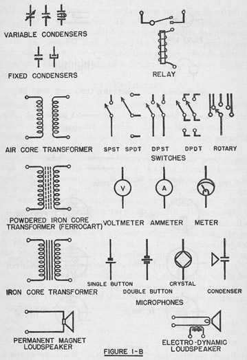
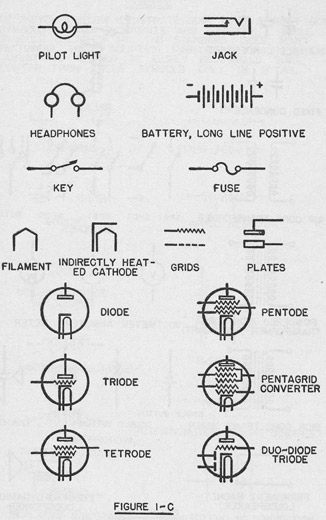
THE SKETCHES BELOW ILLUSTRATE SOME OF THE MOST COMMON SYMBOLS USED IN BLUEPRINTS AND DIAGRAMS. WHILE THE SYMBOLS SKETCHED ARE THE STANDARD ONES, MANY MANUFACTURERS HAVE ADOPTED VARIATIONS OF THEIR OWN. THE VARIATIONS SHOULD BE EASILY RECOGNIZED SINCE THEY DIFFER FROM THESE SYMBOLS ONLY IN DETAIL.
3
4
5
CIRCUIT COMPONENTS
Many junior radiomen are unfamiliar with the standard radio circuit parts or components. In addition, information as to the characteristics of such standard parts is not readily available aboard ship. In the sections that follow, the major components are described, together with brief data on their ratings, characteristics, and appearance. The listings are of necessity representative rather than complete.
1.1 Resistance
Resistance is introduced into electrical circuits by units which are generally designated as resistors. The resistors used in radio circuits are of two types, fixed and variable. Due to the differences in construction, resistors can also be divided into two groups according to their power handling capacity.
Power rating.-Resistors are designed to dissipate a given amount of heat without being destroyed or having their characteristics changed. This power rating is stated in watts, and is the amount of electrical power that the resistor can convert into and throw out in heat without its temperature exceeding a safe value. Since the conditions around the resistor vary and seldom will be exactly those specified in the rating, a large factor of safety should be allowed, that is, a resistor should have a power rating greater than the power which will actually be consumed in it. It is recommended that a resistor which is to be used in a confined space have a power rating of about four times the actual power dissipated.
Tolerance.-To manufacture resistors of exact value would be unduly expensive. Therefore, it is customary to allow the manufacturer a tolerance, or variation from the nominal value of the resistor. For various forms of resistors these tolerances are:
General
±20%, ±10%, or ±5%
High current (especially wire wound)
± 5%
Precision (meter shunts, etc.)
±1% (or less)
The use to which the resistor is to be put determines the allowable tolerance. Thus, a meter shunt of a few ohms would have to be very accurate, whereas a grid leak of several megohms would not be affected by a variation of 10 percent. The tolerance must be taken into account in checking equipment, so that good resistors will not be needlessly discarded, and critical ones will be replaced.
6
At present, the manufacturers are required to produce fixed and molded resistors within a tolerance of 20 percent. In most cases, resistors are actually within 10 percent of the stated value.
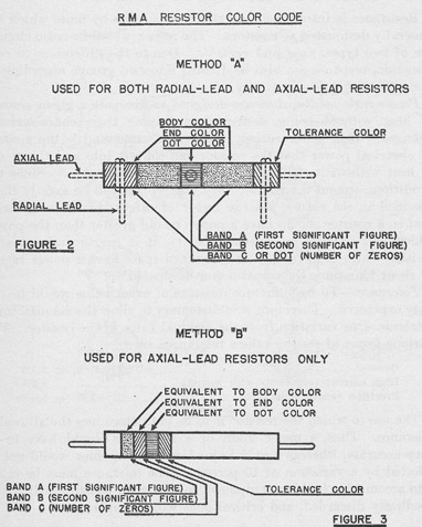
Identification.-Physically large resistors, such as wire wound power types, usually have their resistance in ohms and power rating in watts stamped on some part of their metal fittings or stenciled on the covering material. Small sized, fixed resistors are identified by a standard color code of painted colors marked on them. Figure 2 illustrates the method of marking and lists the numbers equivalent to the colors used.
Due to changes in the manufacturing methods of recent years, the radial-lead resistor has been replaced to a considerable extent by the axial-lead type. In 1938 the manufacturers adopted the system of Method B of Figure 3 for marking axial-lead resistors only. The
7
colors used are the same in both methods, the difference being in the way the colors are applied. Both types will be found in service equipment.
Most resistors will be found to have no tolerance color marking. In resistors manufactured before 1938 this means that the tolerance allowed was 10 percent. In later resistors, the tolerance is 20 percent. Figures 2 and 3 give the tolerance markings under the present system. In case of doubt as to when the resistor was manufactured, the resistor should be measured and the circuit diagram consulted as to the proper value. To avoid confusion on an unimportant point, the tolerance markings under the old method are not given. Notice that the present tolerance colors apply to both types of resistors.
RMA COLOR CODE
Color used on body, end, or bands:
1st or 2d significant figure
Number of ciphers after the first two significant figures
Black
0
None
Brown
1
0
Red
2
00
Orange
3
000
Yellow
4
0000
Green
5
00000
Blue
6
000000
Violet
7
Gray
8
White
9
No tolerance color
± 20%
Silver tolerance color
± 10%
Gold tolerance color
± 5%
EXAMPLES
In the number 62,000, 6 is the first significant figure, 2 is the second significant figure, and the number of ciphers after the first two significant figures is 3.
Resistance (ohms):
Band A
Band B
Band C
2 0
Red
Black
Black
3 9 0
Orange
White
Brown
4 7 00
Yellow
Violet
Red
5 6 000
Green
Blue
Orange
6 8 0000
Blue
Gray
Yellow
7 5 00000
Violet
Green
Green
1 0 000000
Brown
Black
Blue
It should be emphasized that when band C is black there are no zeros following the second significant figure. This is illustrated in the example above for a resistance of 20 ohms.
8
TYPES OF RESISTORS
(a) Fixed resistors, low power.
Power rating.-Standard-1/4, 1/2, 1, 2, and 5 watts.
Range.-From 1 ohm to 20 megohms, varying with type.
Construction.-(1) Molded carbon.-Carbon and clay pressed into a rod or stick. Pigtail connectors wound around or embedded in ends. The resistance is determined by the ratio of carbon to clay.
(2) Film or metallized.-Metal or carbon film deposited on glass or ceramic ("china") tube. Enclosed in ceramic tube. Metal end caps sealed on, with pigtail connectors.
(3) Composition.-Carbon and other resistance material molded at high heat and sealed into insulating compound. Pigtail connectors usually embedded in the ends.
(4) Wire wound.-Either resistance wire wound on fibre or other insulating strip, or wound on plastic rod, sealed in plastic insulating material. May have metal lugs or connectors, or pigtails sealed into the ends.
(b) Fixed resistors, power handling.
Power rating.-Up to several hundred watts.
Range.-From less than one ohm to 250,000 ohms.
Construction.-Wire wound.-Resistance wire wound on ceramic tubing. May be bare wire, vitreous enameled, or cement washed. Vitreous covering is glazed and shiny. Cement covering resembles building cement. Purpose of covering principally to protect wire from mechanical damage. May be metal end, to fit into clips, or have end lugs, or pigtails. Wire wound resistors are frequently tapped, that is, they have connections consisting of metal connectors at various points between the ends and hence at values of resistance lower than the whole unit. A new bare wire type has metallized strips wound around form. Bare types are for use in very protected locations.
(c) Variable resistors.-Variable resistors are often called rheostats or potentiometers depending on whether they are used to control current or voltage. They are also frequently named for their function as for example, volume controls.
Taper.-The word "taper", as applied to variable resistance controls, means that the resistance of the control does not vary in direct ratio to the rotation of the control. The word "linear" means that the resistance of the control does change in direct proportion to the rotation. That is, in a linear control, for 1/4 rotation, there is 1/4 of the resistance inserted in the circuit; and for 1/2 rotation, there is 1/2 of the resistance inserted. However, in a tapered control, 1/2 rotation may only introduce 1/5 of the total resistance. Tapered controls are usually used in circuits as volume control units, because
9
the human ear is so peculiarly built as to make changes occurring in a non-uniform fashion seem to be uniform changes. By custom, "linear" or direct ratio controls are described as "linear taper", though strictly speaking such a name is incorrect. The true tapers are "right hand", and "left hand", depending on which way they are rotated to obtain full volume. The various degrees of taper need not concern us here. The regular replacement spare parts are supplied with the proper taper. In using emergency replacement parts the correct taper must be secured, if the circuit is to operate normally.
Power rating.-Potentiometers, including volume controls, are voltage devices and are seldom capable of handling more than a few watts. Rheostats can be built to handle hundreds of watts but in radio equipment are seldom found with ratings over 100 watts.
Range.-Rheostats-1/4 ohm to 100,000 ohms. Potentiometers-1 ohm to 5 megohms.
Construction.-Resistance wire wound on insulting strips. Also carbon compound or a metallized film on a base plate. The moving contact may be a sliding, rotating arm, or an arm driving a roller.
1.2 Capacitors or Condensers
Capacitance is introduced into electrical circuits by components generally designated as capacitors, or condensers. The capacitors used in radio circuits can be divided into two groups, fixed and variable. The essential characteristics of all capacitors are the voltage rating and the capacity.
Voltage rating.-The insulating material between the plates of a, capacitor is called the dielectric. For every dielectric there is some value of voltage required to break down the dielectric and short out the capacitor. Obviously a capacitor must be selected to have a break down voltage that is higher than any voltage in the circuit in which it is to be used. Manufacturers specify the safe working voltage that may be used without casualty. Capacitors are usually rated in terms of the safe maximum continuous DC voltage and the maximum AC or "surge" voltage with which they may be used. The AC rating usually appears to be less than the DC rating because of the, fact that the peak AC voltage must be considered. A typical rating might be 1 mfd-2500 volts DC; 1800 volts AC. Capacitors should never be used in circuits where the voltage will exceed the safe working voltage because the breaking down of a capacitor may allow currents to flow that will seriously damage other circuit components.
Tolerance.-The general percentages of manufacturing tolerance that apply to resistors apply to capacitors. A capacity variation of ±10 percent from that marked on the unit can be expected.
10
Identification.-Large capacitors usually have marked on them their capacity and voltage rating. Small fixed capacitors may be so marked but are often color coded much as resistors are color coded. The same ten colors are used in this code and they represent the same numbers, that is:
Color:
Code
Color:
Code
Black
0
Green
5
Brown
1
Blue
6
Red
2
Violet
7
Orange
3
Gray
8
Yellow
4
White
9
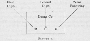
The order in which the dots are to be read is sometimes indicated by an arrow, by placing the capacitor so that the dot nearest the end is on the left, or placing it so that the manufacturer's name reads normally.
The digits indicate the value in micromicrofarads. In Figure 4, for example, if the colors were red-green-black, the capacity would be 25 mmfd. The black dot indicates that no zeros follow. The 7.5 mmfd (.0000075 mfd) capacitor is the sole exception to the system, being coded black-violet-green.
TYPES OF CAPACITORS
(a) Capacitors, variable, air dielectric.
Voltage rating.-From 500 to 20,000 volts DC depending on the air gap or plate spacing, and the construction.
Range.-From 0.5 mmfd to 500 mmfd.
Construction.-Metal plates in two sections, a fixed section supported on insulating material, and a rotating section on a shaft. When turned, the rotating plates mesh with the fixed plates, the capacity in the circuit varying with the angle of rotation. If unmarked, the capacity value cannot be determined accurately by looking at the unit, but in medium sizes a 7-plate capacitor is usually 150 mmfd and a 17-plate equal to 350 mmfd, maximum value. This
11
type never reaches zero capacity, but has a fixed minimum value depending on the construction.
(b) Capacitors, variable, mica dielectric.
Voltage rating.-Low voltage usually not over 500.
Range.-From 3-30 mmfd to 060-2100 mmfd.
Construction.-Ceramic or plastic base, metal plates, mica insulation, adjustment made with machine screw. Usually called trimmers.
(c) Capacitors, fixed, mica.
Voltage rating.-Up to 5000 volts DC.
Range.-0.000025 to 0.01 mfd.
Construction.-Metal foil plates, mica dielectric. Better types moulded into Bakelite or similar plastic. May have soft metal tinned pigtail connectors or machine screw terminals.
(d) Capacitors, fixed paper.
Voltage rating.-Up to 600 volts DC.
Range.-0.0001 to 8 mfd.
Construction.-Metal foil plates with special paper dielectric. May be cased in metal or cardboard, wax filled or moulded in plastic. Usually have pigtail or wire connectors.
(e) Capacitors, fixed, oil impregnated.
Voltage rating.-Up to 2000 volts DC.
Range.-0.002 to 0.1 mfd.
Construction.-Similar to fixed paper except that the paper has been impregnated with insulating oil, thus allowing a higher working voltage.
(f) Capacitors, fixed, oil filled, medium voltage.
Voltage rating.-Up to 5000 volts DC.
Range.-1 to 4 mfd.
Construction.-Usually metal foil and impregnated tissue paper, in oil filled can, with ceramic insulated terminals. Frequently trade marked "Dykanol", "Pyranol", etc.
(g) Capacitors, fixed, high voltage, large.
Voltage rating.-Tested-25-50,000 volts AC.
Range.-0.00003 to 0.05 mfd.
Construction.-Very carefully built of mica and metal foil plates, oil filled metal or ceramic cases, with metal or ceramic supported terminals depending on the case material.
ELECTROLYTIC CAPACITORS
The action of the capacitors described above is fairly easy to understand on the basis of the usual theory because it is easy to understand the formation of the plates and dielectric. On the other hand the operation of the electrolytic capacitor is not so obvious. This type depends on the fact that when a suitable metal, such as aluminum, is
510493°-43-2
12
placed in an electrolyte, such as a borax solution, current will flow freely from the electrolyte to the metal but very little current will flow from the metal to the electrolyte. The combination thus acts as a form of rectifier. By observing polarity, and by placing such components only in DC or pulsating DC circuits, a useful capacitor results. The dielectric in this case is the thin film of oxide and gas formed on the metal and not the electrolyte itself. The polarity must be observed in making connections or the capacitor will be destroyed. Such units are self-healing to a certain extent. A moderate voltage surge, quickly removed, may puncture the dielectric but the film will re-form and restore the capacitor.
(h) Capacitors, fixed, wet electrolytic.
Voltage rating.-25 to 600 volts DC.
Range.-4 to 40 mfd.
Construction.-Aluminum can filled with electrolyte with a center electrode, sealed in with rubber compound. A check valve allows gas to escape. The electrolyte can be spilled. Arrangement resembles a lead-acid B battery cell.
(i) Capacitors, fixed, dry electrolytic.
Voltage rating.-25 to 600 volts DC.
Range.-2 to 50 mfd.
Construction.-Aluminum sheets layered with electrolyte soaked gauze, packed in an aluminum can which may be covered with paper or other insulation. Is "dry" in the sense that a "dry cell" is dry.
(j) Capacitors, fixed, high capacity, low voltage.
Voltage rating.-12 to 50 volts DC.
Range.-Up to 400 mfd.
Construction.-Dry electrolytic.
CIRCUIT COMPONENTS
1.3 Inductances
Inductance is introduced into electrical circuits by components usually described as inductors or inductances. The inductances used in radio circuits are of two general types, fixed and variable. They are further divided into space (air) cored and material (iron) cored. They are usually grouped by their functions, as for example, RF transformers and chokes.
Rating.-Power handling types such as line power transformers are rated according to their current carrying capacity and the voltages which they are designed to use and produce. Chokes are rated by their inductance and current-carrying capacities. RF transformers are usually described by the range of frequencies over which they are useful.
13
Identification.-Inductances are identified by their construction, size, weight, and manufacturers' markings. The leads on some transformers can be identified by the color coding of the wire coverings. The present standard code is as follows:
Interstage and output transformers:
Single primary-Single secondary:
Primary.-Red-plate voltage, Blue or yellow-plate.
Secondary.-Green-grid or high side of moving coil. Black-negative return or low side.
Tapped primary-Tapped Secondary:
Primary.-Red-plate voltage and center tap. Blue-plate, Brown-plate.
Secondary.-Green-grid or high side of moving coil. Black-negative return or low side. Yellow-grid.
Power transformers:
Primary.-Black. Common of tapped primary.-Black. Primary tap.-Black and yellow. Finish of primary.-Black and red. Secondary plate leads.-Red. H. V. center tap.-Red and yellow. Rectifier filament leads.-Yellow. Rectifier center tap.-Yellow and blue. Filament winding No. 1.-Green. Filament center tap.-Green and yellow. Filament winding No. 2.-Brown. Filament center tap.-Brown and yellow. Filament winding No. 3.-Slate. Filament center tap.-Slate and yellow.
TYPES OF INDUCTANCES
(1) Chokes.
(a) RF chokes.
Rating.-1 to 200 mh at 50 to 1000 ma.
Construction.-Few to many turns of small wire wound on a ceramic or plastic form. Usually "pie" or "honeycomb" wound in separate layers to reduce distributed capacity.
(b) Filter chokes and audio reactors.
Rating.-Typical ratings:40 h at 25 ma, 15 h at 250 ma, 8 h at 500 ma, etc. Swinging chokes-20 h at low current to 5 h at 500 ma.
Construction.-Wound on laminated iron or steel cores, usually impregnated to keep out moisture. Better types encased in metal. A well-designed choke may weigh as much as 30 lbs.
14
(2) RF transformers.
(a) RF transformers.-General, antenna, etc.
Rating-Band of frequencies covered when tuned by specified capacitor.
Construction.-Fine wire wound on cylindrical plastic or ceramic forms for receiver use. Self-supporting type, for transmitters, is air cored. May be built inside shielding cans with small trimmer capacitors of mica or air dielectric. Medium frequency types may be wound on a special core of powdered iron, bound together with plastic material.
(b) IF transformers.
Rating.-Specific resonant frequency for which designed as 175 kcs, and 455 kcs.
Construction.-Similar to RF transformers, except that coils may be layer wound and coupling may be adjustable. May have powdered iron core.
(3) AF transformers.
Rating.-By frequency response, as "flat from 30 to 10,000 cps", or by turns ratio, as, "3:1" or by use, as "interstage".
Construction.-Wire wound on laminated steel core, impregnated and sealed in metal case. May have special internal shielding or hum-bucking coil arrangements. Usually, the heavier the transformer, the better the quality.
(4) Power transformers.
Rating.-For example, transmitter or separate plate power units may be 110 v, 60 cycle-2000/2500 v DC at 500 ma output. Separate filament transformers may be 6.3 v at 20 a. A typical receiver type might be: 110 v, 60 cycles/750 v, center tapped, at 125 ma for plates; filaments: 6.3 v at 4 a, 2.5 v at 9 a, 5 v at 3 a. There are many types in this class.
Construction.-Primary and filament secondary of heavy copper wire, plate secondary of fine wire, all wound on laminated steel core. A good transformer gets warm, but not hot, in use.
(5) Variable inductances.-Variable inductances are designed for some specific use. They may consist of wire wound on forms or may be of the self-supporting type. The variation may be obtained by an adjacent or internal moving coil or by taps at various points on the length of a single coil. A new type consists of a variable position iron core inserted in a coil.
1.4 Component Peculiarities and Emergency Repairs
Each component part used in radio equipment has its own basic characteristics which influence its use in a circuit. These characteristics also affect the emergency repairs that can be made on such parts.
15
A few of these peculiarities of construction and design are discussed below. Some random notes on possible emergency repairs are included.
It should be very carefully noted that the best and the proper repair is the substitution of an exact duplicate spare part for the defective one. Unorthodox and emergency repairs should never be attempted unless spare parts are not available and the equipment is urgently required.
RESISTORS
Except for certain specially wound types, wire wound resistors are slightly inductive. Ordinarily they cannot be used as replacements for other types of resistors in radio circuits for this reason.
Resistance wire is hard to solder. For this reason if a break occurs near the center of the winding the resistor is usually worthless. Sometimes a special clamp can be made out of soft brass to fit over the broken ends and hold them together without shorting turns sufficient to change the value of the resistor too much.
If the break is near the end clamp, frequently the end clamp can be removed, the broken end picked up, and several turns unwound. The last inch or so of the wire should then be led from the untouched part to the end, where the cleaned wire should be wrapped in several turns, close together. The clamp is then replaced over the new end turns, and tightened down firmly.
The value of any repaired resistor should be checked carefully with an ohmmeter to make sure that a high resistance contact has not been formed and that the new value of the resistor does not differ more than about 10 percent from the original value. If the change in value is greater than this, it is necessary to consider carefully the effect of the different value on the rest of the circuit before using the part.
Terminal clamps sometimes loosen up, resulting in open circuits or intermittent contacts. Screw type clamps can be tightened. Pressed-on clamps can often be squeezed with pliers to make a temporary satisfactory repair but are apt to loosen up again and such resistor should be replaced as soon as possible.
Wire wound potentiometers and volume controls often become dirty and oxidized. When the cover plates can be removed, the contact surface can be improved by carefully cleaning it off. When badly oxidized, an ordinary lead pencil eraser sometimes cleans effectively. The surface should be wiped clean with carbon tetrachloride or pure alcohol and then lubricated with a thin coat of light mineral oil or vaseline. Usually the contact arm must also be adjusted to make better contact.
16
When the proper volume control is not available for replacement, a new one of lower value, or a usable portion of the old one, can be used in combination with a fixed resistor. The total resistance required can usually be approximated by a series of parallel arrangement, but the variation remaining will be limited.
Fixed resistors of the carbon or composition types are not constructed to dissipate any great amount of heat. If such resistors are overloaded they are very apt to cause frying and sputtering sounds. This is especially true of the carbon types. Small fixed resistors should be operated at considerably less than their rating in order to avoid such difficulties. Notice that the air temperature around resistors confined in small spaces may be such as to make it difficult for such units to dissipate heat. Resistors of these types can very seldom be repaired.
In an emergency, the possibility of getting the desired value by building up series or parallel combinations of resistors of other values should not be overlooked.
CAPACITORS OR CONDENSERS
All types of capacitors are subject to the limitations of their designed working voltages. They should not be used in circuits where these voltage ratings will be exceeded.
Electrolytic capacitors are subject to aging, the wet types may spill electrolyte, and both types are damaged by overheating. They are used as little as possible in equipment in ships because of these limitations. In addition, they must be carefully connected into the circuit so that the polarity will be maintained. Electrolytic capacitors may have a normal leakage of 0.1 milliampere or more. If the leakage current exceeds 0.5 milliampere it is usually very desirable to replace the capacitor.
Normally very little trouble will be experienced with air dielectric capacitors. Even flashover or voltage breakdown due to high voltage will not necessarily damage such a capacitor permanently.
Such capacitors do become sources of noise if not well enclosed with dustproof covers or if the plating starts to peel off the plates. These small particles partially and intermittently short out all or a part of the plates. A small brush or a pipe cleaner can be used to clean out such foreign matter. Frequently dry air can be used to blow out the dirt.
Occasionally vibration will work the retaining nut loose on a variable capacitor and the moving plates will touch and short. The movable plate assembly can be recentered and the locking nut tightened down, if care is taken. The capacitor must be moved through its whole rotation before the equipment is used to make sure that any bent plates do not still touch at some point.
17
The connections to all fixed capacitors are fragile, the internal joint being rather easily damaged by heat. In soldering leads to such units, only the minimum heating required for a good joint should be used.
In testing capacitors, the surge of charging current should not be overlooked as an indication of condition. An ohmmeter connected across a capacitor will register a "kick" from the current surge if the capacitor has capacity. This indication will not, of course, give any clue as to the value of the capacitor, but it will show that the unit is acting as a capacitor and is not shorted or open.
INDUCTANCES
By far the most important characteristic of an inductance is its ability to produce a magnetic field. Shielding is used to confine the magnetic field. Any derangement of the shielding, whether it is the removal of a portion or simply a poor contact to ground, is an important potential source of trouble.
RF and IF coils are especially subject to open circuits which most frequently occur in the coil leads or pigtails near or at the terminal lugs. In remaking such connections care must be taken not to put the fine wire lead under a strain while heated for soldering, as it may snap when cooling.
Another common difficulty in these coils is a high resistance contact resulting from poor soldering. Such joints may measure relatively low resistance and yet have a tremendous effect on the associated resonant circuit. Broad tuning and decreased gain occur in stages so affected. This condition as well as partial shorts are hard to detect because of the low basic resistance of coils of this type. A good ohmmeter carefully used, and comparison of the results obtained with similar coils is usually necessary.
AF transformers and filter chokes are built of many turns of fine wire ordinarily sealed into a case with compound. Internal repairs are seldom practicable. The main winding connects to a larger lead for external connection. A potential source of trouble lies in this joint which may corrode or break. The insulation also may break down at or near this point. In either case, the end can be picked up inside and a new connection made. IF and AF transformers quite often develop high resistance connections inside the windings due to corrosion. The resistance of a corroded winding is likely to vary from one moment to another, thereby causing noisy and intermittent reception.
Modern impregnation methods usually keep moisture out of such units but even now corrosion sometimes affects windings. Any partial short is hard to detect due to the many turns of wire involved. When such a defect is suspected, replacement of the part is frequently the quickest check.
18
When such components short out, there is sometimes charring and bad overheating in the part itself. This apparent damage should not be allowed to distract attention from the other parts associated in the same circuit, some remotely located, and any one of which may be damaged when the short occurred. After failures of this type the whole receiver should be checked over, if time will permit, and those components directly connected to the shorted unit must be checked.
It is best to disconnect power transformers before attempting to test them, due to the multiplicity of windings. Modern transformers usually have a shielded primary to prevent noises from feeding through from the power lines. A common casualty is the grounding of the primary to this shield or to the core. When the windings are open, or the case can be removed, and the secondary coils are undamaged, a new primary can be wound on. More turns than can possibly be required, of heavy wire with sufficient current carrying capacity, should be wound around the outside. The unit is then carefully connected to the power line and the secondary voltages are checked. The new primary turns can then be removed, a few at a time, until the proper output voltage is reached. This jury-rig should not be attempted except as a last resort.