CHAPTER 8 MOTORS MECHANICAL ENERGY FROM ELECTRICITY
In the last chapter, the generator was described as a
device used to change MECHANICAL ENERGY into electricity. In this chapter, the motor is described as a
mechanism that changes the ELECTRICITY back into MECHANICAL ENERGY.
Radiomen do not have many contacts with motors,
other than by pressing a button to start or stop them.
But every man in the radio rates should know and understand the principles of electric motors.
The MOTOR-GENERATOR sets that power the large transmitters use an ELECTRIC MOTOR to drive one or two GENERATORS, depending upon the model of transmitter. The
motors take their power from the 110-, 220-, or 440- volt
ship's supply, and the GENERATOR delivers several voltages-both a.c. and d.c.-to the transmitter.
Your ship's real source of power is the oil in the tanks.
79
In the boilers, burning oil changes water to steam. The
steam drives a turbine, and the turbine turns the ship's
generators. The emf from the generators runs the
motor of the transmitter's MOTOR-GENERATOR set-and
the generator changes the motor's MECHANICAL energy
back into the ELECTRICAL energy to operate the transmitter.
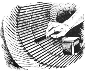
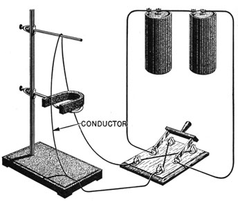
Figure 68.-Action of a conductor in a magnetic field.
The ACTION of a motor is based upon the old, familiar
law-UNLIKE POLES ATTRACT, and LIKE POLES REPEL.
To review the laws, look at figure 68. A conductor is
hung in a position that will permit it to swing freely
either in or out of the horse shoe magnet. Two dry cells
are connected to the wire through a double-pole, double-throw switch. The switch is so connected that by throwing the switch from one set of contacts to the other the
current through the conductor is reversed.
Closing the switch in one direction causes the CONDUCTOR
to move INTO the magnet. And throwing the switch
80
in the opposite direction causes the conductor to move
OUT.
The conductor's movement is caused by the COMBINED
ACTION of TWO MAGNETIC FIELDS-the field around the
conductor and the field of the horse shoe magnet.
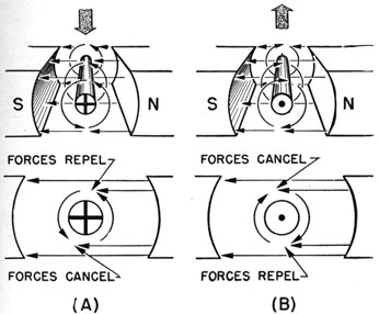
Figure 69.-Motor action.
In the bottom drawing of figure 69A, the conductor's
field and the flux of the field coil combine to CANCEL each
other at the BOTTOM and ADD to each other at the TOP.
This leaves a GREATER FORCE tending to move the conductor DOWN than up-and the conductor will move
DOWN.
In figure 69B, the current is flowing in the opposite
direction, and the effect of the field is reversed. The
two fields CANCEL ON TOP and ADD on the bottom, so the
conductor moves UP.
81
The action of a conductor in a magnetic field is known
by many different names, but the term "motor action" is
as good as any.
PARTS OF D.C. MOTOR
The essential parts of a d.c. motor are similar to those
of a generator. Look at figure 70. The four main parts
are-STATOR, ARMATURE, COMMUTATOR, and BRUSHES.
A battery attached to the brushes provides the energy
to drive the motor.
The differences between a d.c. motor and a generator
are usually only in the manner of mounting the brushes
and connecting the windings. Actually, some d.c. motors may be used as d.c. generators without any change
at all.
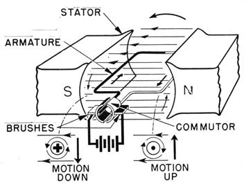
Figure 70.-Parts of an electric motor.
If you apply the MOTOR ACTION principle to the coil,
the WHITE leg in figure 70 will go UP, and the BLACK leg
will go DOWN.
When the loop has rotated 90° from its position in
figure 70, the brushes will "slip" from one commutator
82
segment to the other, and the direction of the current in
the loop will be reversed. The black leg will now move
UP and the white leg DOWN.
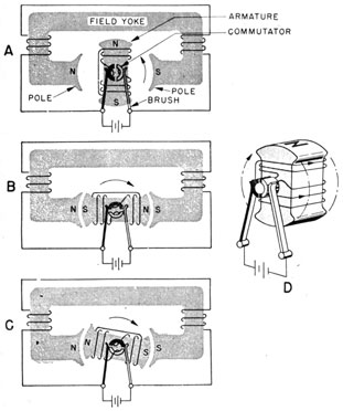
THE ST. LOUIS MOTOR
While the St. Louis motor does not have any commercial uses, it does demonstrate the operation of a d.c.
motor very well.
In figure 71 the STATOR (field yoke) is an electromagnet. The armature, figure 71D, is formed by winding
the coil on a soft iron core.
The COMMUTATOR is a two-segment, copper ring
mounted on the same shaft as the armature. Each segment
Figure 71.-St. Louis motor.
83
is insulated from the shaft so that no electrical
contact is made between armature core and commutator.
The BRUSHES are strips of copper.
To start a cycle of rotation, look at figure 71A. The
commutator is in a position to give the armature the indicated polarities. Since unlikes attract, and likes repel,
the armature will rotate in a CLOCKWISE direction.
When the armature reaches the position indicated in
figure 71B, N is opposite to S. This would cause the
armature to stop if it were not for the commutator. The
INERTIA of the armature carries the commutator far
enough for the black brush to move onto the white segment, and for the white brush to move onto the black
segment.
The "trading" of segments reverses the direction of
the current through the coil, and this in turn reverses
the polarity of the core. Now look at figure 71C-N is
opposite N, and S opposite S. The REPULSION between
the coil and armature fields causes the armature to continue turning.
When the armature assumes the vertical position of
figure 71, the repulsion is traded for attraction of the
opposite poles, and the cycle starts all over again.
While the d.c. motors used by the Navy are more
elaborate in their windings and construction, the basic
principle outlined here applies to the more complex types.
THE A.C. MOTOR
The a.c. motor is used more commonly than the d.c.
types. The reason for this is not in the motor, but in
the greater efficiency of using alternating current.
Some a.c. motors have WINDINGS, COMMUTATORS, and
BRUSHES similar to those of d.c. motors. In addition
a.c. motors have many variations. A few have armatures with no windings at all, just heavy bars of copper
embedded in soft iron cores. Other armatures have
windings but NO DIRECT electrical connection to the external source of power.
84
In many a.c. motors, it is INDUCTION that causes the
armature to turn. A current flowing in the field coil
causes a CURRENT to flow IN THE ARMATURE. The magnetic fields of these two currents oppose each other,
causing the armature to turn.
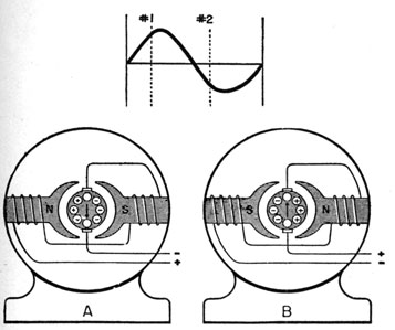
Figure 72.-Series a.c. motor.
One feature about the operation of an a.c. motor that
differs radically from d.c. types is due to PERIODIC reversal
of the current in a.c. circuits.
In figure 72A, when the TOP lead is NEGATIVE and the
BOTTOM POSITIVE, the left pole is North and right South.
In the armature, the current is flowing in at the left, and
OUT the right side.
In drawing 72B, the current has reversed itself (other
half cycle), making the top lead positive and the bottom
negative. The polarity of the field is reversed, and current in the armature is flowing in the opposite direction.
85
The REVERSING of the CURRENT in a.c. motors has the
same effect on the TURNING of the armature as the "trading" of segments in d.c. motors. It REVERSES the FIELDS
so that ATTRACTION and REPULSION will cause the armature to rotate.