Navy receivers are precision instruments, designed to
bring in messages under the most adverse conditions.
They are highly selective and sensitive, but careless, improper tuning can cause the set to lose half or more of
its efficiency. Therefore, it is necessary for you to learn
properly and practice diligently the tuning procedures.
After a short time the operation of receivers such as the
RBB or RBC will become nearly automatic.
The Navy receivers discussed in this chapter are not
the only types you will find on ships and shore stations,
but they are the sets you will find most frequently. Some
of the models will be used daily and others only occasionally for special purposes. Regardless of how much
or how often, you must learn how to tune all models on
your ship or station. You can expect to be called upon
to operate any set in an emergency.
The instructions in this chapter have been taken from
the manufacturers' instruction books. They are
307
summaries and will serve as a guide while learning. You should
obtain the manufacturers' instruction books at the earliest
opportunity and study them.
You can expect to find variations in the techniques of
tuning. Step 3 may become step 1, and step 5 omitted
entirely, but whatever the method or system used, be sure
you are getting the most out of your receiver.
The use of special controls designed to eliminate the
interference of noise and static is of considerable importance. A good operator, by intelligent use of these CONTROLS, can bring in a message clearly where a careless
and inefficient operator will have his signal completely
masked in noise.
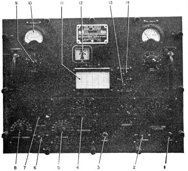
THE MODEL RAK/RAL RECEIVERS
The models RAK/RAL are companion receivers, usually installed in pairs. They are designed to cover two
Figure 171A.-The RAK receiver.
308
frequency ranges-15-600 kc. in 6 bands for the RAK,
and .3 -23 mc. in 9 bands for the RAL.
Both receivers are TRF, using two stages of tuned r.f.
amplification and a regenerative detector, followed by
two stages of audio amplification. Both have an output
limiter circuit.
The sets are designed for C.W. reception, but can be
used on I.C.W. or MOD.-C.W. The high selectivity, and
the low-pass filter in the audio section of the RAL, results in considerable distortion of VOICE reception.
The production of the BEAT NOTE for C.W. reception is
obtained by incorporating an AUTODYNE oscillator in the
regenerative detector circuit. Since this type of oscillator requires frequent adjustment, a REGENERATION CONTROL is mounted on the operating panel. For C.W. reception, the REGENERATION control is adjusted to produce
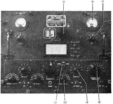
Figure 171B.-The RAL receiver.
309
oscillation; for I.C.W. and MOD.-C.W., the control is set
just below the point of oscillation.
The RAL receiver has a FREQUENCY VERNIER connected
into the autodyne circuit that permits variations in the
pitch of the audio beat note. This control is not a part
of the RAK equipment.
A LOW-PASS FILTER is included in both the RAK and
RAL circuits. This filter has three controls: OFF-ON, a
RANGE SWITCH, and a 10 point AUDIO TUNING dial. The
RANGE SWITCH selects one of two frequency bands, 450-770 or 770-1300 cycles. The TUNING DIAL selects the desired frequency within these ranges.
The original RAK and RAL receivers were designed
for d.c. operation. All subsequent modifications are designed for 110/120 volt, 60 cycle, single-phase, a.c., but
have provisions for emergency d.c. operation.
Modifications 1 through 5 are substantially the same
receiver. Modifications 6, 7, and 8 have increased protective shielding to prevent high frequency radar interference.
It is recommended that each RAK and RAL have a
separate antenna, but when it is necessary to operate
both from a common antenna, a loose input coupling must
be used.
1. OSCILLATOR TEST
This PUSH-BUTTON is used to determine whether the detector circuit is oscillating or not. When the button is depressed, a click is heard in the earphones. When released, another click is heard if the detector circuit is oscillating. No click, no oscillation.
2. BATTERY OPERATION
This switch is used when set is being OFF-ON SWITCH operated from batteries. It is shorted out of the circuit for a.c. operation.
3. PHONE JACK
Output of receiver for headset.
4. REGENERATION CONTROL
Controls the oscillation of the regenerative detector.
310
5. R.F. TRIMMER
Trimmer condenser in grid circuit of the 2nd r.f. stage. It is usually adjusted for maximum background noise at the high end of the dial each time the band is changed.
6. A.V.C. OFF-ON
Automatic volume control, off-on switch. Always OFF for modulated signal reception.
7. A.V.C. LEVEL
Sets the level of output volume when the a.v.c. switch is ON
8. ANTENNA TRIMMER
Used the same way as the R.F. TRIMMER. Located in grid circuit of first R.F. stage.
9. ADD DECIBELS
A five-position switch-OFF, 15, 10, 5, and 0. Used in connection with OUTPUT METER.
10. OUTPUT METER
Indicates the level of output volume.
11. CALIBRATION CHART
Record of dial settings for various frequencies.
12. CALIBRATED DIALS
Indicates position of main tuning control.
13. AUDIO TUNING BAND SWITCH
Selects one of two a.f. bands-450-770 or 770-1,300 cycles.
14. AUDIO TUNING, OFF-ON SWITCH
Cuts the audio filter IN or OUT.
15. MAIN TUNING CONTROL
The main r.f. tuning control. It tunes both r.f. stages, and the detector.
16. FILAMENT VOLTS
Indicates whether power is off or on. Should be about 6 volts.
17. AUDIO TUNING
A 10-position switch. It selects the desired a.f. beat note between 450-770 or 770-1,300 cycles, depending upon the setting of the AUDIO TUNING BAND SWITCH, 13.
18. FREQUENCY BAND SWITCH
Selects the desired frequency band. RAK, 6-positions; RAL, 9 positions.
19. SENSITIVITY
An r.f. control. Acts as a manual volume control.
20. FREQUENCY VERNIER
(RAL only.) Used to obtain small variations in the pitch of the a.f. beat note produced by the heterodyne oscillator.
21. AUDIO, BROAD-SHARP
(RAL only.) Connects a low pass filter into the circuit when in the SHARP
311
position. Removes the filter when in the BROAD position. Aids in reducing background noise with C.W. reception.
INSTRUCTIONS FOR OPERATION OF THE RAK-RAL
RECEIVERS
TUNING FOR C.W. SIGNALS
1. Turn on the power to the set you desire to operate.
If you wish to use both, turn on both sets. remember, if the installation is a double RAK/RAL
unit, the switches are on the CONTROL UNIT. If a
single set is installed, the switch is on the POWER
UNIT.
2. If the frequency of the station to be received is
known, set the following controls in the INDICATED
POSITION-
AUDIO TUNING
OFF
A. V. C.
OFF
AUDIO, BROAD-SHARP
BROAD (RAL only)
FREQUENCY VERNIER
ZERO (RAL only)
3. Set FREQUENCY BAND switch to the band number that includes the frequency of the station desired.
4. Refer to calibration chart and set tuning dial to the position indicated by the chart.
5. Advance sensitivity control until perceptible noise is obtained. Adjust ANTENNA TRIMMER, and R.F. TRIMMER for maximum noise output. Be careful
not to advance the SENSITIVITY CONTROL too far,
because too much noise will MASK the signal.
6. Increase REGENERATION control until a double
CLICK is heard when the O.S.C. TEST button is
pressed and released indicating the director is
oscillating.
7. Reset TUNING control until desired signal is heard,
then adjust ANTENNA TRIMMER and R.F. TRIMMER
until maximum signal is obtained.
8. On RAL only. Adjust FREQUENCY VERNIER control
until the desired beat note is heard.
312
9. Turn up SENSITIVITY control until a perceptible
noise level is present, but not in excess of 10 DB.
Throw A.V.C. switch ON, and adjust A.V.C. LEVEL
until a copyable signal is obtained.
10. Place AUDIO TUNING switch ON. Select the desired
AUDIO RANGE, 450-770 or 770-1,300. Adjust AUDIO
TUNING to the selected audio signal frequency.
With the RAL, the FREQUENCY VERNIER may be
used for the final adjustment.
TUNING FOR M.C.W. VOICE SIGNALS
1. Procedure is the same as outlined for C.W. reception, except that the REGENERATION control should
be adjusted to a point just below oscillation.
2. To adjust the REGENERATION control properly for
and MOD.-C.W., increase the REGENERATION
control until a click is just heard when the O.S.C.
TEST button is pressed. Now retard the REGENERATION control until the click does not appear when
you press the test button. The regenerative CONTROL is set just below the point where the set will
break into oscillation.
3. The RAK/RAL receivers are not expressly designed for voice or other modulated C.W. reception.
With the RAL, the low-pass filter cuts off all audio
signals above 1,200 cycles, and this results in considerable distortion.
THE RAO-RBH RADIO RECEIVERS
The RAO-RBH radio receivers are very similar in panel
design and tuning control arrangement. Electrically, the
two receivers have variations in component parts and circuit design to accommodate differences in frequency
bands. But the tuning and operating procedures for the
two are nearly the same.
The RAO has a frequency range from 540 to 30,000
kcs. in five bands, and the RBH has a frequency range
from 300 to 1,200 and 1,700 to 16,000 kcs., also in five
699198°-46-21
313
bands. Both receivers may be used for C.W.-M.C.W. or
VOICE reception.
Superheterodyne circuits are used in each receiver.
They contain a beat frequency oscillation for C.W. reception and a crystal filter in the intermediate frequency
stages to eliminate interfering signals when the sets are
operating on C.W. The crystal filter circuit is usually
turned off for VOICE reception, because the extreme selectivity when the crystal filter is ON will not permit intelligible voice signals to come through.
Provisions are made for headset and loudspeaker outputs. The headset jack is on the front of the operating
panel, while two speaker outlets are on the back of the
cabinet. The receiver is designed to use a Navy Type
CNA-49106 loudspeaker.
Do not place the loudspeaker on the top of the receiver
cabinet, because speaker vibrations may cause microphonic noises in the form of "mechanical feed-back" to
distort the receiver's signals.
Since the RAO receiver tunes over the broadcast band,
and is also adaptable for use with a loudspeaker, it is
often used for program entertainment.
The receivers have their own built-in power supplies,
and can be operated from any 115/120 volt, 50/60 cycle
single-phase line supply.
The antenna length used with either receiver is not
critical. A single wire varying in length from 50 to 20
feet is satisfactory. A low-impedance transmission line
of not less than 70 ohms may be used to connect the
antenna to the receiver.
1. SIGNAL STRENGTH METER
Shows the signal strength in the last I.F. stage
2. POWER SUPPLY, OFF-ON
This switch turns the receiver on and off.
3. METER SWITCH STRENGTH
Closing this switch puts the SIGNAL meter into operation.
314
Figure 172.-The RBH Receiver. (Front view).
4. LIMITER CONTROL
This control limits the maximum signal strength to come through the receiver. When set on 0, all but the strongest signals come through. When set on 10, only the very weakest can get through.
5. CONTROL SWITCH A.V.C.-M.V.C.-C.W.O.
In A.V.C. position, the automatic volume control circuits are operating. In M.V.C. position, the automatic volume control circuits are off. In C.W.O., the B.F.O. is turned on and the A.V.C. off.
6. TONE CONTROL
In the N position all normal audio tones come through. When in HIGH position, all frequencies below 100 cycles are cut off. Low position cuts off all frequencies above 1,000 cycles.
7. PHONE JACK
Output jack for headset.
8. MAIN TUNING KNOB
This knob tunes the receiver.
9. BAND CHANGING SWITCH
This knob switches the receiver from one frequency band to another.
10. R.F. GAIN CONTROL
This gain control manually regulates the gain of the first r.f. stage.
11. A.F. GAIN CONTROL
Manual volume control.
315
12. PHASING CONTROL
In the OFF position, the crystal filter is out of the circuit. Increasing the setting of the control from OFF to O connects the filter into the circuit. Increasing the control from O balances the crystal bridge circuit to eliminate undesirable beat notes. This control determines the pitch of the C.W. beat note.
13. C.W. O.S.C. CONTROL
The degree of selectivity for the crystal filter is regulated by this control.
14. SELECTIVITY CONTROL
The degree of selectivity for the crystal filter is regulated by this control.
15. MAIN CALIBRATION
Shows the setting of the tuning control.
OPERATION OF THE RAO-RBH RECEIVER
M.C.W. OR VOICE RECEPTION
1. Set the following controls in the indicated
positions:
CONTROL
POSITION
POWER SUPPLY
ON
LIMITER
0
TONE
N
R.F. GAIN
8 to 10
A.F. GAIN
4 to 6
PHASING
OFF
SELECTIVITY
MAX. NOISE
CONTROL SWITCH
A.V.C. or M.V.C.
2. Turn the BAND CHANGING switch to the correct
band, and set the MAIN TUNING knob in the position indicated on calibration card for receiving
the desired frequency.
3. When the control switch is set for M.V.C. operation, be careful not to advance the R.F. GAIN CONTROL to a point where signal distortion occurs. In
general, it is recommended that the A.F. GAIN
control be set about half way on, and audio output
adjusted by means of the R.F. GAIN control.
316
4. With the CONTROL switch in A.V.C. position, the
R.F. GAIN control should be advanced as far as receiving conditions permit, or until background noise
becomes objectionably loud. Audio output should
be adjusted entirely by means of the A.F. GAIN
control. Remember, the automatic gain control is
not effective unless R.F. GAIN is fully advanced.
5. If a signal is weak and partially obscured by background noise and static, best signal-to-noise ratio
will be obtained by turning the TONE towards the
LOW position. The most effective setting must be
determined by trial.
6. When a signal is accompanied by crashes of static,
advance the LIMITER control towards 10. Best setting must be determined by trial. Too much limiter action will impair the audio quality. If static
peaks are extremely strong, best LIMITER action is
obtained with the CONTROL switch in M.V.C. position . In such cases, both R.F. GAIN and LIMITER
controls must be carefully adjusted for optimum
operation.
7. After tuning has been completed, switch crystal
filter on by setting the PHASING control at any position greater than 0. For M.C.W. operation, a
normal setting is 5.
8. The normal setting of the SELECTIVITY control for
M.C.W. reception is at the position that affords
minimum SELECTIVITY. This position is near the
middle of the selectivity scale and is accurately determined by the point where the background noise
is maximum.
9. The PHASING control is used to eliminate interfering beat notes that are often present when
crystal filter is "in." If the note is above 1,000
cycles, set the control near the mid-point of the
dial. If the note is near 300 to 400 cycles, optimum
setting is near either end of the dial.
10. For M.C.W. reception, set the tone control in HIGH
position. VOICE communication that is
317
accompanied by serious background noise can sometimes
be improved by setting the TONE control in Low
position.
C.W. OPERATION
1. The initial adjustments of the RAO-RBH for C.W.
operation are the same as for M.C.W. or VOICE,
except that the CONTROL switch must be in C.W.O.
position, and the C.W.O. O.S.C. control must be
set at mid-scale.
2. The. action of the TONE and LIMITER CONTROLS are
the same as for M.C.W., except that both controls
may be advanced considerably more.
3. Adjust the C.W. O.S.C. control until you obtain the
beat note of the desired pitch.
4. Increase the setting of the PHASING control, and
increase the SELECTIVITY by moving the control toward 0. For best operation it will be necessary to
try several combinations of these controls.
THE RBA RECEIVER
The model RBA radio receiver is a low frequency T.R.F.
receiver designed for VOICE, C.W., and M.C.W. reception.
The frequency range is from 15 to 600 kc., in four bands,
15-38, 38-95, 95-235, and 235-600 kc.
While voice reception is possible, many natural characteristics are lost due to the high selectivity and the
filters employed in the r.f. stages. When attempting to
receive a voice message, the AUDIO switch, NO. 10, should
be in the BROAD position. For C.W. reception it should be
set for SHARP reception.
A beat-frequency heterodyne OSCILLATOR is incorporated into the circuit for C.W. reception. The oscillator is ganged to the MAIN TUNING CONTROL, 13, and is automatically tuned to the correct frequency to produce a
beat note of 1,000 cycles for each setting of the r.f. stages.
The selection of the FREQUENCY BAND is accomplished
by rotating a four-position switch. All r.f. and oscillator
coils are changed by the movement of this switch.
318
TUNING is accomplished by a panel-operated, 5-gang,
variable condenser which tunes the input, r.f. amplifier,
and B.F.O. circuits. The setting of the tuning control is
indicated by the MAIN DIAL, 5, and the VERNIER DIAL above
the main tuning control. The top scale of the main dial
has arbitrary numbers such as 0, 50, 100, 150, and 1,000.
The vernier dial has 100 equal divisions. The lower scale
of the main dial is calibrated approximately in kilocycles.
The MANUAL GAIN CONTROL regulates the gain in the
r.f. and a.f. stages. An additional gain control is geared
to the main tuning control, so that as the receiver is tuned
toward the high end of the band, the volume is reduced.
This arrangement insures a uniform output over the
entire tuning range.
An OUTPUT LIMITER is used in the circuit to prevent
sudden crashes of static from reaching the earphones.
The automatic regulation of the receiver's output
volume is a unique feature of this set, because it permits
the use of any number of headphones between 1 and 20
without material loss in the output volume.
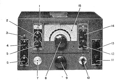
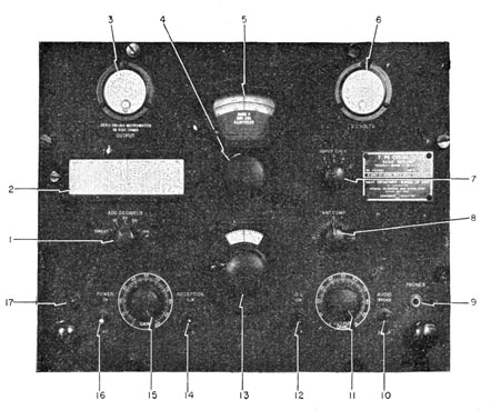
Legend for Figure 173.
1. ADD DECIBEL
The ADD DECIBEL SWITCH and the OUTPUT METER work together.
2. CALIBRATION CHART
Indicates the proper dial settings for various frequencies the receiver may be tuned to.
3. OUTPUT METER
WHEN NOT USING THE OUTPUT METER, BE SURE SWITCH IS IN OFF POSITION TO PREVENT DAMAGE TO THE METER.
4. BAND SELECTOR SWITCH
A four-position switch that selects the frequency band.
5. MAIN TUNING SCALE
Indicates the setting of the main tuning control. To obtain readings of dial settings, add the readings of the vernier dial to the next smaller reading in 100's on the main dial. Example: vernier 56, main dial between 300 and 400. Actual reading 300 + 56 = 356.
319
Figure 173.-The RBA receiver.
6. D.C. VOLTS
Indicates the voltage applied to the plate circuits of the amplifier tubes. Normal is 240 volts; may be between 175 and 225.
7. INPUT COUPLING
A five-position switch that adjusts the degree of coupling between the antenna and first r.f. stage. Correct coupling produces loudest signal.
8. ANTENNA COMPENSATOR
A small variable condenser used to compensate for variations in antenna lengths. Correct adjustment gives loudest signal.
9. PHONES
Jack for headset output.
320
10. AUDIO, BROAD-SHARP SWITCH
Used to reduce side noise interference. For VOICE communication, set switch to BROAD; for C.W., to SHARP.
11. OUTPUT LEVEL
This control works with the OUTPUT LIMITER. It sets the maximum level to which the sound is permitted to rise.
12. O.L. ON-OFF
The OUTPUT LIMITER switch. Should be OFF while completing the fine tuning adjustments, and ON when operating. When searching for stations, or receiver in stand-by, the switch should be ON.
13. MAIN TUNING KNOB
This control tunes the receiver scale. Directly above the knob is the VERNIER DIAL.
14. RECEPTION, MOD.-C.W.
Switch. For VOICE and M.C.W., turn to MOD. For C.W. messages, set to C.W.
15. GAIN
Manual volume control of recliner.
16. POWER, OFF-ON
Switch for turning the set ON or OFF.
17. POWER, OFF-ON PILOT LIGHT
Indicates application of power to equipment.
INSTRUCTIONS FOR OPERATING THE RBA RECEIVER
TUNING FOR C.W. OPERATION
1. Set the following controls in the indicated position:
CONTROL
POSITION
INPUT CPLG.
5
ANT. COMP.
0
ADD DECIBELS
OFF
AUDIO, BROAD-SHARP
BROAD
OUTPUT LEVER
60-80
O. L.
OFF
RECEPTION
C.W.
GAIN
60-80
POWER
ON
2. Turn BAND SWITCH to the desired frequency band.
3. Turn MAIN TUNING dial to a signal near the high
frequency end of the band. If no signal can be
found near this setting, turn the MAIN TUNING dial
to a point of maximum noise.
321
4. Reduce the audio output to a low level by turning
the OUTPUT LEVEL control counterclockwise.
5. Adjust ANT. COMP. to resonance as indicated by a
maximum signal. The signal strength at this point
should drop off sharply at each side of this resonant
point. If this point cannot be found, move (ANT.)
CPLG. control to position 4 and then successively to
3, 2, and 1, if necessary, to resonate the antenna
circuit. The normal setting of this control with
most antennas will be 4 or 5. After one tuning
adjustment on a fixed antenna has been made,
further adjustments are usually unnecessary.
6. Adjust MAIN TUNING dial until a maximum signal
is heard in the headset, or indicated on OUTPUT
meter. To activate the OUTPUT meter turn ADD
DECIBELS SWITCH to 30. If a readable deflection is
not obtained with the 30 setting, move the switch
successively to 20, 10, or DIRECT as is necessary to
obtain a good reading, but no further.
7. Set OUTPUT LEVEL control to a point where the audio
volume is of the desired level. If a strong signal
causes distortion in the audio signal, reduce the
setting of the GAIN control, and then readjust OUTPUT LEVEL to the desired volume.
8. If crashes of static are objectionably strong, throw
O. L. switch to ON position.
9. When interfering tones appear with the C.W. beat
note, move the AUDIO switch to SHARP. This will
cut out practically all but the 1,000 cycle beat note.
TUNING FOR M.C.W. AND VOICE RECEPTION
1. Set all controls as listed in paragraph 1 for C.W.
tuning, except RECEPTION switch, which should be
set on MOD.
2. Repeat all other tuning steps, 2 through 8. If the
output limiter circuit interferes with intelligible
reception of audio signals, place the 0. L. switch in
the OFF position.
322
THE RBB-RBC RADIO RECEIVING SETS
The RBB-RBC radio receiving sets are companion
receivers designed to cover a frequency range of 0.5 to
4.0 mc for the RBB and 4.0 to 27.0 mc. for the RBC.
Many sections of the two receivers are identical and can
be interchanged. The chief variations are in the component parts of the tuned radio frequency stages.
The sets are usually installed in pairs, giving a complete frequency coverage from 0.5 to 27 mc. Signals of
C. W., M.C.W., and VOICE may be received by either.
POWER SUPPLIES are separate from receivers, and can
be installed behind, to the side of, or below the receiver
cabinets in the space available. They may be operated
from 110/120 volt, 60-cycle, single-phase power lines.
The OUTPUT CIRCUITS are designed to accommodate
from one to twenty pairs of 600-ohm headsets with only a
slight reduction in volume. This feature makes it possible to use these receivers to feed several remote radio-phone stations about the ship.
Both sets contain several auxiliary circuits to aid you
in receiving code and voice communications under adverse operating conditions. The OUTPUT LIMITER circuit
prevents strong crashes of static from reaching the headset. The SILENCER CIRCUIT blocks the receiver and keeps
background noise at a minimum when the receiver is in
stand-by condition.
The AUDIO SELECTIVITY FILTER, used only with C.W. reception, limits the audio output sharply to a 1,000 cycle
beat note, thus further reducing the extraneous noises.
Both receivers may be operated from a single antenna.
but when this is done, a link coupling inside each receiver cabinet must be opened to insert a decoupling
resistor in the antenna circuit. This prevents one receiver from interfering with the operation of the other.
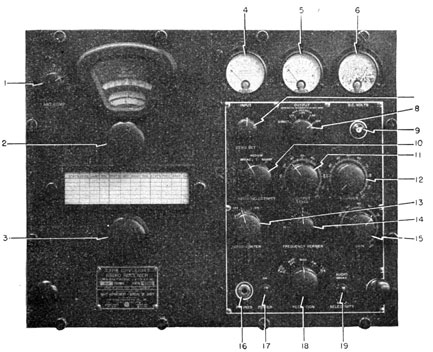
Legend for Figure 174.
1. ANT. COMP. CONTROL
This control is used to compensate for variations in the capacity of the various antenna circuits.
323
Figure 174.-The RBB/RBC: receiver. (Front View)
2. FREQUENCY BAND SWITCH
This control selects the frequency bands.
3. MAIN TUNING KNOB
The receiver is tuned by this control.
4. INPUT METER
Indicates the strength of the input signal at the 1st I.F amplifier stage.
5. OUTPUT METER
Indicates the strength of the audio frequency signal.
6. D.C. VOLTS METER
This meter shows the D.C. voltage applied to the a.f. amplifier tubes.
7. ZERO SET
This control is used to set the INPUT meter at zero.
324
8. ADD DECIBELS SWITCH
This switch is used to turn the output meter on and to set its RANGE of the meter readings.
9. PILOT LIGHT
Indicates whether set is turned ON or OFF.
10. RADIO SELECTIVITY SWITCH
This switch sets the degree of selectivity for the receiver.
11. OUTPUT LEVEL CONTROL
A manual audio volume control.
12. SILENCER CONTROL
The setting of this control determines the degree of silencing action.
13. NOISE LIMITER CONTROL
This control turns the noise limiter circuit ON or OFF.
14. FREQUENCY VERNIER CONTROL
This control adjusts the pitch of the C.W. beat note.
15. GAIN CONTROL
Manually regulates the gain of the R.F. and I.F. amplifier sections of the receiver.
16. PHONE JACK
Phone jack for headset.
17. POWER, ON-OFF SWITCH
This switch turns the set ON or OFF.
18. RECEPTION SWITCH
This switch selects the mode of reception for the receiver such as M.C.W., C.W. or VOICE.
19. AUDIO SELECTIVITY
A two-position Switch, BROAD and SHARP. In the SHARP position, an audio filter is inserted in the circuit to eliminate all audio signals except a 1,000 cycle note.
USE OF SPECIAL CONTROLS
ANTENNA COMPENSATOR:
When you have changed frequency bands, a signal
should be tuned in near the high frequency end of the
band. The ANTENNA COMPENSATOR should then be
adjusted for a maximum signal strength.
ZERO SET:
The INPUT meter is set to "0" with the ZERO SET
control-tune the receiver to a minimum signal at some
point NEAR the location of the signal, and then adjust
the ZERO SET until the INPUT meter indicates "0."
325
ADD DECIBELS:
The normal position of this switch while operating is
OFF. When you desire an OUTPUT meter reading, turn
the ADD DECIBELS switch first to 30. Advance the switch
to 20, 10, and DIRECT only when you are sure the signal
will not overload and injure the meter.
RADIO SELECTIVITY:
The initial tuning of the receiver is usually done with
switch in BROAD position, and then advanced to MEDIUM
and SHARP for the final adjustments in tuning. For
VOICE reception, this switch may require a MEDIUM or
BROAD setting. Attempts to perform initial tuning with
the RADIO SELECTIVITY control in SHARP position may
cause you to pass over a signal.
SILENCER:
The silencer circuits reduce the receiver's audio output
to zero when no signal is being received. Advance the
SILENCER control just enough to keep down set and
background noises when the receiver is in stand-by
condition, but not so far as to BLOCK the signal. The
SILENCER control is operative only when the RECEPTION
switch is in MOD.-A.V.C.-SIL. position.
RECEPTION SWITCH:
MOD.-A.V.C.-SIL.: This position is used principally
when the receiver is in stand-by condition on voice
communications. Do not attempt to tune set when
the control is set in this position unless SILENCER CONTROL is set at zero.
MOD.-A.V.C.: This is the normal operating setting for
VOICE and M.C.W. signals. May be left in this position
during the tuning of the set for VOICE and M.C.W.
signals.
MOD: This setting may be used for reception of VOICE
and M.C.W. signals when fading is not serious. This
setting is recommended for tuning, especially for inexperienced operators.
326
C.W.: The B.F.O. is connected into the circuit. Recommended position for tuning in C.W. signals. This
setting may be used for operating when crashes of
static and fading are at a minimum.
C.W.-O.L.: Normal operating setting for the reception of C.W. signals. The OUTPUT LIMITER'S effects,
on this mode of reception, is similar to A.V.C. action.
With this setting, the INPUT meter is inoperative.
Operate NOISE LIMITER AND AUDIO SELECTIVITY With the
FREQUENCY VERNIER until the best copyable signal is
received.
AUDIO SELECTIVITY:
When objectionable background noises interfere with
receiving C.W. signals, set this control on SHARP. adjust FREQUENCY VERNIER until the 1,000 cycle note is
obtained.
TUNING PROCEDURE FOR C.W. OPERATION
1. Set the following controls in the indicated position:
CONTROL
POSITION
POWER
ON
RECEPTION
C.W.
AUDIO SELECTIVITY
BROAD
NOISE LIMITER
OFF
FREQUENCY VERNIER
0
GAIN
60-90
RADIO SELECTIVITY
BROAD
OUTPUT LEVEL
60-90
ADD DECIBELS
OFF
SILENCER
0
2. Tune in a signal, or set TUNING dial to a position
of maximum noise near the high frequency end of
the band you have selected. Adjust ANT. COMP.
for a maximum signal as indicated by the OUTPUT
meter or sound in the headset. Further adjustment of the ANT. COMP. is unnecessary as long as
you operate on the one frequency band. Changing
frequency bands requires further adjustment.
327
3. Turn MAIN TUNING dial to a point of minimum
noise NEAR the desired signal. Adjust ZERO SET
until the INPUT meter needle is at ZERO.
4. Tune in desired station. The correct setting of the
tuning dial will be indicated by a maximum deflection of the INPUT meter needle.
5. Set RADIO SELECTIVITY Switch successively to MEDIUM and SHARP, and make final tuning adjustments until a maximum indication is obtained on
the INPUT meter.
6. Adjust OUTPUT LEVEL, and operate ADD DECIBEL
switch until the desired output volume of sound
is obtained.
7. Turn NOISE LIMITER to ON, RECEPTION switch to
C.W.-O.L., and FREQUENCY VERNIER to "0."
8. If considerable noise is present with the C.W.
beat-notes, place the AUDIO SELECTIVITY switch in
SHARP position. Make slight adjustments of the
FREQUENCY VERNIER until a pure beat note is obtained. When the AUDIO SELECTIVITY switch is in
BROAD position, the pitch of the beat note may be
varied by the FREQUENCY VERNIER.
9. Make final adjustments of GAIN control if an extremely strong signal is causing distortion. Set
the OUTPUT LEVEL control to a position that produces the desired audio level.
TUNING PROCEDURE FOR M.C.W. AND VOICE RECEPTION
1. Set all controls as listed in paragraph 1 of C.W.
tuning instructions, except RECEPTION, which should
be set at MOD.
2. Perform all tuning steps, 2 through 6, as listed for
C.W. operation.
3. Turn RECEPTION switch to MOD.-A.V.C., and adjust OUTPUT LEVEL until the desired level of volume
is obtained.
4. When conditions require stand-by VOICE operation,
turn RECEPTION switch to MOD.-A.V.C.-SIL., and
adjust SILENCER control until you obtain the
328
desired degree of damping on background noise. Do
not advance SILENCER control too far. It may cut
out part of the signal.
THE RBK RECEIVER
The Navy model RBK receiver is a very high frequency
receiver capable of receiving amplitude and frequency
modulated signals within a frequency range of 27.8 to 143
megacycles.
The circuit is that of a conventional superheterodyne
with one stage of tuned radio frequency preceding the
first detector.
To change from the reception of amplitude modulated
to frequency modulated signals, you merely turn a switch
on the operating panel of the receiver. A single audio
frequency amplifier is used for both the A.M. and F.M.
sections of the receiver.
Figure 175.-The RBK receiver. (Front view).
The frequency range of the receiver, and the fact that
it is capable of receiving both A.M. and F.M. signals
makes this set valuable for short range, such as communication between aircraft and ground forces employing
frequency modulated transmitters.
699198°-46-22
329
Reception by C.W., M.C.W., or VOICE is possible with
this receiver. When it is necessary to locate a weak
signal, the beat frequency oscillator may be switched on
to increase the sensitivity of the set.
When the RBK is being operated in an area free from
local interference, a single wire about 75 feet long is
recommended. Where reception is subjected to strong
local interference, and the frequency band of reception
is narrow, a dipole antenna of the doubler type is best.
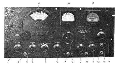
Legend for Figure 175.
1. R.F. GAIN CONTROL
This control adjusts the sensitivity of the r.f. amplifier sections.
2. A.V.C. OFF-ON SWITCH
Turns A.V.C. circuits ON or OFF.
3. BAND SWITCH
This switch selects one of the receiver's three frequency bands.
4. ANTENNA TRIMMER
The ANTENNA trimmer is a small variable condenser in the input to the first r.f. stage used to compensate for variations in the antenna capacity.
5. SELECTIVITY SWITCH
This switch controls the selectivity of the I.F. amplifier stages.
6. A.F. GAIN CONTROL
A manual volume control.
7. A.N.L. ON-OFF SWITCH
This switch is used to eliminate local electrical interference that may originate with ignition systems and the like.
8. TUNING DIAL
This is the receiver's main tuning dials.
9. A.M.-F.M. SWITCH
This switch designates whether the set is to receive A.M. or F.M. signals.
10. B.F.O. SWITCH
This control turns the B.F.O. ON or OFF.
11. PITCH CONTROL
Adjusting this control sets the pitch of the beat note when receiving C.W. signals.
12. PHONE JACK
Output jack for the headset.
13. SEND-RECEIVE
When this switch is in the SEND position, the receiver is in stand-by condition. The filaments of the tubes remain heated, but the plate voltages are off. Placing this switch in RECEIVE position energizes all of the circuits.
330
14. TONE CONTROL
This control is used to regulate the pitch of the audio tone. This is especially useful for VOICE reception. Proper adjustment of this control can be used to eliminate objectionable background noises.
15. TUNING METER
This meter indicates the strength of the signal applied to the second detectors. It is useful in tuning the receiver, since it will indicate the presence of a signal even if its strength is too weak to be heard.
16. VERNIER SCALE 17. MAIN CALIBRATED SCALE
Scales 16 and 17 together indicate the settings of the TUNING dial.
OPERATION OF THE RBK RECEIVER
TUNING FOR C.W. OPERATION
1. Set the following controls in the indicated position:
CONTROL
POSITION
R.F. GAIN
7 TO 9
A.V.C.
ON
BAND SWITCH
TO DESIRED BAND
SELECTIVITY
BROAD
A.F. GAIN
5 OR 6
A.N.L.
OFF
PITCH CONTROL
0
SEND-RECEIVER
RECEIVE
TONE
NORMAL
2. Place the A.M.-F.M. switch in A.M. position to receive the type of modulation being transmitted.
3. Operate the TUNING wheel, and set MAIN CALIBRATED scale to approximately the correct position
for receiving the desired signal.
4. Adjust ANTENNA control and at the same time readjust the TUNING wheel slightly, until a maximum
signal is heard or indicated on the TUNING meter.
5. Adjust the A.F. GAIN for desired volume. Reduce
331
R.F. GAIN as necessary to eliminate signal distortion.
6. When interfering signals make it necessary, turn
SELECTIVITY control to SHARP. Adjust PITCH CONTROL until you obtain the beat note of the desired
pitch.
7. Make final adjustments of tuning, gain, pitch, and
tone controls until the best copyable signal is
obtained.
TUNING FOR M.C.W. AND VOICE RECEPTION
1. Tuning is the same as for C.W. reception, except
for the following points-the B.F.O. is OFF, the
SELECTIVITY control is usually left in the BROAD
position, and the A.M.-F.M. switch is turned to
the position to receive the type of modulation being transmitted.
2. Set the TONE control and other tuning signals.
The A.V.C. switch must be ON and the R.F. GAIN
set at maximum gain.
USE OF THE TUNING METER
1. When using the TUNING meter with A.M. signals,
the A.V.C. switch must be ON and the R.F. GAIN
set at maximum gain.
2. While using the TUNING meter with F.M. signals,
the meter needle will be deflected to one side of
zero as you approach the carrier frequency, and to
the other side when the carrier is passed. When
the receiver is correctly tuned, the meter needle
will stand near ZERO.
THE MODEL RCK RADIO RECEIVER
The model RCK radio receiver is one of the newer high
frequency types to be introduced to the Navy. It operates in the V.H.F. band between 115 and 156 mc.
This receiver is designed to be used with the TDQ transmitter for short range, line-of-sight, voice communication between ship and aircraft, and between ship to ship.
332
The receiver itself is a superheterodyne, with a single
r.f. preselector stage, followed by a mixer and five I.F.
amplifier stages. The second detector is of the diode
type. Three stages of audio amplification follow the
detector. The audio section also contains a circuit that
can be set from the control panel to the desired level of
CRASH suppression.
The TUNING of the receiver is limited to four predetermined channels to match the four frequencies of the
TDQ transmitter. The frequency of each channel is CONTROLLED by one of the four crystals in the local oscillator
stage. The frequencies of these channels can be changed
to any other within the band range merely by switching
crystals in the receiver to match the change of crystals
in the TDQ.
This receiver has fewer controls and is easier to operate than many Navy types. It is designed to supply a
single set of headphones, and by using a suitable amplifier, it may feed remote stations about the ship.
The ANTENNA used with this receiver is a fixed dipole,
connected to the receiver by a 50-ohm coaxial transmission line. The maximum length of the transmission line
shall not be over 100 feet, and it is recommended that
it be as short as possible.
The POWER SUPPLY is built into the same cabinet as
the receiver, and may be operated from any 110/120 volt,
55/60 cycle, single-phase power source. The power consumption is about 110 volts, and the set is protected by
two 3-ampere fuses.
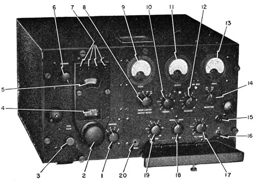
Legend for Figure 176.
1. CHANNEL SWITCH
Connects the crystals into the oscillator circuits to match the TDQ frequency.
2. TUNING CONTROL
Tunes the r.f. and local oscillator circuits.
3. DIAL LOCK
Locks the tuning dial in the desired position. To release, turn counterclockwise.
4. LINEAR DIAL SCALE
Indicates the TUNING CONTROL settings.
5. DIAL SCALE IN M.C.
Indicates the frequency in megacycles to which the receiver is tuned.
699198°-46-23
333
Figure 176.-The RCK receiver.
6. DIMMER
Controls the brilliancy of the channel indicator lights.
7. CHANNEL LIGHTS
Indicates the frequency channel to which the receiver is tuned.
334
8. NOISE LIMITER OUTPUT METER
A four-position switch.-Noise limiter, N.L.-Output meter, O.M.-both N.L. and O.M. at once.
9. PLATE VOLTAGE METER
Shows the value of voltage on the plate of the second a.f. amplifier tube.
10. PHONE
Controls the output level of sound delivered to the phones.
11. OUTPUT METER
Shows the output level of sound delivered to the headphones.
12. SILENCER
Adjusts the level of the permissible noise when no signal is being received.
13. INPUT METER
Shows the amount of plate current flowing in the third I.F. amplifier stage.
14. RECEPTION
A.V.C. ON-OFF switch. When OFF, the output meter and silencer are also out of the circuit.
15. PILOT LIGHT
Indicates application of power to receiver.
16. OFF-ON SWITCH
Applies power to equipment.
17. R.F. GAIN CONTROL
Controls the sensitivity of the r.f. amplifiers and 1st, 2nd, 3rd, and 5th I.F. amplifiers.
18. A.F. BAND
The switch that cuts in and out of a filter in the a.f. amplifier. When noise is bad turn to NARROW.
19. A.F. GAIN CONTROL
A manual audio volume control.
20. PHONES
Headphone output.
INSTRUCTIONS FOR OPERATION OF THE RCK RECEIVER
TUNING FOR M.C.W. AND VOICE OPERATION.
1. Set the following controls in the indicated position:
CONTROL
POSITION
ON-OFF
ON
R.F. GAIN
8
A.F. BAND
BROAD
A.F. GAIN
8
NOISE LIMITER- OUTPUT METER
OFF
PHONES
8
335
CONTROL
POSITION
SILENCER
0
RECEPTION
A.V.C.-ON
2. Release DIAL LOCK and set CHANNEL switch to the
desired channel.
3. Refer to calibration card and adjust dial until a
maximum indication is obtained on the INPUT
meter.
4. Turn NOISE LIMITER-OUTPUT METER switch to O.M.
Adjust A.F. GAIN, until the audio output of the
receiver is at the desired level as indicated by the
OUTPUT meter.
5. If the signal received is very strong, and is causing
considerable distortion, reduce the R.F. GAIN CONTROL until an undistorted signal is obtained. Readjust A.F. GAIN for desired audio output.
6. The final setting of the NOISE-LIMITER-OUTPUT
METER switch will depend upon the character of the
reception Usually it will be set at N.L. For
normal operation, it is not advisable to have switch
in either O.M. or N.L.-O.M. positions. Turn on
output meter only when actually adjusting or
checking set.
7. Increase setting of SILENCER control to a point
where silent operation is obtained when the receiver is in stand-by condition. Do not increase
setting of the SILENCER control so much that it
cuts off the first part of the incoming message.
Too much silencer action will also block weak
signals.
8. The setting of the PHONE control will be according
to instructions from the operators at remote radiophone stations. Usually this control will be near
maximum, because the earphone level can be reduced at the remote stations also.
9. The A.F. BAND switch is used when you are receiving M.C.W. messages. In the NARROW
336
position, a band-pass filter is inserted in the audio
circuit, and limits the audio signal sharply to the
pitch of the M.C.W. note. Place this control in the
NARROW position when set and background noises
interfere with the reception of the M.C.W. signals.
337
How Well Do You Know-
INTRODUCTION TO RADIO EQUIPMENT
339
QUIZ CHAPTER 1 WHAT IS ELECTRICITY?
1. All atoms are composed of _____ and _____.
2. An object becomes positively charged by______and NEGATIVELY charged by______
3. The law of charges states______
4. What is a static charge?
5. What will happen if a copper wire is connected between two static charges?
6. Electrons in motion is the definition of______
7. A coulomb per second is equivalent to an______
8. A volt is the expression of______
9. A. Arrange the following potentials in order from most NEGATIVE to highest positive: -, 75, -135, -2, 425, 0.
B. What is the magnitude of the potential difference between the highest and lowest value?
10. The opposition of a conductor to the flow of current is______
11. Select the materials from the following list that are considered insulators: Mica, carbon, bakelite, zinc, dry air.
12. Name three types of resistors commonly used in radio circuits.
CHAPTER 2 BATTERIES
1. Any force that tends to keep electrons moving is______
2. What materials are necessary to form a cell?
3. Copper and lead are used to make a cell. Which pole will be positive?
4. The______action within a cell is responsible for causing the current to flow.
5. The dry cell is an example of a______cell, and the storage cell is an example of a______cell.
6. Secondary cells can be, while primary cells cannot.
7. The degree of charge of a storage cell is checked with a______
8. Cells connected in either series or parallel are called______
9. Connecting cells in series increases the______, while
connecting cells in parallel increases the available______
341
CHAPTER 3 CIRCUITS
1. An electrical circuit requires a______for the electrons to follow.
2. In a series circuit, the same current______, of the circuit, while in parallel circuit, the current______with the larger portion flowing through the ______ resistance.
3. What is the resistance of a series circuit that contains the following resistors: 100 ohms, 200 ohms, 300 ohms. If the three
resistors are in parallel?
CHAPTER 4 OHM'S LAW
1. State Ohm's Law?
2. A circuit has an emf of 100, and a resistance of 20,000 ohms.
What is the current? What is it when expressed in milliamperes?
3. The IR drops about a series circuit are 18 volts, 22 volts, 112
volts, and 84 volts, what is the applied emf?
4. A potential of 2,000 volts is being applied to the vacuum tubes
of a transmitter, and a current of 300 milliamperes is flowing,
what is the power being dissipated?
CHAPTER 5 MAGNETISM
1. Make a drawing of an unmagnetized and magnetized bar showing the probable arrangement of the molecules.
2. The magnetic flux is another name for______
3. The flux is said to flow from______to______
4. Steel and almico are materials used to make______
magnets, while soft iron and permalloy are used to make
5. The term used to express a metal's ability to conduct magnetic
flux is______. Retentivity expresses the metal's ability
to______
342
CHAPTER 6 ELECTROMAGNETISM
1. If the current in a conductor is slowing in a wire TOWARD YOU,
what is the direction of the field?
2. What effect does the forming of a conductor into a coil have on
the magnetic field?
3. What is the rule for finding the north pole of a coil carrying a
current?
4. Placing an iron core in a coil serves to______the flux.
5. The cores used in electromagnets must have______
retentivity.
6. What device in Navy transmitters and receivers makes special
use of electromagnets?
CHAPTER 7 GENERATORS
1. List the three factors that must be present before induction
can take place.
2. Name the four parts of a generator.
3. What type of current is generated by the generator in figure 59?
4. What is the difference between an alternating current and a
direct current?
5. a. A current is said to have a frequency of 60 cycles. What
does it mean?
b. How many sine waves are completed each
second?
6. State the range of audio frequencies. Radio frequencies?
7. What is the relationship of the expression "cycle" to kilocycle
and megacycle?
8. What parts are different in a d.c. generator than in an a.c.
generator? What do the parts in a d.c. generator do?
9. What is a pulsating d.c.? Answer by making a drawing.
CHAPTER 8 MOTORS
1. How does the law of "likes" and "unlikes" apply to a motor in
getting it to turn?
2. Name the four major parts of a motor.
3. Where are motors used in your communication equipment?
343
CHAPTER 9 MORE ABOUT INDUCTION
1. Define self induction.
2. What is a counter emf?
3. What does Lenz's Law say about counter emf?
4. What factors determine the inductance of a coil?
5. a. What is reactance? b. What factors determine the magnitude of reactance of a coil?
6. What is the reactance of a 0.01 henry coil to a current with a
frequency of 100 cycles? 1,000,000 cycles?
7. What is the basic physical difference between an a.f. choke coil,
and an r.f. choke coil?
8. a. What is mutual induction? b. What type of electrical instrument makes wide use of mutual inductance?
9. You have an r.f. and an a.f. transformer. How can you determine which is which?
10. A transformer has 100 turns on the primary and 300 turns on
the secondary. Is it a step-up or step-down? What is the
turns ratio?
CHAPTER 10 THE CONDENSER
1. What is the general physical structure of a condenser?
2. Name four types of condensers used in radio circuits.
3. What type of condenser is used in tuning your receiver?
4. What unit is used to describe the "electrical size" of a condenser?
5. What is the relationship of condenser reactance to frequency?
6. How is it possible for a condenser to conduct a.c. but completely
block the flow of d.c.
7. a. How does a condenser charge? b. When is it fully charged?
CHAPTER 11 RESONANCE
1. The "natural frequency" that an object will begin to vibrate is
said to be the______frequency of the object?
2. The resonator used to re-enforce a violin string's vibration;is a
______, and the resonator used with a pipe organ is a
______, while the resonator used in radio circuits is a
______and______connected in either series or
parallel.
344
3. At resonance the collapse of the coil's field, and the condenser's
discharge (work together) (oppose each other).
4. The resonant frequency of a tank circuit is determined by the
______of the coil, and______of the condenser.
5. To increase the resonant frequency you______inductance, capacity, or both.
6. When you switch frequency bands in a receiver, you connect in
different sets of______
7. When you tune a receiver, you adjust the______of the
receiver to match the frequency of the transmission.
CHAPTER 12 THE VACUUM TUBE
1. Name the four principle parts of a diode vacuum tube.
2. When a filament is heated to red heat, ______of the
metal and form a______about the metal.
3. If a negative potential is placed on the plate of the diode the
electrons will be______from the plate, but if a positive
potential is placed on the plate the electrons will______
the plate.
4. Increasing the positive potential on the plate of the diode,
______the flow of electrons to the plate.
5. What happens to the flow of current through a diode, if a.c. is
placed on the plate of the diode?
6. Why may a diode be considered a one-way street?
7. Where will you find diode vacuum tubes used in your radio
equipment?
CHAPTER 13 AMPLIFIER TUBES
1. How does the physical structure of a triode vacuum tube differ
from a diode?
2. How does the grid control the flow of current from the cathode
to the plate?
3. The bias voltage is a ______potential placed on the grid
of a vacuum tube to______the flow of current.
4. The flow of current to the plate of the vacuum tube can be CONTROLLED by regulating the grid voltage or plate voltage. Which
is the most effective? Why?
5. The ratio of the grid's ability to the plate's ability to control the
flow of plate current is known as the______or______
of the tube.
345
6. The ratio of the change in plate voltage to the change it will
produce in plate current is the______of the tube.
7. The small condensers formed by the elements of a vacuum tube
are referred to as______
8. The small condensers in question 7 are responsible for causing
______when amplifying r.f. voltages.
9. When triodes are used to amplify r.f. voltages, it is necessary
to use______circuits.
10. The two chief disadvantages of a triode are______and
______
CHAPTER 14 MORE AMPLIFIER TUBES
1. The interelectrode capacitance of a triode was remedied by
placing a______between the plate and control grid.
The new tube is called a______
2. In the new tube, the high velocity electrons arriving at the
plate knocked other electrons off the plate to create______
Many of these electrons flow to the______grid causing a
serious distortion in the signal.
3. The defect of the tetrode was cured by placing a______
between the plate and the screen grid. This new grid is
called a______, and the tube itself is called a______
4. The suppressor grid usually operates at the same potential as
the______, and therefore cures the effect of secondary
emission by forcing the electrons.
5. In a pentode, the screen grid corrects the ______and the
suppressor grid the______.
6. The amplification factor of a pentode is (much higher) (much
lower) (the same) than a triode.
7. The two chief advantages of a pentode are:
8. In a beam power tube, the suppressor grid is replaced by
9. The beam power tube has most of the advantages of the pentode,
but has the additional advantage of being able to deliver large
______with a small driving power.
10. Low frequency, high power transmitting tubes are usually
(triodes) (pentodes).
11. The elements within a transmitting tube are usually (larger)
(smaller) than in tubes used with receivers.
12. Why must you carefully watch a vacuum tube whose plate is
operating at a dull cherry red?
13. What does a blue haze between the cathode and plate usually
indicate?
346
14. Where can you find complete information about the operating
characteristics of a vacuum tube?
CHAPTER 15 JOBS OF VACUUM TUBE
1. List the four major uses of a vacuum tube in radio equipment.
2. In rectifiers, the vacuum tube changes______to______
3. The filter of a power supply has the duty of______.
4. If 1 volt a.c. is placed on the grid of a vacuum tube and 40
volts a.c. appears in the plate circuit of the tube, the vacuum
tube has amplified the voltage ______times.
5. The principle difference between a r.f. amplifier and an a.f.
amplifier is in the devices used to______the stages.
6. A voltage amplifier is designed to______, while a power
amplifier is designed to______
7. The function of vacuum tube in an oscillator is to______
to the oscillator circuit to keep the oscillations going.
8. In a detector circuit, the vacuum tube helps to separate the
from the______of the carrier wave.
CHAPTER 16 BACKGROUND TO MODERN RADIO
1. A message is carried from a transmitter to receiver by
______waves.
2. Radio waves are vibrations in the
3. The radio frequency waves that are responsible for bringing a
message to your transmitter are commonly called
waves.
4. Radio waves travel at the speed of______
5. The frequency ranges for the seven Navy bands (VL, L, M,
VH, UH, SH, and MICROWAVE) are:
6. The commercial broadcast band is included in the______
band.
CHAPTER 17 INTRODUCTION TO TRANSMITTERS
1. a. The three stages of a typical Navy transmitter are
b. The duty of the second stage is to______
2. Make a drawing that will show the nature of the wave formed
by a C.W. transmitter.
347
3. The process of combining the r.f. and a.f. voltages in sending a
voice message is called
4. A transmitter with low-level modulation has the a.f. voltages
fed into one of the______stages.
5. In a modulated C.W. transmitter, an______is used to
supply the audio signal to the C.W. transmission.
CHAPTER 18 INTRODUCTION TO RECEIVERS
1. The five tasks a receiver must do are:______
2. The receiver's antenna, with the electromagnetic carrier waves
act as a______
3. The emf induced in a receiver's antenna has the (same)
(different) frequency as sent out by the transmitter.
4. The field strength of a carrier wave is expressed in______
per meter length of antenna.
5. The ability of a receiver to amplify a signal is referred to as
the______of the receiver.
6. When you tune a receiver, you adjust the resonant frequency
of the receiver to______the frequency of the transmitter.
7. The selectivity of a receiver refers to the ability of a receiver
to______
8. A receiver used to pick up C.W. messages may be (more) (less)
selective than that one used to receive voice messages.
9. Verniers, band-spreaders, and tuning indicators are devices to
aid you in______your receiver.
10. The______vacuum tube usually is used in the r.f. sections of a receiver.
11. In the detector stage, the______is separated from the
______of the carrier wave.
12. Draw a block diagram of a tuned radio frequency receiver.
13. Draw a block diagram of a superheterodyne receiver.
14. What is a beat note?
15. The intermediate frequency stages of a superheterodyne receiver are tuned to a frequency of 465 kc. If the incoming
signal is 17,100 kc., what must the frequency of the local oscillator be, if the beat note is equal to the difference in the two
frequencies?
16. Receiver calibration cards are______of where to find a
certain station.
17. The volume control on the Navy receivers is (similar)_ (entirely
different) from the one on a home receiver.
18 The r.f. gain control is used to______in the r.f. stages
of the receiver.
348
Automatic volume control and automatic sensitivity control are
the (same) (different) systems.
18. Most Navy receivers have controls for______the A.V.C.
systems.
19. Noise suppressors, silencers, and output limiters are devices
designed to eliminate the effect of______and______
20. Output meters are used to indicate when the set
21. When receiving a C.W. message, it is necessary to turn the
B.F.O. (on) (off).
CHAPTER 19 REMOTE CONTROL SYSTEM
1. A key control panel has provisions for______
and______the transmitter.
2. The six parts of a radiophone unit are:
3. Transfer panels are actually______. Connections on
the transfer panels are made with______
4. Identify where each of the following relays are used: keying;
control relays; sequency closing.
CHAPTER 20 THE ANTENNA
1. An antenna is a wire cut to the correct length so it will radiate
______the energy from the transmitter.
2. A dipole is always equal to______
3. In a center fed dipole, the impedance is the (greatest) (least)
at the ends, and the current is (greatest) (least) at the center.
4. The electromagnetic field is (greatest) (least) at the center of
the dipole.
5. Standing waves are______and______fields surrounding the dipole.
6. The actual length of a transmitter is approximately______
percent______than a half wave length.
7. A Hertz antenna is any antenna equal to approximately a
8. A Marconi antenna is equal to approximately______
wave length.
9. Antenna tuning circuits are used to correct the______
10. Four common types of transmission lines are:
11. A resonant line (does) (does not) have standing waves distributed throughout its length.
12. A non-resonant transmission line is terminated by an impedance
______to that of the line.
699198°-46-24
349
CHAPTER 21 WAVE PROPAGATION
1. The ground wave moves______, while the sky wave
moves______
2. The ground wave is used for short range communication using
low power with (high) (low) frequency, and long range communication with (high) (low) power, and (high) (low)
frequency.
3. The skywave is used for long range (high) (low) frequency
daylight communication.
4. Communication between airplanes in flight is an example of
(direct) (ground) (surface) contact.
5. The tropospheric wave is the portion of the ground wave subject______conditions.
6. Long range communication with frequencies in the 18 to 300 kc.
band is obtained by using (high) (low) power.
7. The ionosphere is an______layer of the atmosphere
existing between the approximate limits of_______miles
above the earth.
8. The ionosphere is caused by______and______
radiations from the sun______
9. The ionosphere is (static) (constantly changing).
10 The layers of the ionosphere present during the daylight are:
11. Usually only the______layer is present at night with an
occasional______
12. The two general effects of the ionosphere on the skywave is
to______and
13. The critical frequency is______and______
14. Variations in the critical frequency are the cause of variations
in the______
15. The critical frequency (is) (is not) affected by the hour of the
day.
16. The increased ionization during the day has three effects on
the sky wave. They are______
17. The presence of the______layer during the daylight
hours makes long range,______frequency communications possible.
18. The area between the end of the ground wave, and the position
the skywave returns to the earth is called the______
19. Extremely long range communication is permitted by______
refraction and reflection.
20. Fading is usually the result of two waves arriving at a receiver
(in) (out) (varying) phase.
350
21. Frequency black-outs are the result of______or______
storms.
22. The presence of ducts are responsible for______the normal
range of V.H.F. and U.H.F. transmitters.
23. When can you expect increased ranges of V.H.F. and U.H.F.
communications?
24. Nomograms are used to find the______for long range
communication.
CHAPTER 22 NAVY TRANSMITTERS
1. You tune a transmitter to get maximum______from
transmitter to antenna.
2. A straight-through transmitter is one where all stages are
tuned to the frequency of______
3. Resonating a stage is another name for_______a stage.
4. What devices indicate when a stage is correctly tuned?
5. Resonance in a plate circuit is usually indicated by a______
in the plate current meter.
6. Two indications of resonance in the antenna circuit are
______antenna current, or a (increase) (decrease) in
plate current of the power amplifier.
7. Frequency doubling, and frequency multiplying consists in
tuning the amplifier stages to one of the being
generated by the oscillator.
8. The frequency meter is a device used to______the frequency of the______
CHAPTER 23 NAVY RECEIVERS
No questions on tuning of Navy receivers.
351
ANSWERS TO QUIZ
CHAPTER 1 WHAT IS ELECTRICITY?
1. Electrons-protons.
2. Losing electrons-gaining electrons.
3. Likes repel, unlikes attract.
4. An object that has gained or lost electrons.
5. Electrons will move through the wire and equalize the charges.
6. An electric current.
7. An ampere.
8. Potential.
9. a. -135, -20, -2, 0, 75, 425.
b. 560 volts.
10. Resistance.
11. Mica, bakelite, dry air.
12. Carbon, wire wound, variable.
CHAPTER 2 BATTERIES
1. An EMF.
2. Two dissimilar metals and an electrolyte.
3. Copper.
4. Chemical.
5. Primary-secondary.
6. Recharged.
7. Hydrometer.
8. Batteries.
9. Voltage, current.
CHAPTER 3 CIRCUITS
1. Complete path.
2. Flows through all parts-divide-smaller.
3. 600 ohms, 54.5 ohms.
352
CHAPTER 4 OHM'S LAW
1. The current flowing in a circuit is proportional to the voltage
and inversely proportional to the resistance.
2. 0.005 amperes-5 milliamperes.
3. 246 bolts.
4. 600 watts.
CHAPTER 5 MAGNETISM
1. Check your drawings with figures 35, 36.
2. The magnetic field.
3. From North to the South.
4. Permanent-temporary.
5. Permeability-retain its magnetism.
CHAPTER 6 ELECTROMAGNETISM
1. Clockwise.
2. Concentrates the field.
3. Wrap your left hand about the coil with the fingers pointing in
the direction of the current. The thumb will point to the North
pole.
4. Concentrate.
5. Low.
6. Relays.
CHAPTER 7 GENERATORS
1. A magnetic field, a conductor, and a relative motion between
them.
2. Armature, field coils, slip rings, brushes.
3. Alternating.
4. Alternating current flows in two directions, direct current only
one.
5. a. The current starts at zero, rises to maximum positive, falls
to maximum negative and back to zero 60 times a second.
b. 60.
6. 20 to 20,000 cycle. 20 kc. to 30,000 mc.
353
7. Kilocycle is 1,000 cycles. Megacycle 1,000,000 cycles.
8. a. The slip rings are changed to commutator segments.
b. Cause the current to flow in one direction.
9- Check you; drawing with figure 66.
CHAPTER 8 MOTORS
1. The magnetic field of the armature is alternately attracted and
repelled by the field of the stator causing the armature to rotate.
2. Armature, stator, commutator, brushes.
3. To drive the generators in a motor generator set, and to run
ventilating fans to cool the transmitter.
CHAPTER 9 MORE ABOUT INDUCTION
1. The ability of a current flowing in a coil to induce a voltage in
the coil itself.
2. The voltage of self induction.
3. The induced voltage opposes the voltage that created it.
4. Number of turns of wire per inch, diameter, number of layers
of windings, kind of core.
5. a. Reactance is the opposition of a coil to the flow of an alternating current.
b. Inductance of the coil, frequency of the current.
6. 6.28 ohms, 62,800 ohms.
7. An a.f. choke coil has an iron core, while a r.f. choke coil has an
air coil.
8. The ability of one coil to induce a voltage in another coil.
Transformers.
9. An a.f. transformer will have an iron core, and a r.f. transformer will have an air coil.
10. Step up. One to three.
CHAPTER 10 THE CONDENSER
1. Two metal plates separated by an insulator.
2. Paper, mica, electrolytic, variable.
3. Variable.
4. The farad.
5. Higher the frequency the lower the reactance.
354
6. A conductor acts as an often circuit to d.c., but a solid conductor
to a.c.
7. a. By electrons leaving one plate of the condenser, and entering
the other.
b. When the voltage across the condenser is equal to the applied
voltage.
CHAPTER 11 RESONANCE
1. Resonant.
2. Wooden box, pipe, a coil and condenser.
3. Work together.
4. Inductance, capacity.
5. Decrease.
6. Coils.
7. Resonant frequency.
CHAPTER 12 THE VACUUM TUBE
1. Plate, cathode, glass envelope, and a vacuum.
2. Electrons boil out, cloud.
3. Repelled, move to.
4. Increases.
5. Current will flow from cathode to plate on positive half cycles,
and not on negative half cycles.
6. Because current will flow from cathode to plate only.
7. In power supplies.
CHAPTER 13 AMPLIFIER TUBES
1. A grid is placed between the cathode and the plate.
2. A negative grid repels the electrons back to the cathode. The
more negative the grid the stronger the repulsion.
3. Negative, reduce.
4. Varying the grid voltage. Because the grid is so much closer
to the cathode.
5. Amplification factor, Mu.
6. A.C. plate resistance.
7. Interelectrode capacitance.
8. Unwanted oscillations.
355
9. Neutralizing.
10. Low sensitivity, high interelectrode capacitance.
CHAPTER 14 MORE AMPLIFIER TUBES
1. Grid, tetrode.
2. Secondary emission. Screen grid.
3. Grid, suppressor, pentode.
4. Cathode, back to the plate.
5. Interelectrode capacitance, secondary emission.
6. Much higher.
7. High sensitivity, low interelectrode capacitance.
8. Beam forming plates.
9. Power.
10. Triodes.
11. Larger.
12. Because a slight addition of current will destroy the tub(c
13. The tube is "gassy."
14. In a Vacuum Tube Manual.
CHAPTER 15 JOBS OF A VACUUM TUBE
1. Rectifiers, amplifiers, oscillators, detectors.
2. Alternating current to direct current.
3. Smooth out the ripples in the d.c.
4. 40.
5. Couple the stages.
6. Increase the voltage, increase the current.
7. Supply the energy.
8. Audio component, radio frequency portion.
CHAPTER 16 BACKGROUND TO MODERN RADIO
1. Electromagnetic.
2. Ether.
3. Carrier.
4. Light.
5. Check your answer with the table on page 162.
6. Medium frequency.
356
CHAPTER 17 INTRODUCTION TO TRANSMITTERS
1. a. Oscillator, buffer, power amplifier.
b. Isolate the oscillator from power amplifier.
2. Check your drawing with figure 118.
3. Modulation.
4. Buffer.
5. Audio oscillator.
CHAPTER 18 INTRODUCTION TO RECEIVERS
1. Check your answer with page 172.
2. Generator.
3. Same.
4. Microvolts.
5. Sensitivity.
6. Match.
7. Tune in one transmitter and tune out another.
8. More.
9. Tuning.
10. Pentode.
11. Audio component, radio frequency component.
12. Check your drawing with figure 127.
13. Check your drawing with figure 128.
14. A note formed by beating two vibrations of different frequencies
against each other.
15. 17,565 kc.
16. Accurate records.
17. Similar.
18. Control the gain.
19. Same.
20. Adjusting.
21. Noise and static.
22. Is properly tuned.
23. On.
3. Switch boards. Patch cords.
4. To key the transmitter; used to start and stop transmitters; to
turn on bias voltages and plate voltages in the correct order.
CHAPTER 20 THE ANTENNA
1. Efficiency.
2. A halt wave length.
3 Greatest, greatest.
4. Greatest.
5. Electromagnetic, electrostatic.
6. 5% shorter.
7. One half wave length.
8. One quarter wave length.
9. Electrical length.
10. Open two wire, coaxial calls, twisted pair, shielded pair.
11. Does.
12. Equal.
CHAPTER 21 WAVE PROPAGATION
1. Along the surface of the earth-Upward and outward.
2. High, high, low.
3. High.
4. Direct.
5. Atmospheric.
6. High.
7. Ionized, 30-350.
8. Ultra violet, particle.
9. Constantly changing.
10. D, E, F1, F2.
11. F, Sporadic E.
12. Absorb, refract.
13 The highest frequency radiation that can be sent directly upward and still be returned to the earth.
14. Ionosphere.
15. Is effected.
16. a. Causes sky wave to return to the nearer point of transmission.
b. Absorbs more energy from the sky wave.
c. F1-F2 layer makes long range, high frequency communication
possible
358
17. F2, High.
18. Skip zone.
19. Multiple.
20. Varying.
21. Absorption by ionosphere, ionospheric storms.
22. Increasing.
23. Check your answer with list on page 231.
24. Recommended frequency.
CHAPTER 22 NAVY TRANSMITTERS
1. Power.
2. The oscillator.
3. Tuning.
4. The meters.
5. Dip.
6. Maximum, increase.
7. Harmonics.
8. Check, oscillator.