CHAPTER 17 INTRODUCTION TO TRANSMITTERS MANY TYPES-BUT STILL SIMILAR
The Navy uses many different types of transmitters.
Some are small enough to be carried away in your sea
bag; others are large enough to bunk in. In spite of the
variance in physical size, most transmitters are basically
alike. To get off to a good start on transmitters, you
should first see what the differences and similarities are
among various types.
First, why the differences? Two things are largely
responsible for determining the size of a transmitter-the
FREQUENCY at which it transmits, and the AMOUNT OF
POWER it delivers.
HIGH FREQUENCY transmitters are smaller, because the
parts used-coils, vacuum tubes, etc.,-are small.
HIGH POWER transmitters have to be made large to prevent their destruction. Low POWER transmitters may be
very small. You can see this difference by comparing
the big TBK, 500 watts, with the portable TCS, 50 watts,
and the SCR-536 Handy-Talkie of only .027 watts.
163
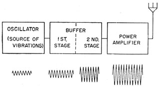
Second, what are the basic similarities? The general
plan of all transmitters can be seen in figure 117, which
shows the stages of a typical transmitter.
Every transmitter has an OSCILLATOR. It may be one
of the SELF-EXCITED jobs already studied, or it may use a
QUARTZ CRYSTAL as a source of high frequency a.c. At
best, the a.c. generated by any transmitter is feeble, and it
must be strengthened (amplified) before it has sufficient
power to carry a message any great distance.
Hence, AMPLIFIERS come next in a transmitter. There
are two types of amplifiers-VOLTAGE AMPLIFIER and
POWER AMPLIFIER. As you can see in figure 117, the voltage amplifier is the stage immediately following the oscillator. The last or OUTPUT stage is the POWER amplifier.
Figure 117.-Stages of a typical transmitter.
The stage next to the oscillator is called the
BUFFER-so named because this stage ISOLATES the oscillator from
the POWER AMPLIFIER. Without the buffer, changes in
the power amplifier due to keying or roll of your ship
would be REFLECTED back to the oscillator and cause it to
change frequency. And if the oscillator changed frequency, the person copying your messages will lose contact momentarily and thus receive an incomplete message.
The POWER AMPLIFIER lives up to its name. It increases the flow of current in the antenna so that a strong
electromagnetic carrier wave will be produced.
164
CONTINUOUS WAVE TRANSMISSIONS
The electromagnetic wave of a transmitter is like the
sound wave produced by a steamship's whistle. As long
as the valve is held open and the steam pressure holds
steady, the whistle will send out sound vibrations at one
strength and one frequency. A CONTINUOUS WAVE (C.W.)
TRANSMITTER operates in a similar manner. It sends
out a continuous stream of vibrations at radio frequency.
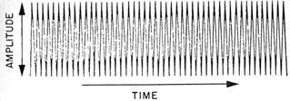
Figure 118 -Output wave of a c.w. transmitter.
The wave in figure 118 was produced by a c.w. transmitter. The oscillations are the same distance apart and
have a CONSTANT AMPLITUDE.
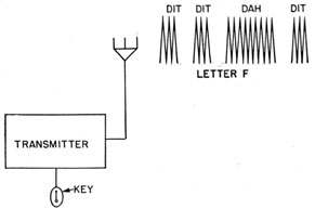
Figure 119.-How Morse code message is produced.
165
HOW TO SEND A MESSAGE WITH A CONTINUOUS WAVE
TRANSMITTER
By blowing a series of long and short blasts, you can
use your whistle to communicate with another ship. You
can do the same thing with a c.w. transmitter. By inserting a switch, or KEY, in the transmitter circuit, you
can send out long and short blasts of r.f. energy.
The output from a KEYED c.w. transmitter is given in
figure 119. When the key is held down for a short interval, a DIT will be formed. If the key is held down for a
longer period of time, a DAH will be produced. By
making a combination of dits and dahs with a key, you
can produce a Morse code signal. The (dit, dit, dah, dit)
in figure 119 is the signal for the letter F.
HOW SOUND WAVES ARE TRANSMITTED
The device used to transmit sound waves is a combination c.w. transmitter and audio amplifier.
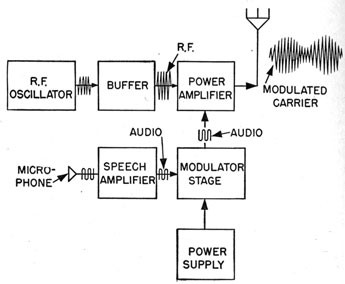
Figure 120.-Block diagram of a modulated transmitter.
166
In figure 120, the OUTPUT of the SPEECH AMPLIFIER is
fed into a MODULATOR STAGE. In this stage, the RADIO
FREQUENCY and AUDIO FREQUENCY VOLTAGES are COMBINED
to form a CARRIER WAVE that contains characteristics of
both. Notice in figure 121 that the CARRIER WAVE varies
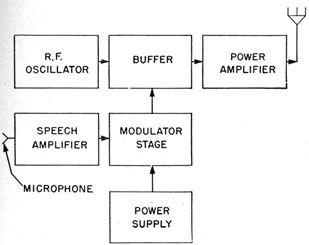
Figure 121.-Block diagram of a low-level modulated transmitter.
in amplitude in direct proportion to the SIZE and FREQUENCY of the AUDIO component.
The process of COMBINING the audio and radio frequency waves is MODULATION. The part of the modulated
carrier wave that comes from the transmitter section is
the R.F. COMPONENT, and the portion from the speech
amplifier is the A.F. COMPONENT.
If the modulation voltage is sent into the POWER AMPLIFIER stage, such a transmitter is said to be using HIGH-LEVEL MODULATION.
When the modulation voltage is sent into the BUFFER
stage, as in figure 121, the transmitter is said to be using
LOW-LEVEL MODULATION.
167
MODULATED C. W. CODE TRANSMISSION
Some code transmitters combine the characteristics
of the C.W. and MODULATED C.W. transmission.
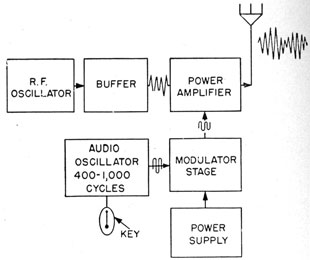
Figure 122.-Modulated C.W. code transmitter.
Figure 122 is a block diagram of a modulated c.w.
code transmitter. An AUDIO FREQUENCY OSCILLATOR,
generating a constant frequency note, is inserted in place
of a speech amplifier.
The r.f. section of the transmitter produces a CONTINUOUS CARRIER WAVE. When the key in the audio
oscillator is pressed, the audio frequency signal is sent
into the power amplifier, modulating the carrier wave.
The sound produced at the receiving end of a modulated
c.w. signal is at the frequency of the audio oscillator.
If the oscillator is generating a frequency of 400 cycles,
the frequency of the dots and dashes that you receive
will also be 400 cycles.
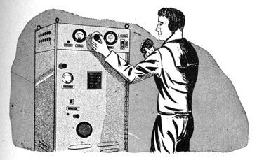
TUNING THE TRANSMITTER
About the only contact you will have with transmitter;
will be to tune them up when you change from one
168
frequency to another. If you are on a large ship where the
transmitter room is considerable distance from the radio
room, you may not get the opportunity to work with the
transmitter very often. The ETMs will have that job.
In spite of the fact that you may not have the chance to
tune them very often, you should know the correct tuning
procedure. Then you can do the job yourself in an
emergency.
Tuning a transmitter is largely a matter of following a
routine of turning dials, and closing and opening switches.
Unlike receiver operation, the operation of transmitter
controls MUST be in the PROPER SEQUENCE, otherwise you
will damage the transmitter.
In the chapter on Navy transmitters you will find brief
instructions explaining the proper method for tuning
some of the more frequently used transmitters. WHENEVER you desire more information about these or other
transmitters, study the INSTRUCTION BOOK that comes
with each set.