CHAPTER 11 RESONANCE YOU KNEW THE SPEED BY THE RATTLES
Ever sit at the wheel of your old Model A and say "Now
we're doing 40-I can tell by the rattles"? If you
changed your speed to 50 miles per hour, the rattles and
vibrations also changed. You associated the various
speeds of your automobile with the different rattles and
vibrations that were heard.
What caused those rattles? Why did certain rattles
show up at one speed and not at others?
Well, you know that all engines-even fine ones-vibrate. At different speeds, the frequencies of vibration
are different. Every fender, bumper, and bolt in your
automobile has a NATURAL FREQUENCY of vibration. If
the engine is running at the correct speed to GENERATE
the frequency of the right front fender, that fender will
vibrate. If the engine is running at a speed that will
produce the frequency of the rear bumper, that bumper
will vibrate. And so on throughout the entire automobile.
113
The phenomenon of natural vibrations is common, but
its importance is easily overlooked. It is part of every
MECHANICAL and ELECTRICAL device. Of course, you
may have trouble finding the NATURAL FREQUENCY of
vibration for some objects, but the FREQUENCY at which
an object will start vibrating is its RESONANT FREQUENCY.
SPECIAL RESONATORS
You can reinforce the sound of a musical note by using
special resonators. Resonators on xylophones are round
metal tubes; the violin has a wooden box; and the piano
has a flat sounding board. These resonators are scientifically constructed to reinforce the vibrations coming
from a weak source.
On a pipe organ or flute, the resonator is also the source
of vibration. By changing the length of pipe in the
organ or flute, the frequency (pitch) of the notes can be
changed.
ELECTRICAL RESONATORS
You will run into special resonators in electricity, too.
They will not be pipes or boxes, but just COILS and CONDENSERS in what are commonly called L-C circuits, or
"TANK CIRCUITS."
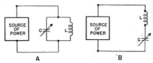
Figure 96.-Electrical resonators.
Two different ways of connecting coils and condensers
to the source of power to form ELECTRICAL RESONATORS
are given in figure 96. In drawing A, the coil and condenser are PARALLEL to each other, while in drawing B
114
the coil and condenser are in series with each other and
the source of power.
Both types of connections are used in radio circuits.
In some places they are used as a SOURCE of vibrations.
In others, they are a part of a circuit used to REINFORCE
other vibrations.
An L-C circuit that acts as a SOURCE of vibration is
called an OSCILLATOR. The circuits used to reinforce the
vibrations are called AMPLIFIERS.
WHAT HAPPENS IN AN L-C CIRCUIT
With musical resonators you may observe what is happening because you can actually FEEL and HEAR the vibrations. But in electrical resonators, you cannot observe
the action as easily, since it is an ALTERNATING CURRENT
that is GENERATED or REINFORCED.
Both mechanical and electrical resonators have several
characteristics in common. Of these, here is the most
important-neither MECHANICAL nor ELECTRICAL RESONATORS will RESPOND unless the CORRECT FREQUENCY Of
VIBRATION is PRESENT. The frequency at which a RESONATOR will RESPOND is the RESONANT FREQUENCY of the
object.
That is why your model A would rattle one way at 40.1
miles per hour, another at 42.3, and still another at 58.
Electrical resonators will not respond unless the source
of power is delivering an a.c. of the RESONANT FREQUENCY.
You learned in the chapter on coils that when a.c. is
applied to a coil, the magnetic field is continually EXPANDING and COLLAPSING.
You also learned in the chapter on condensers, that
when an a.c. is applied to a condenser, it will be continually CHARGING and
DISCHARGING.
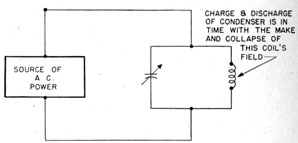
Now put the coil and condenser in an L-C circuit.
When an a.c. of a RESONANT FREQUENCY is delivered to an
L-C circuit, like the one in figure 97, the CHARGE and DISCHARGE of the condenser is IN HARMONY with the MAKE
and COLLAPSE of the coil's magnetic field.
115
At RESONANCE, the CURRENT produced by the COLLAPSE
of the field is ABSORBED in charging the condenser, and the
current from the CONDENSER'S discharge is used to build
the coil's magnetic field. As long as a current of the
Figure 97.-At resonance the coil and condenser work together.
resonant frequency is being delivered to the L-C circuit,
electrons will CIRCULATE back and forth, in and out of the
coil and condenser.
The circulation of electrons in the tank circuit is much
like the swing of a pendulum. As long as the proper
amount of energy is supplied to overcome the losses due
to friction, the swinging back and forth will continue.
In a pendulum, you INCREASE the RATE of motion by
DECREASING the length of the bar. Increasing the length
of the bar DECREASES the rate of swing.
In a tank circuit, you INCREASE the RESONANT FREQUENCY
by REDUCING the ELECTRICAL LENGTH of the L-C
circuit. And you DECREASE the electrical length by REDUCING the INDUCTANCE of the coil and the CAPACITY of
the condenser, or BOTH.
This is important
If you want to INCREASE the RESONANT FREQUENCY
of a tank circuit, you may do so by DECREASING the
CAPACITY of the condenser, or by REDUCING the
INDUCTANCE of the COIL.
If you wish to DECREASE the resonant frequency you
can do so by INCREASING the CAPACITY or INDUCTANCE.
116
MAKING USE OF RESONANCE
Each time you tune your receiver you are either increasing or decreasing the resonant frequency of the
receiver's tank circuit.
Suppose your receiver is tuned to 4,740 kc., and you
want to listen to a station on a frequency of 3,880 kc.
The receiver's resonant frequency is too high-4,740
kc.-so you twist a knob until the receiver's resonant frequency is 3,880 kc. And in comes in your station.
If you wish to bring in a station of any new frequency,
you simply adjust your receiver so that its resonant
frequency is the SAME as that of the station you want to
hear.
A VARIABLE CONDENSER DOES IT
Most receivers are tuned by adjusting a VARIABLE condenser, or several condensers ganged together on the
same shaft. CLOSING the condensers-increasing the
mesh-REDUCES the frequency. Opening the condenser
tunes the receiver to a higher frequency.
SWITCHING COILS CHANGES BANDS
As you know, most Navy receivers are made to tune
over several bands of frequencies. As an example of
this the RAL receiver which tunes from 0.3 to 23 mc. in
nine bands. To change from one band to another, you
rotate a switch. Each time you turn this switch, a DIFFERENT set of COILS are connected into the circuit.
The coils used to tune the receiver to the LOWEST band
have the GREATEST number of turns. For each successive higher frequency band, the coils have fewer and
fewer turns of wire. Thus the coils used with the HIGHEST frequency band have the LEAST number of turns.
When you rotate the switch to change bands you don't
always connect in other TUNING condensers. Usually the
same variable condenser is used to tune the LOWEST and
HIGHEST bands.
117
WHERE ELSE ARE RESONANT CIRCUITS USED?
Transmitters also contain many resonant circuits.
Most Navy transmitters use a tank circuit to GENERATE
an a.c. of radio frequencies. This part of a receiver is
the OSCILLATOR. You change the frequency of the oscillator by changing either the capacity of the condensers
or the inductance of the coils.
In addition to the transmitter's OSCILLATOR, other tank
circuits are used to STRENGTHEN, or AMPLIFY, the oscillator's feeble a.c. You will hear more about this later
in this manual.