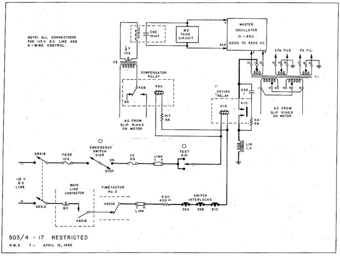
(c) With the equipment ready for operation, the main line switch (S-831), the EMERGENCY SWITCH (S-12) and the main line contactor contacts K-831B all are closed.
2. OPERATION:
(a) When the TEST key (S-10) is closed, the keying relay coil (K-1A) will be energized.
(1) The keying relay main contacts (K-1C) ground the center tap of the MO filament secondary of T-1 to complete the DC return path to the filament and allow the MO to oscillate.
(b) The compensator relay coil (K-2A) in parallel with K-1A will also be energized whenever the TEST key (S-10) is closed.
(1) Contacts K-2B connect the AC supply to the compensator transformer (T-3) to heat the compensating capacitor (C-62). This capacitor is a bi-metallic device which compensates for the changes in MD circuit capacity due to the expansion of tube elements under key-down conditions.
(c) When the key is open, both relays (K-1 and K-2) are de-energized.
20
TRANSMITTER SERVICING
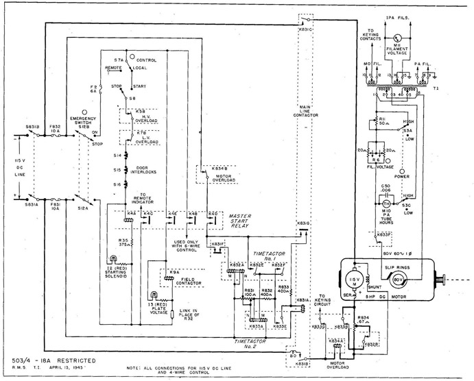
Fig. 18 TBK-13 Transmitter (DC Model) Control and Power Circuits.
STARTING THE TRANSMITTER
1. Main line switch (S-831) and EMERGENCY SWITCH (S-12) both closed.
3. Master start contacts K-4E energize the field contactor coil (K-9A).
(a) Field contacts (K-9B and C) connect the HV and LV generator fields to the 275-v DC generator armature.
4. Master start contacts K-4D energize main coil (K-832A) of Timetactor No. 1.
(a) Timetactor No. 1 contacts K-832B (across part of the motor starting resistance R-834) open.
5. Timetactor No. 1 contacts K-832E energize main coil (K-833A) of Timetactor No. 2.
(a) Timetactor No. 2 contacts K-833B (across all of the starting resistance R-834) open.
6. Timetactor No. 2 contacts K-833E energize main line contactor coil (K-831A) through previously closed contacts K-832F, K-832E and K-4D.
7. Main line contacts K-831B and C connect the 115-v DC line to the motor through starting resistance (R-834).
(a) Holding contacts K-831G connect R-833 in series with coil K-831A.
(b) Contacts K-831F disconnect main coil (K-832A) of Timetactor No. 1.
21
TBK-13 TRANSMITTER
8. After a few seconds delay, Timetactor No. 1 becomes de-energized.
(a) K-832B short out part of the starting resistance (R-834).
(b) K-832E disconnect the main coil (K-833A) of Timetactor No. 2.
9. After another few seconds delay, Timetactor No. 2 becomes de-energized.
(a) K-833B short out all of the starting resistance (R-834).
(b) K-833F connect the filament transformer (T-I) to 80 v AC from the slip rings on the DC motor.
ADJUSTING THE TRANSMITTER SUPPLY VOLTAGES
1. Filament voltage should be adjusted with FILAMENT VOLTAGE control (R-6) for 10 v on FILAMENT VOLTAGE meter (M-11).
2. High plate voltage_-should be adjusted with GENERATOR FIELD control (R-33) for 3,000 v on PA PLATE VOLTAGE meter (M-9), with the TUNE-OPERATE switch (S-9A) in OPERATE position.
(a) K-4D disconnect the main line contactor coil (K-83IA).
(b) K-831B and C disconnect the motor from the line.
22
TRANSMITTER SERVICING
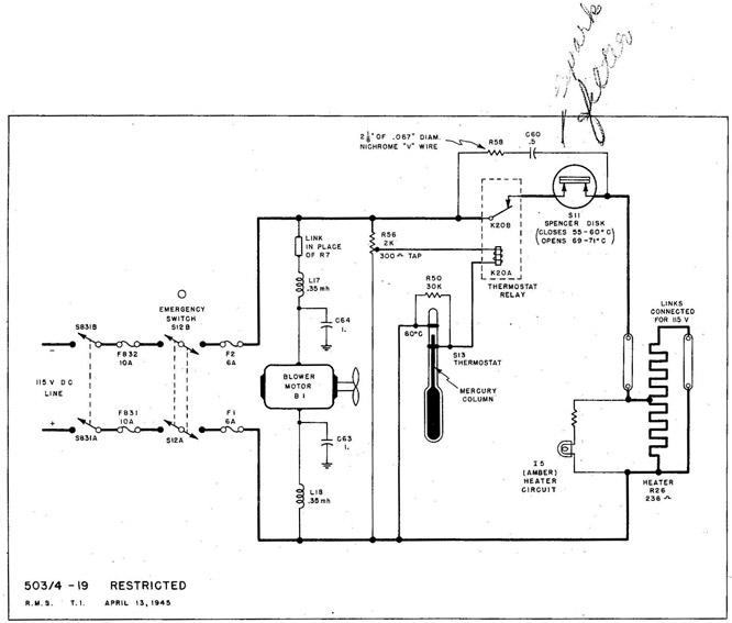
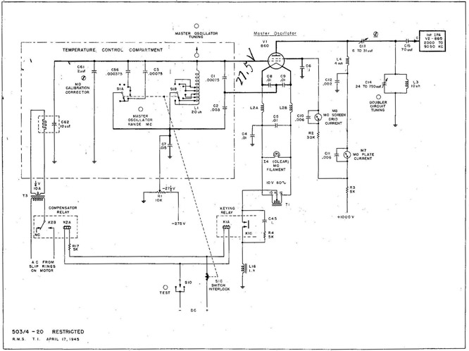
Fig. 19 TBK-13 Transmitter (DC Model) MO Temperature Compartment.
1. PURPOSE: To improve the MO frequency stability by maintaining critical MO circuit elements at a practically constant temperature.
2. OPERATION:
(a) Closing main line switch (S-831) and EMERGENCY SWITCH (S-12) starts the blower motor (B-1), to circulate the air within the compartment.
(1) RF hash interference to radio equipment nearby is eliminated by the two filters (L-17, C-64 and L-18, C-63).
(b) If the temperature in the compartment is below 60° C, the thermostat (S-13) contacts are open, preventing the thermostat relay (K-20) from being energized. The heating element (R-26) is energized through the normally closed contacts (K-20B) of the thermostat relay.
(c) When the temperature in the compartment reaches 60° C, the mercury column of the thermostat (S-13) completes the circuit to the thermostat relay coil (K-20A).
(1) Contacts K-20B open to turn off the heating element (R-26).
(d) As soon as the temperature within the compartment falls a small fraction of a degree below 60° C, the heating cycle is repeated.
(e) If either S-13 or K-20 fail to operate, the temperature protection switch (bi-metallic Spencer Disk S-11) will turn the heating element (R-26) off and on within the limits of 71° and 55° C.
1. PURPOSE: To provide a signal of 2,000 to 4,525 kc with excellent frequency stability and sufficient power to drive the first IPA.
2. GENERAL CIRCUIT CONDITIONS: An electron coupled circuit, Class C, with plate circuit always tuned to the second harmonic of the grid - screen grid circuit.
3. OPERATION:
(a) MO frequency is controlled by the grid - screen grid circuit L-1; C-1, C-2, C-3, C-56, C-61 and C-62.
(1) Coarse tuning in 8 steps with MASTER OSCILLATOR RANGE MC control (S-1). Switch interlock contacts S-1C break the keying circuit while S-1A and B are between steps.
(2) Vernier tuning with MASTER OSCILLATOR TUNING control (a - copper cylinder on a threaded shaft inside L-1L.
(b) MO CALIBRATION CORRECTOR capacitor (C-61) should be set half open before the transmitter is calibrated. When MO tubes or parts are changed, C-61 may be adjusted to make the MO frequency correspond to the previously calibrated settings.
(c) Bi-metallic compensating capacitor (C-62), heated by current from T-3 whenever the key is closed, compensates for changes in MO circuit capacity due to expansion of tube elements under operating conditions.
24
TRANSMITTER SERVICING
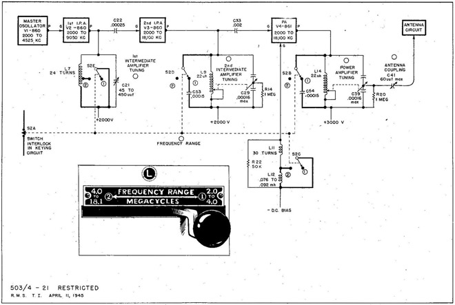
Fig. 21 TBK-13 Transmitter FREQUENCY RANGE Control
1. PURPOSE: To provide two tuning ranges, (1) from 2.0 to 4.0 mc, and (2) from 4.0 to 18.1 mc.
2. OPERATION WITH FREQUENCY RANGE control (S72) in position (1) 2.0 to 4.0 mc;
(a) S-2E connects all of the inductance (L-7) into the 1st IPA plate tank circuit for the lower frequency range.
(b) S-2D connects a fixed capacitor (C-53) across the 2nd IPA tank.
(c) S-2B connects a fixed capacitor (C-54) across the FA tank.
(d) S-2C connects an additional RF choke (L-12) in the grid circuit of the PA to provide sufficient impedance at the lower frequencies.
(e) S-2A (switch interlock) opens the keying relay coil circuit while the main contacts (S-2B, C, D and E) are between positions.
3. OPERATION WITH FREQUENCY RANGE control (S-2) in position (2) 4.0 to 18.1 mc:
(a) S-2E shorts out part of the 1st IPA plate tank inductance (L-7) for the higher frequency range.
(b) S-2D disconnects the fixed capacitor (C-53) from the 2nd IPA tank.
(c) S-2B disconnects the fixed capacitor (C-54) from the PA tank.
(d) S-2C shorts out the additional RF choke (L=12) in the PA grid circuit so L-11 will provide the correct impedance for the higher frequency range.
(e) S-2A (switch interlock) opens the keying relay coil circuit while the main contacts (S-2B, C, D and E) are between positions.
25
TBK-13 TRANSMITTER
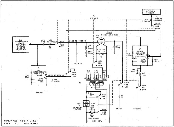
Fig. 22 TBK-13 Transmitter (DC Model) High 7 Low POWER Control
1. PURPOSE: To provide two power outputs, 500 watts and 75 watts.
2. GENERAL CIRCUIT CONDITIONS: Parts concerned only with the 2.0 to 4.0 mc range have been omitted from Fig. 22.
3. OPERATION WITH POWER control (S-2, S-3, S-4 and S-5) in HIGH position:
(a) S-3B connects the final FA filament.
(b) S-3A shorts out the low power filament resistor (R-11).
(c) S-3C connects the FA TUBE HOURS meter (M-10).
(d) S-4A connects the final PA grid to the output of the 2nd IPA. (e). S-5B connects the final PA screen to the DC power supply.
(f) S-5C connects the final FA plate to the DC power supply.
(g) S-5A connects the antenna to the final PA plate tank circuit.
(h) S-4B disconnects the antenna from the 2nd IPA plate tank circuit.
(i) S-2A (switch interlock) breaks the keying relay coil circuit while all the main contacts of the POWER control are between positions.
4. OPERATION WITH POWER control (S-2, S-3, S-4 and S-5) in LOW position:
(a) S-3B and S-3A disconnect the PA filament and connect the low power filament resistor (R-11) in series with the primary of filament transformer (T-1) to maintain 10 volts on the remaining filaments.,
(b) S-3C disconnects the FA TUBE HOURS meter (M-10).
(c) S-4A, S-5B and S-5C disconnect the PA grid, screen and plate.
(d) S-5A and S-4B transfer the antenna from the FA to the 2nd IPA.
26
TRANSMITTER SERVICING
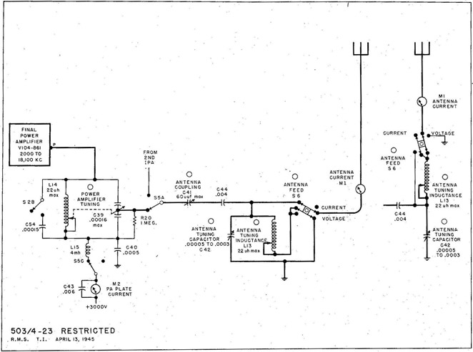
Fig. 23 TBK-13 Transmitter Antenna Circuit.
1. PURPOSE: To tune the antenna circuit to resonance and to couple the desired amount of RF power from the transmitter to the antenna.
(a) CURRENT FEED: To couple the transmitter output to an antenna that is nearest to an odd multiple of quarter wavelengths.
(b) VOLTAGE FEED: To couple the transmitter output to an antenna that is nearest to an even multiple of quarter wavelengths.
2. OPERATION:
(a) With the ANTENNA FEED switch (S-6) in CURRENT FEED position, the antenna tuning inductance (L-13) and the antenna tuning capacitor (C-42) are connected in a series circuit.
(b) With the ANTENNA FEED Switch (S-6) in VOLTAGE FEED position, L-13 and C-42 are connected in a parallel circuit.
(c) The degree of coupling between the transmitter and the antenna is adjusted with the ANTENNA COUPLING control (C-41). Increased coupling should cause an increase in PA PLATE CURRENT (M-2).
(d) Coarse antenna tuning is done with ANTENNA TUNING INDUCTANCE control (L-13), for a rise in FA PLATE CURRENT (M-2).
(e) Vernier antenna tuning is done with ANTENNA TUNING CAPACITOR control (C-42), for a peak in PA PLATE CURRENT (M-2).
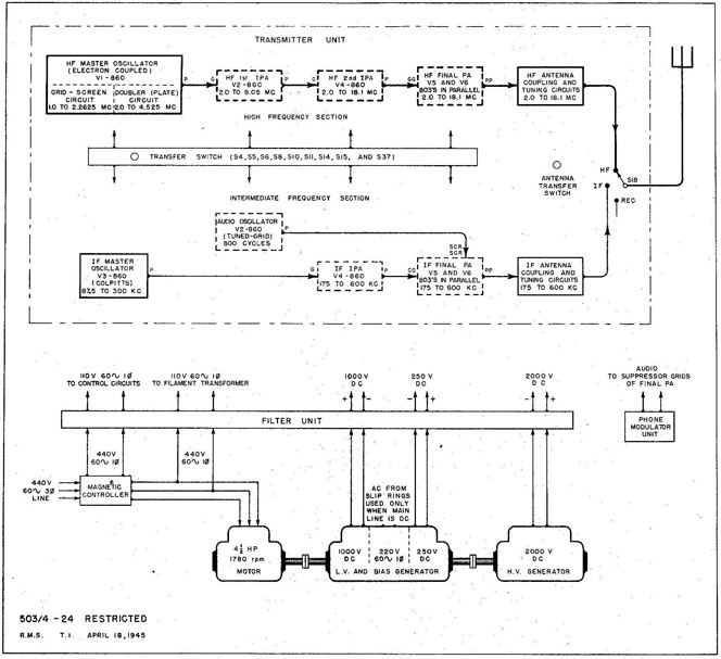
1. PURPOSE: To provide general communication for small ships.
2. FREQUENCY RANGES:
(a) IF, 175 to 600 kc.
(b) HF 2,000 to 18,100 kc.
3. EMISSION:
(a) A-1 or CW up to 100 words per minute.
(b) A-2 or MCW on IF range only, up to 100 words per minute.
(c) A-3 or PHONE up to 85% modulation.
4. POWER OUTPUTS:
(a) From 50 to 200 watts variable on CW.
(b) 100 watts on MCW.
(c) 50 watts on PHONE.
28
TRANSMITTER SERVICING
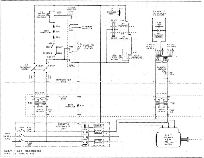
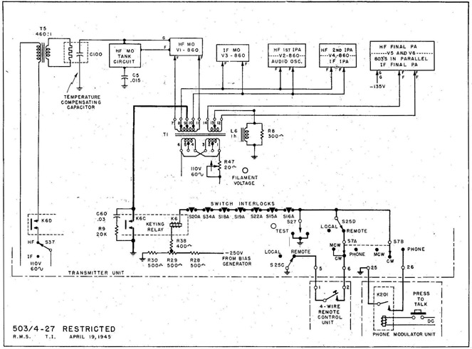
Fig. 25 TBL-7 Transmitter (AC Model) Control and Power Circuits.
1. PURPOSE: To simplify starting and stopping the transmitter, and to convert the line supply to the types of power required by the transmitter.
2. GENERAL CIRCUIT CONDITIONS:
(a) Transmitter control circuits connected for Navy 4-wire control unit.
(b) Main line switch (S-331) and EMERGENCY SWITCH (S-24) both closed.
3. STARTING THE TRANSMITTER:
(a) Close START-STOP switch (S-26) to energize master start relay (K-13).
(b) Master start contacts K-13A energize the main line contactor (K-331).
(1) Main line contacts (K-331B, C and D) connect the line to the AC motor and to filament power transformer (T-151).
(c) Master start contacts K-13A also energize field contactor (K-16).
(1) Field contacts (K-16A and B) connect the LV and HV generator shunt fields to the 250-v DC bias generator armature.
4. ADJUSTING TRE TRANSMITTER SUPPLY VOLTAGES:
(a) Filament voltage on all tubes should be correct when FILAMENT VOLTAGE
29
TBL-7 TRANSMITTER
control (R-47) is adjusted for 10 v on FILAMENT VOLTAGE meter (M4).
(b) High plate voltage should be adjusted with PLATE VOLTAGE control (R-41) for 2,000 v on PLATE VOLTAGE meter (M-10) with TUNE-OPERATE-switch (S-22) in OPERATE position.
(c) Bias and MO plate voltages adjustable only with tap on R-150.
5. OVERLOAD PROTECTION:
(a) Momentary overload in either the 1,000-v or the 2,000-v DC generator output will trip either the LV (K-17) or the HV (K-18)-overload relay.
(1) Overload contacts (K-17 or K-18) de-energize K-16 coil.
(2) K-16A and B disconnect both generator shunt fields.
(b) Prolonged overload on the AC motor will trip thermal overload relay (K-332) in the magnetic controller unit.
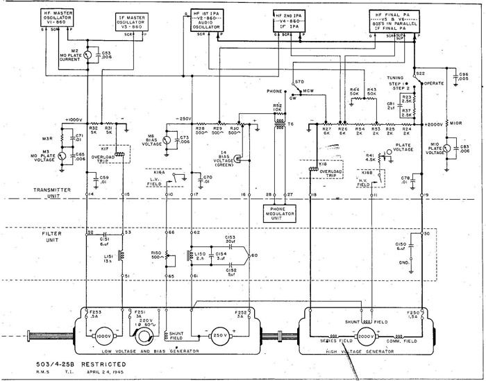
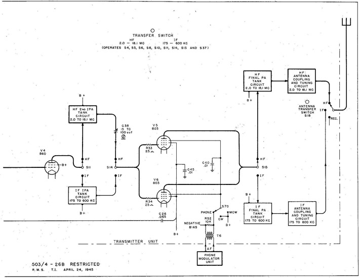
1, PURPOSE: To control the RF output of the transmitter'.
2. GENERAL CIRCUIT CONDITIONS: With no signal, the final PA tubes (V-5 and V-6) are biased beyond cutoff with -135 volts of fixed bias.-
3. OPERATION:
(a) Closing any of the following energizes the keying relay (K-6):
(1) TEST key (S-27).
(2) Remote key when REMOTE - LOCAL switch (S-25) is in REMOTE and PHONE - CW - MCW switch (S-7) is in CW or MCW.
(3) PRESS TO TALK Switch and K-201 contacts in the phone modulator unit when PHONE - CW - MCW switch (S-7) is in PHONE.
(b) Keying relay contacts K-6C complete the DC return path to the filaments of all stage's except the final PA. The PA filament return is always complete through the key thump filter (L-6 and R-8).
(c) Keying relay contacts K-6D energize the compensator transformer (T-5) which heats bi-metallic temperature compensating capacitor (C-100).
(d) Opening the key or press to talk switch de-energizes K-6.
(1) K-6C break the filament return of all stages except the PA.
(2) K-6D disconnect the compensator transformer (T-5).
(e) C-60 and R-9 are a key click filter.
33
TBL-7 TRANSMITTER
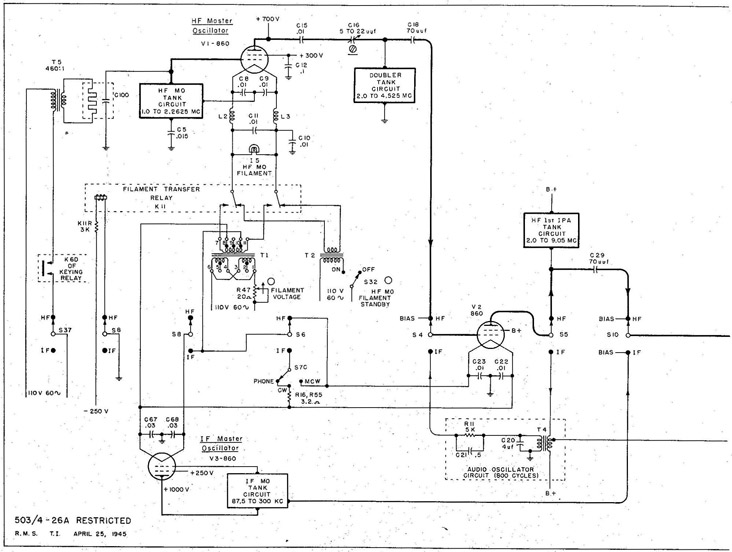
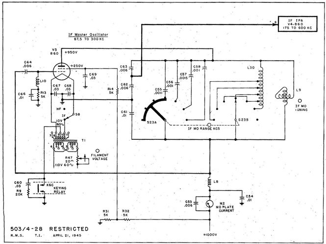
Fig. 28 TBL-7 Transmitter (AC Model) IF Master Oscillator.
IF MASTER OSCILLATOR (87.5 to 300 kc)
1. PURPOSE: To generate an RF signal at any desired frequency from 87.5 to 300 kc.
2. GENERAL CIRCUIT CONDITIONS: Series-fed standard Colpitts type, Class C.
(3) RF output taken from capacitive voltage divider (C-61, C-62 and C-63).
3. OPERATION:
(a) Coarse tuning in 7 steps with IF MO RANGE KCS control (S-23).
(b) Vernier tuning with IF MO TUNING control (variometer L-9).
IF INTERMEDIATE FOYER AMPLIFIER. (175 to 600 kc)
1. PURPOSE: To amplify the RF output of the MO, and to isolate the MO from the PA.
2. GENERAL CIRCUIT CONDITIONS: Class C, always operated as a frequency doubler.
34
TRANSMITTER SERVICING
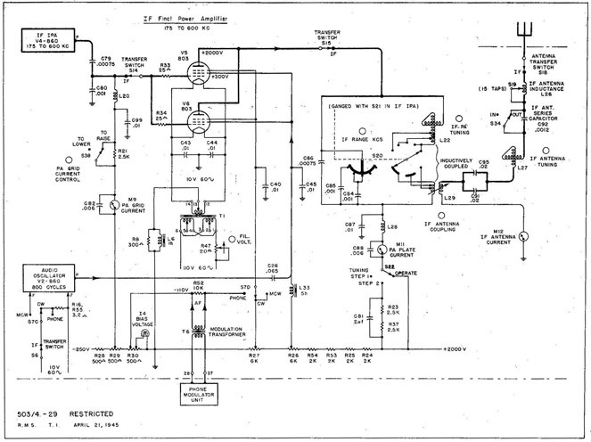
Fig. 29 TBL-7 Transmitter IF Final Power Amplifier.
IF FINAL POWER AMPLIFIER (175 to 600 kc)
1. PURPOSE: To deliver a maximum of 200 watts of RF power to the antenna circuit.
2. GENERAL CIRCUIT CONDITIONS:
(a) Two 803's in parallel, Class C.
(b) R-33 and R-34 in the grid circuit are parasitic suppressors.
(c) For MCW operation, the PA tubes are screen-grid modulated by the 800-cycle audio oscillator (V-2).
(d) For PHONE operation, the PA tubes are suppressor-grid modulated by the output of a separate Phone modulator unit.
(e) The antenna circuit is always series-tuned.
3. OPERATION:
(a) Coarse tuning in 5 steps with IF RANGE RCS control (S-20). .
(b) Vernier tuning with IF PA TUNING control (variometer L-22).
(c) Inductive antenna coupling with IF ANTENNA COUPLING control (L-29).
TBL-7 HF TRANSMITTER (2.0 to 18.1 mc)
The TBL-7 HF transmitter is very similar to the TBK-13. The main differences are: 200 watts maximum output, parallel 803's in the PA, and 50 watts PHONE emission.