Transmitter Servicing Course 503/4, 1945, is a training manual that focuses on WW II naval transmitters TAJ, TBK, TBL, TDE and TBS.
Thank you Rob Flory for providing a scan of the manual.
In this online version of the manual we have
attempted to keep the flavor of the original layout while taking advantage
of the Web's universal accessibility. Different browsers and fonts will cause
the text to move, but the text will remain roughly where it is in the
original manual. In addition to errors we have attempted to preserve from the original,
this text was captured by a combination of optical character recognition
and human typist. Each method creates errors that are compounded while
encoding for the Web.Please report any typos, or particularly annoying layout issues with the Mail Feedback Form for correction.
Richard Pekelney
Webmaster
RESTRICTED
TRANSMITTER SERVICING
COURSE 503/4
NAVAL TRAINING SCHOOL
(RADIO MATERIAL)
TREASURE ISLAND
SAN FRANCISCO, CALIFORNIA
MAY 1945
1
COURSE 503114
TRANSMITTER SERVICING
The transmitters covered in this book are communication type, for transmitting CW, MCW and PHONE signals.
INSTRUCTION BOOKS
1. PURPOSE: To provide information for installing, operating, maintaining and servicing specific equipment.
2. GENERAL CONTENTS:
(a) Safety precautions.
(b) Introduction to equipment.
(c) Manufacturers' guarantee.
(d) Description of equipment.
(e) Installation.
(f) Operation.
(g) Maintenance.
(h) List of major units.
(i) Spare parts list.
(j) Diagrams and illustrations.
3. WHERE TO OBTAIN: Two instruction books should accompany each equipment. If not packed with the equipment, the books may be mailed to the Commanding Officer. Ask for them through the Communications or Security Officer.
4. USE OF INSTRUCTION BOOKS:
(a) As study material from which the technician can make his own servicing block and simplified schematic diagrams.
(b) As a guide in setting up a regular maintenance schedule.
(c) As a reference during installation and servicing.
5. TYPICAL TEST DATA: Usually two copies of typical test data are furnished with each set of instruction books- This data is compiled from extensive performance tests and measurements taken at the factory, and is a reliable guide to normal operation of the equipment. Typical test data includes:
(a) Frequency tests.
(b) Control circuit tests.
(c) Power output tests,
(d) Emission tests.
(e) Vibration and shock tests.
(f) Voltage and current measurements.
As many as possible of these tests should be duplicated with the ship's own test equipment after the installation is complete and is working properly. A permanent record of such tests should be kept in the equipment log.
2
TRANSMITTER SERVICING
RADIO EQUIPMENT LOG BOOK
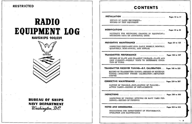
1. PURPOSE: The new log furnished by the Bureau of Ships is a permanently bound book of 335 pages, designed to record a complete history of all equipment in an average radio room for two years. The log book replaces the Communication Equipment Index and Communication Equipment History card files.
Fig. 1 Front Cover and Contents of Radio Equipment Log Book.
2. WHERE TO OBTAIN: The log book has been distributed to all ships and stations on the basis of one for each radio space. More copies may be obtained from Radio Materiel Officers or from the Bureau of Ships.
3. USE: The blank forms in the log book are designed to cover all routine inspections and tests required by Chapter 67 of the Bureau of Ships Manual (formerly Chapter 31 of the Manual of Engineering Instructions). Special inspections and tests required by individual equipments, outlined in the manufacturers' instruction books, should be added to the log. Official modifications and improvements announced in al Ships Communication Equipment Maintenance Bulletins (CEMB) are to be made and logged without further notification.
A Sonar Equipment Log book has been issued, and a Radar Equipment Log book will be issued for similar use with Sonar and Radar equipment. The counterparts of the Communication Equipment Maintenance Bulletins (CEMB) are: Sonar Maintenance Bulletins (SMB) and Radar Maintenance Bulletins (RMB).
3
RECORDS AND REPORTS
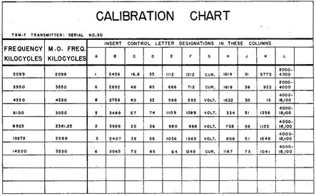
CALIBRATION CHARTS: A calibration chart similar to the one in Fig. 2 is mounted on the front panel of each transmitter to provide, for immediate reference, all tuning dial settings for several of the most important frequencies used. Additional charts are included in the Radio Equipment Log Book for recording dial settings of many more frequencies. The original dial settings are Obtained by first tuning the transmitter very carefully to each desired frequency. Repeat settings then may be made from the charted readings without checking with a frequency meter and instruction book tuning curves. Charted readings should be checked and corrected where necessary after any replacement of tubes or parts, any severe shock, changes in antenna characteristics, etc.
Fig. 2 Typical Calibration Chart for front panel of transmitter.
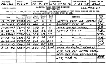
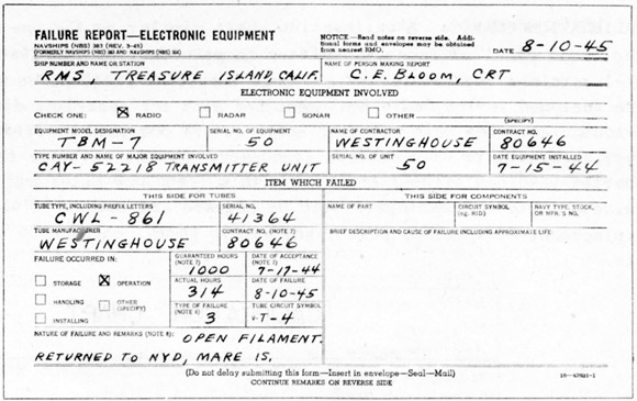
VACUUM TUBE SERVICE RECORDS: A vacuum tube service record such as the one shown in Fig. 3 must be kept for at least each Service Life Guaranteed tube, each special Radar tube, and each transmitting tube of the class of types 849, 851, 861 and larger. These cards then provide the necessary information for filling out the official report of vacuum tube failure on the new FAILURE REPORT - ELECTRONIC EQUIPMENT, revised 3-45, shown in Fig. 4.
Fig. 3 Sample Vacuum Tube Service Record Card.
4
TRANSMITTER SERVICING
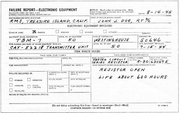
Front, as used for reporting vacuum tube failures.
(a) Never clean commutators or work on a machine while it is running.
(b) Use only fine sandpaper to smooth commutators; never use emery cloth or other conducting. abrasives.
(c) Keep both the interior and exterior of Machines, panels and control boxes clean.
(d) Keep all electrical connections tight.
(e) Inspect machines during each watch. If any unit is not operating properly it should be shut down and the defect remedied.
(f) Keep protective devices such as circuit breakers, fuses and inter-locks in working order and operating at their proper settings. .
(g) After an overhaul, never start a machine until a careful inspection has been made for loose bolts, tools, broken insulation, metallic dust or chips, improper clearance, loose or improper connections, and lubrication.
(h) When a motor or generator bearing overheats, flush it with new lubricant and cool it before the machine is stopped, to avoid freezing the bearing to the journal.
2. VISUAL INSPECTIONS: Many defects can be discovered quickly without making extensive tests or electrical measurements.
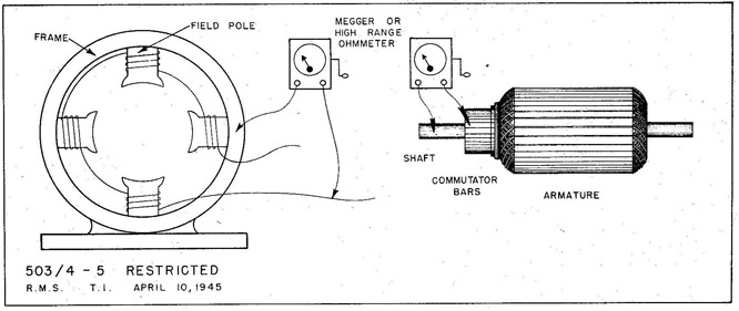
3. TESTING FOR LEAKY INSULATION AND GROUNDED COILS:
(a) Remove brushes and other connections from field coil leads to avoid parallel circuits in testing.
(b) Make insulation tests as shown in Fig. 5, using a megger or a high range Ohmmeter.
(c) Normal reading should be several megohms.
(d) Absorbed moisture may cause the insulation resistance to be as low as one megohm. Dry thoroughly by plow heating or baking.
(e) A reading of less than one megohm indicates defective insulation. Isolate the defective coil or commutator bar by testing each one individually.
Fig. 5 Testing for leaky insulation and grounded coils.
6
TRANSMITTER SERVICING
4. ARMATURE AND FIELD COIL FAILURES:
(a) Mechanical defects may be worn bearings, loose or sagged windings, exposed mica segments or otherwise rough, uneven commutators.
(b) Electrical defects may be open coils or connections, shorted coils, or grounded coils.
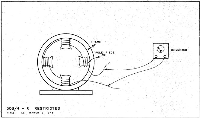
5. TESTING FOR OPEN OR SHORTED FIELD COILS:
(a) Remove brushes and other connections from field coil leads to avoid parallel circuits in testing.
(b) Test with an ohmmeter as shown in Fig. 6.
(c) No continuity indicates an open coil. Isolate the defective coil by testing each coil individually.
(d) Continuity, even with approximately correct resistance, for all coils in series does not eliminate the possibility of a shorted coil. Test each coil individually. One reading appreciably less than the others indicates a shorted or partially shorted coil. Visual inspection usually reveals signs of overheating.
(e) Spare field coils are often supplied With the equipment, and may be installed by the technician without special tools.
Fig. 6 Testing for open or shorted field coils.
7
MOTOR-GENERATOR SERVICING
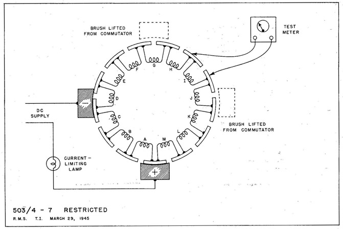
6. TESTING FOR OPEN OR SHORTED ARMATURE COILS:
(a) Lift all but one set of brushes free of the commutator.
(b) Apply DC through a current limiting lamp as shown in Fig. 7. The test current divides into two parallel paths, one through coils A, B and C; the other through coils E, F, G, H, I, J, K, L and M (coil D in Fig. 7 is shorted by the negative brush).
(c) The test meter should be a milliammeter with a range appropriate for the test current.
(d) All bar to bar measurements between adjacent commutator bars in the current path including coils E to M should give practically identical readings. To obtain similar readings on coils A to D, rotate the armature to bring these coils into the same current path.
(1) An open coil causes a high reading across that coil, but zero across all others in the same current path
(2) A short in a coil or between commutator bars causes a low or zero reading across the defect, and slightly higher than normal readings across all other test points in the same current path.
(e) If the resistance of individual armature coils is high enough to give satisfactory readings on an ohmmeter, similar bar to bar measurements may be made without an external source of DC
(f) Armature repairs are difficult to make, and should be done by a repair ship or Navy yard shop if possible.
Fig. 7 Testing for open or shorted armature coils.
8
TRANSMITTER SERVICING
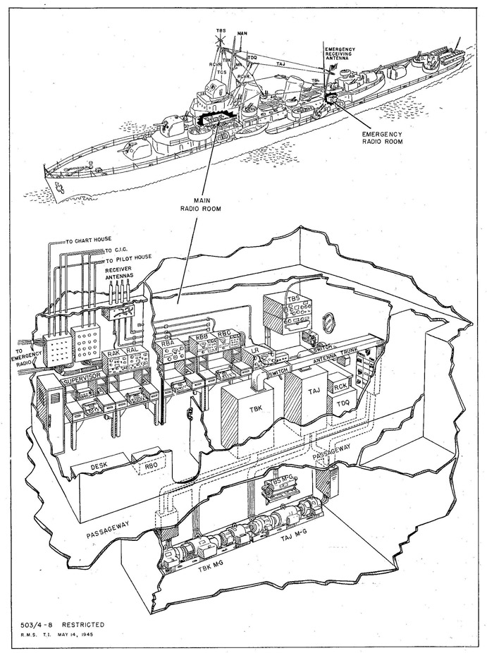
Fig. 8 A typical shipboard installation of communication transmitting equipment.
9
A TYPICAL SHIPBOARD INSTALLATION OF COMMUNICATION TRANSMITTING EQUIPMENT
The installation described here is based on that of a large destroyer. The details of individual installations vary widely, especially in older ships where electronic equipment has outgrown the original construction plans. Therefore the following typical arrangement applies only in general.
MAIN RADIO ROOM
EMERGENCY RADIO ROOM
CIC
PILOT HOUSE
TRANSMITTERS
TAJ TBK TBS TDQ
TBL with modulator and speech input eq.
TCS MN
MAN
RECEIVERS
TBS, RCK RBA-RBB-RBC RAK-RAL RBO
RAK-RAL
ICS MN RBH
MAN
REMOTE CONTROL UNITS
3 Navy STANDARD 1 TBS
1 Navy STANDARD 1 TBL Phone
2 Navy STANDARD 1 TBL phone 1 TBS 1 TDQ
1 Navy STANDARD 1 TBL phone 1 TBS 1 TDQ, 1 MN
TRANSFER PANELS
Transmitter Receiver
Transmitter Receiver
FREQUENCY METER
1 LR
MOTOR GENERATORS: If the transmitter motor generators cannot be located as shown, they should be as near the transmitters as possible without being in the same room.
POWER PANEL: A changeover switch in the main radio room permits operation of all equipment from either the main generators or the emergency diesel power plant.
ANTENNAS: The large transmitting antennas enter the radio rooms through protective trunks, with an antenna disconnect and grounding switch at the transmitter end. The TBS, TDQ. MN and MAN antennas are mounted on the foremast and are connected to the transceivers with coaxial transmission line. Four receiving antennas, two port and two starboard, are suspended from the foremast yard arm. A 30-foot whip antenna serves the emergency radio receivers.
TRANSFER PANELS: Except for the small transceivers intended primarily for voice communication, all transmitters, receivers and Navy standard remote control units are wired to transfer panels. Patch cords may be plugged so any control unit can operate any transmitter, and any receiver output can be connected to any operating position.
10
TRANSMITTER SERVICING
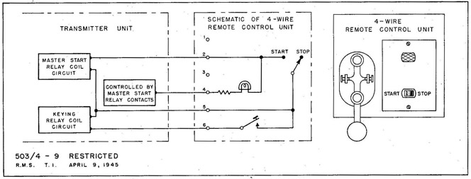
NAVY STANDARD REMOTE CONTROL UNITS
1. PURPOSE: To start, key and stop transmitters from a remote operating position.
2. 4-WIRE SYSTEM:
(a) Toggle type start-stop switch.
(b) One wire is common to start-stop and keying circuits.
Fig. 9 Navy Standard 4-Wire Remote Control Unit.
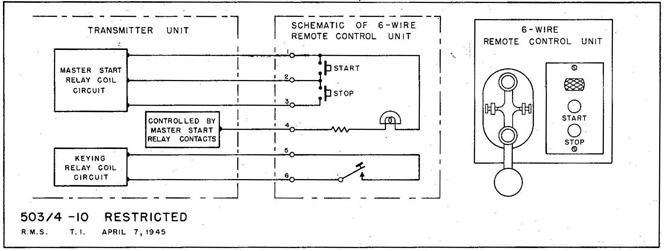
3. 6-WIRE SYSTEM:
(a) Momentary push-button type start-stop switches.
(b) Start-stop and keying circuits are isolated from each other.
(c) Additional control units in parallel on same line provide complete control at any unit.
Fig. 10 Navy Standard 6-Wire Remote Control Unit.
4. CONVERSION FROM ONE SYSTEM TO THE OTHER: Any one ship uses either all 4-wire or all 6-wire controls. Transmitters may be converted by changing link connections according to the instruction book.
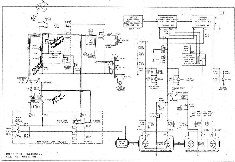
(d) The holding contacts (K-104B) keep the master start relay energized after the START button is released.
(e) The POWER indicator lamp (I-101) remains on as long as K-104 is energized.
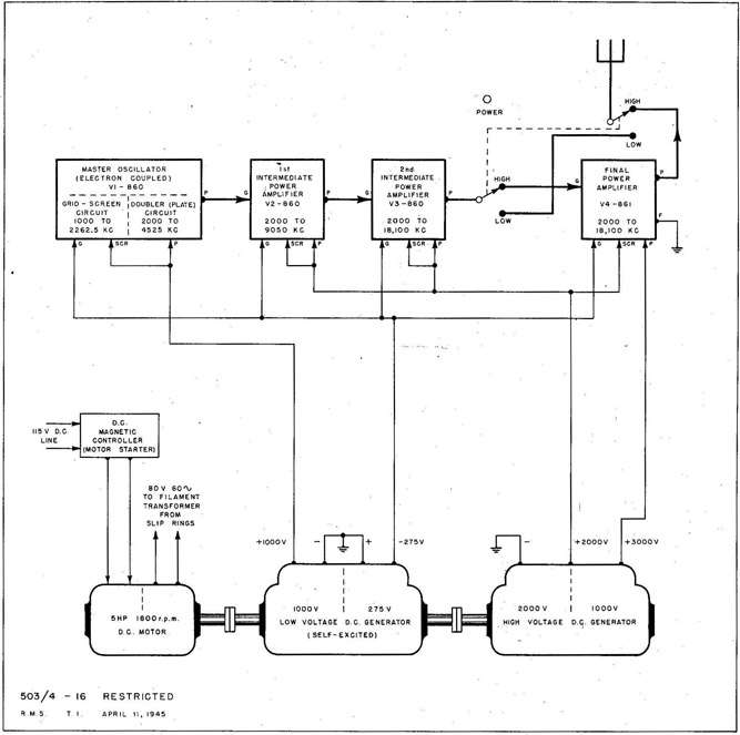
(f) The master start contacts K-104A energize the main line contactor, which closes the main line contacts to connect 440 v 3 Φ AC to the motor.
(g) The motor drives both the LV and the HV DC generators.
(h) The master start contacts K-104C energize the filament transformers (T-101 and T-102) from the line transformer (T-103).
(i) The master start contacts K-104D allow the shunt field of the LV DC generator to be self-excited from the 115-v DC armature.
3. ADJUSTING THE TRANSMITTER SUPPLY VOLTAGES:
(a) Filament voltage should be adjusted with MAIN FILAMENT control (R-123; R-133) for 11 v on FILAMENT VOLTAGE meter (M-106). -
(b) Bias voltage should be adjusted with BIAS FIELD control (R-125) for 115 v on BIAS VOLTAGE meter (M-107).
(c) High plate voltage should be adjusted with MAIN FIELD control (R-124) for 3000 v on PLATE VOLT-AGE meter (M-I09), with the TUNE-OPERATE switch (S-106) in OPERATE position.
(b) The holding contacts (K-104B) open, to keep the master start relay de-energized.
(c) Contacts K-104A de-energize the ma in line contactor, to disconnect the motor.
(d) Contacts K-104C disconnect the filament transformers (T-101 and T-102).
(e) Contacts K-104D disconnect the shunt field of the LV DC generator.
5. MASTER OSCILLATOR FILAMENT STANDBY:
(a) With MO FIL. standby switch (S-109) in TRANS. position, the MO filament is on only when the transmitter is on.
(b) With S-109 in LINE position, the MO filament transformer (T-102) is energized through R-122 and the normally closed contacts K-104E while all other operating voltages are disconnected.
14
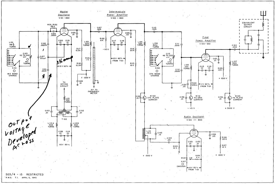
Fig. 13 TAJ-18 Transmitter RF and AF Circuits.
15
TAJ-18 RF AND AF CIRCUITS
RF STAGES (ALL CLASS C)
1. MASTER OSCILLATOR (MO):
(a) Electron coupled type.
(b) Tuning range from 175 to 600 kilocycles.
(1) Coarse tuning in 7 steps with MO BAND CHANGE switch (S-101).
(2) Fine tuning with MO TUNING control (C-103).
(c) Frequency drift with changes in room temperature is compensated for by the negative temperature coefficient capacitor (C-157).
(d) The untuned plate circuit has a practically uniform frequency response over the entire 175 to 600 kc operating range.
2. INTERMEDIATE POWER AMPLIFIER (IPA):
(a) Tuning range from 175 to 600 kilocycles.
(1) Coarse tuning in seven steps with IPA, BAND CHANGE switch (S-102).
(2) Fine tuning with IPA TUNING control (C-113).
(b) For MCW operation, the IPA is plate modulated by the AUDIO OSCILLATOR (V7104).
3. FINAL POWER AMPLIFIER (PA):
(a) Tuning range from 175 to 600 kilocycles in the same manner as the IPA. The details omitted from the equivalent output circuit in Fig. 13 are shown in Fig. 14.
(b) For MCW operation, the negative grid bias is held constant over the audio cycle by the AF bypass capacitor (C-I55).
AUDIO OSCILLATOR (AO)
(a) Hartley type.
(b) Frequency 800 cycles.
(c) For CW operation, the EMISSION selector switch (S-107) turns off the AO filament and substitutes R-126.
16
TRANSMITTER SERVICING
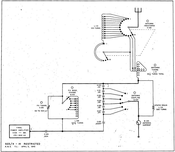
Fig. 14 TAJ-18 Transmitter Antenna Circuit.
1. PURPOSE: To match the impedance of the antenna to the impedance of the final RF power amplifier (V-103), and to tune the antenna to resonance.
2. COUPLING: The degree of coupling between the antenna and the transmitter is adjusted in 6 steps with ANTENNA,COUPLING control (S-104). The degree of coup-ling is maximum in position 6.
3. TUNING:
(a) The ANTENNA INDUCTANCE control (S-105) varies the amount of antenna loading in 15 steps.
(b) ANTENNA TUNING control (variometer L-111) is the vernier adjustment.
(c) Exact resonance at a quarter wavelength is indicated by a rise on ANTENNA CURRENT meter (M-105).
4. STATIC CHARGES: Any static charges that may build up on the antenna are grounded through the static drain RF choke (L-110).
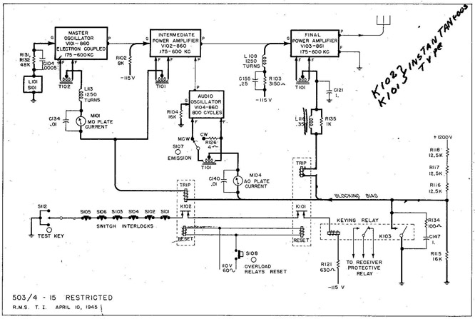
(b) Protective fixed bias on the grids of both amplifier tubes.
(c) DC for the keying relay (K-103) is supplied from the bias generator.
2. OPERATION:
(a) With the TEST KEY (S-112) open, the keying relay (K-103) is not energized, and about 360 volts of positive bias exists on the filament returns of all stages. This corresponds to negative bias on the grids, and is sufficient to block all stages.
(b) When the TEST KEY (S-112) is closed, the keying relay (K-103) is energized. The main contacts short out the blocking bias and connect the filament returns to ground, so all stages operate normally.
(c) When the EMISSION switch (S-107) is in CW position, the AO filament is disconnected and a dummy load R7126 substituted to maintain normal filament supply voltage on the other stages. However, the keying circuit is not changed.
(d) The key click filter (R-134 and C-147) prevents arcing at the keying relay contacts to minimize key clicks.
(e) The key thump filter (R-135 and L-116) delays the plate current build up of the final power amplifier (V-103) enough to prevent excessive RF power surges when the key is first closed.
(f) The auxiliary contacts on the keying relay (K-103) are provided for operating a receiver protective relay if necessary.
(a) HIGH POWER 500 watts over the entire frequency range.
(b) LOW POWER 75 watts, using the 2nd IPA as the final power amplifier. Available only from 2,000 to 9,050 kc because doubling is not permissible in the final stage.