PART ONE
GROUND FORCE PHOTO INTERPRETATION (GENERAL)
CHAPTER 1
THE ARMY PHOTO INTERPRETERSection I. GENERAL
1. Purpose
The purpose of this manual is to provide a pictorial supplement to the basic "Photographic Interpretation Handbook" (TM 30-245), prepared jointly by the Navy, Air Force, and Army, November 1952. Throughout this manual, the joint publication will be referred to as the PI Handbook. This Army supplement will serve as a training aid for instruction in photo interpretation of military activity of primary interest to ground forces. It will be a useful reference for Army photo interpreters.
2. Scope
a. This manual covers the interpretation of major items of military activity normally encountered by Army photo interpreters in the field. It is mainly a series of photo interpretation keys on specific subjects. However, the manual also contains helpful reminders and guides intended to aid the Army photo interpreter in the execution of his duties.
b. The Army photo interpreter will be concerned with many subjects which are not covered in this manual. Air Force and Naval photo interpretation publications will provide the Army photo interpreter with complete studies on industry, electronics, airfields, bridges, railroads, bomb damage assessment, flak analysis, supply depots, waterways, beach obstacles, shore defenses, port and harbor facilities, and other subjects of mutual interest to military services. Army Engineer and Signal Corps publications will provide the Army photo interpreter with complete studies on terrain evaluation, aerial spot coverage, supporting ground photography, photo reproduction, and dissemination procedures.
3. Photo Reconnaissance
There are many sources of military information about the enemy in wartime such as visual reconnaissance, captured documents, prisoners of war, wireless intercepts, spies and agents, and photo reconnaissance. With fast, long-range aircraft, equipped with a multiple large-scale cameras, photo reconnaissance has become one of the most important single sources of information about the enemy. Photo reconnaissance is the most convenient, accurate, and
effective means of gathering quick and reliable information about enemy terrain, forces, and equipment. Photography has a tremendous advantage over visual reconnaissance in that a section of the country becomes frozen for study. It is difficult for the enemy to keep anything secret long as it can be photographed, for despite the enemy's attempt to conceal and camouflage his activities, there remains little he can hide from the prying eye of the air camera.
4. Intelligence From Photo Interpretation
The photo interpreter produces many and varied types of military information suitable for conversion into all the various types of intelligence. In the production of combat and strategic intelligence the photo interpreter furnishes information regarding the enemy defenses, targets, mosaics, beach conditions and silhouettes, flak maps, airfields, industries, terrain, maps and charts, etc. These data may be used in the planning and conduct of both combat and strategic operations. The photo interpreter can also assist in the production of technical intelligence by furnishing interpretation reports of new developments of the enemy.
5. The Aerial Viewpoint
a. Air Photos. Efficiency in interpretation of air photos comes from constant practice. When photographed from above, common objects may, to the untrained observer, appear unidentifiable, but as a result of experience the photo interpreter learns to immediately recognize objects by their characteristics.
b. Maps.
(1) Training in map reading must precede training in photo interpretation since the photo interpreter uses maps constantly in his work. A map is a graphic representation, whereas a photo is an actual picture and as such will show ground features in far more detail. The scale of a map limits the number of conventional signs that can be shown, while such features as paths, hedges, fields, and individual houses are all clearly visible on a photo. However in the dissemination of photo intelligence, a constant reference is made
4
to maps, therefore, the interpreter must be able to correlate photos with maps quickly and accurately.
(2) The photo interpreter is primarily concerned
with photos of enemy territory. It is frequently necessary to use enemy maps or those produced by other countries. The photo interpreter must be familiar with TM 5-248 and FM 30-22.
Section II. RESPONSIBILITIES AND DUTIES
6. Responsibilities
It is the responsibility of each photo interpreter to possess-
a. A full awareness of the characteristics of photos.
b. A thorough understanding of the military organization, tactics, and techniques of the enemy.
c. An equally thorough knowledge of the characteristics of agriculture, industry, transport, living customs, and civic planning of the enemy.
d. An attitude that is positive. Photo interpretation requires a scientific approach. Such qualities as common sense, disciplined study, research, and experience are prerequisites for proficiency. Solutions to all questions are not easily obtainable, but with a positive attitude and a full awareness of his medium, a qualified interpreter can present to the layman a detailed and accurate analysis of enemy activity.
e. An awareness of the necessity for close relationship between the Photo Interpreter (PI); the Order-of-Battle Officer (OB); the Interrogator, Prisoner of War (IPW); the Tactical Liaison Officer (TLO); and the other intelligence personnel in his unit.
f. An awareness of the need for rapid dissemination of photo information through intelligence channels to the using unit for prompt planning or combat action. Timely information saves lives and equipment and wins battles.
7. Specific Duties
a. The specific duties of the interpreter are numerous and may include many or all of the following:
(1) Tactical interpretation.
(2) Strategic interpretation.
(3) Selection of bivouac areas.
(4) Selection of artillery targets.
(5) Selection of routes of approach.
(6) Selection of airfield sites.
(7) Selection of landing areas for assault transports.
(8) Selection of drop zones and objective areas.
(9) Checking friendly camouflage.
(10) Preparation of trafficability reports (roads, bridges, cross country).
(11) Corrections and supplements to maps.
(12) Construction of mosaics.
(13) Terrain analysis.
(14) Verification of information from other intelligence sources.
(15) Briefing of patrols.
b. Each interpreter must be able to disseminate his findings by oral or written reports in such a manner as to be readily understood by the using unit.
Section III. MECHANICS OF INTERPRETATION
8. Steps in Interpretation
There are definite steps in the interpretation of air photographs. The sequence may vary with individuals but in general it is-
a. Orientation of photo with map.
b. Cursory search.
c. Stereoscopic study.
d. Identification and analysis.
e. Report of findings.
9. Marginal Information
Each photo normally contains marginal information such as date, focal length of camera, altitude at which photo was taken, sortie and print numbers, type of photo, and the organization flying the mission. The first and last print of a sortie will usually show geographic coordinates; towns and cities covered by the flight are frequently identified in the marginal data.
10. Orientation
a. Marginal Data. When orienting photographs, the
specific area or locality is often obtained from the marginal data.
b. Shadows. One method of orienting a photo is by shadows of objects on the photo. In the Northern Hemisphere, shadows fall generally north at noon, west of north in the morning, and east of north in the afternoon. In the southern hemisphere, the shadows fall south, southwest, and southeast, at noon, morning, and afternoon respectively. When viewing a single vertical photo, it should be held so that shadows fall toward the reader. With shadows falling away from the reader, features of relief may appear reversed, hills appearing as depressions and valleys appearing to be hills. When interpreting stereopairs, the direction of shadows is of less importance. The effect of relief will then be apparent from stereoscopic depth perception. When studying an oblique, it must be held with the foreground nearest the observer; otherwise, objects will not be in proper perspective relationship with each other.
c. With the Ground. A photo can be oriented with the ground by inspection, in the same manner as a topographic
5
map. If direction on both the photo and ground is known, orientation is simplified. Prominent features on the photo are carefully compared with the terrain. The photo is turned so that all photo features are in proper relation with the corresponding features on the ground.
d. With a Map. A photo can be oriented with a map as with the ground. If north can be established by shadows or by marginal data, it remains only to determine the exact limits of the photo on the map. This is done by selecting prominent features on the photo which also appear on the map. Because maps are drawn with conventional signs, objects may not be shown in true scale or shape, and may also be inaccurately located. Thus care in reading both the photo and the map is necessary.
11. Cursory Search
a. Photo interpretation is, in part, a process of elimination. As the primary interest is in the military installation or object, the interpreter separates the natural features in the photo from the manmade and eliminates the natural. The manmade features are then broken down into two classes, the military and the civilian. Eliminate the civilian and the primary goal, the military, remains. Distinguishing between natural and manmade objects is a simple matter. Contrast the wandering course of a river with the channelled bank of a canal. Nature works without pattern; man works in straight lines, sweeping curves, and angles. Distinguishing between the two classes of manmade objects or installations is more involved. It is based upon the relationship factor of identification. The installation is studied to determine its use. For example, a permanent military installation has certain definite characteristics, such as rifle ranges, motor pools, parade grounds, gates, and fences, which would readily distinguish it from a campus or a spaciously planned urban community. The process of interpretation also involves a certain logical evaluation of area. For example, if the photographs cover the enemy's front line, a search would naturally be made for front line type defenses. Low-lying coastal areas may be expected to have marshes or swamps whereas steep shore lines may not. In industrial analyses, large cities would be expected to have a complex system of manufacturing, transportation, and communication. Smaller towns, however, may be based upon a single phase of industry determined by local raw materials, physical location, or professional qualifications of the people.
b. The possibility of an activity's presence should not be discarded because it is contrary to the expected usage. Aircraft engines can be built in exhausted salt mines; large cannon can be fired from highway or railroad tunnels.
12. Factors of Identification
The five basic factors of identification are the photo interpreter's fundamental aids in recognizing and identifying what is seen on air photos. Every interpretation utilizes these factors either singly or in combination.
a. Size. The relative size of an object may, by inspection, indicate its identity. A one-man foxhole is easily distinguished from a nearby machinegun emplacement even though both are circular in shape. The size of a tank, measured on an air photo, may identify it as light, medium, or heavy.
b. Shape. Objects or installations have characteristic shapes or patterns which simplify identification. An artillery piece positioned with trails spread has a distinctive forked shape. The shape of an antiaircraft battery layout pattern, sited for air defense only, usually circular in shape, is easily distinguished from the inline layout pattern of a field artillery battery.
c. Shadow. Shadows may reveal the silhouette of an object. The shadow cast by a tank may, by the silhouette of the gun barrel, superstructure, and chassis, establish its identity as a specific model.
d. Relative Tone. Tone is the shade of gray (between the extremes of black and white) which an object's image assumes on a black-and-white photo. The difference in tone between the camouflage covering of an object and that of the. surrounding area may indicate the presence of a concealed weapon or installation.
e. Relation to Surrounding Objects or Area. Objects will have one or more associated features or auxiliary installations which may be a clue to identification. An observation post or a command post may betray the location of a hidden coast artillery battery. Special equipment, distinctly shaped vehicles, or buildings, may disclose a guided missile site.
13. Measurements
Size is frequently one of the most important deciding factors in identification and interpretation. Measurement is based on the scale of the air photos and maps used, and the conversion to units of measure expressed in the English or metric system.
a. Scale Computation. The standard expression of scale is the representative fraction (RF). Two formulas are available to determine a photo scale. They are-
(1) RF = f (focal length of the camera) / H ( altitude of camera above ground)
(2) RF = PD (photo distance) / GD (ground distance)
b. Use of Formulas.
(1) Formula RF = f / H To determine the scale of a
photo using this formula, the two elements f and H are extracted from the marginal data. As given, the focal length (f) is usually stated in inches (rarely in millimeters), while the altitude (H) is generally in feet. It is necessary to reduce these values to a common unit of measure. Whether the altitude shown is actual distance above ground level or above mean sea level is not always known. The method of setting altimeters varies among the photo flying units. Whenever possible, stated altitude should be corrected to
6
true altitude for use in formulas. For example, information appearing in the margin of a photo reads (24-30,000). This indicates that the focal length of the camera is 24 inches and the altitude of the aircraft at the time of exposure was 30,000 feet. By substituting in the formula, the following would result:
RF = f / H = 24 inches / 30,000 feet X 12 = 24 / 360,000 = 1/15,000
RF = 1 / 15,000
(2) Formula RF = PD / GD. To determine the scale of a photograph using photo distance and ground distance, two methods can be used:
(a) Comparing the photo with a map. The photo is oriented for direction and location with a map of the same area. Scale lines are established on the photos. The characteristics of scale lines are-they pass through or near the center of the photo; they connect points easily located on the map and the photo; points should be of approximately equal elevation and be equidistant from the photo center. The length of the scale lines on the photo is compared to the same scale lines on the map, multiplied by the map scale denominator. For example, let the photo distance equal 0.627 foot; map distance 0.209 foot; map scale 1:25,000. By substituting in the formula
RF = PD / GD the equation becomes- RF = 0.627' / (0.209' x 25,000) =.0627' / 5225.000' = 1 / 8333' the RF of the photo.
Two or more scale lines are used on a photo in determining several RF's. A final working RF is then obtained by averaging the several denominators.
(b) Comparing the photo with the ground. If the dimensions of an object or the distance between two or more points are known, the scale of the photo can be determined. The photo dimension over the actual dimension of the object will give the scale. By reducing the fraction to one having a numerator of 1, the representative
fraction is obtained. For example, it is known that a bridge visible on an unsealed photo is 124 feet long and 38 feet wide. On the photo, it measures 0.013 foot long and 0.004 foot wide. Therefore-
For general purposes, the scale would be rounded off to 1:9,500. The working RF of 1:9519 is determined as shown in paragraph 13b(2)(9).
c. Scale Size. For intelligence interpretation, photos should have a scale of 1:10,000 or larger to permit accurate detailed work. For mapping purposes, scales of 1:20,000 or smaller, are satisfactory.
d. Interpreters' Scale. The interpreters scale, a transparent plastic device designed to simplify measurement of objects on air photos, is divided into tenths, hundredths, and thousandths of a foot. After determining the RF of a photo, as explained previously, merely place the scale over the distance or object to be measured and read the scale to the nearest thousandth. Multiply this reading by the denominator of the RF. The result is expressed in feet. There are definite factors such as quality of film, density of emulsion, distortion, variations in altitude, and human fallacies in taking and producing photographs, which affect the accuracy of measurement on air photos. However, on the average, measurements are approximately 95 percent correct, when United States films, cameras, and photographic equipment are used.
e. Plotting. For plotting purposes it is necessary to know the size of the area a photo covers on a map. The formula for determining these measurements is as follows:
Size of plot = (Denominator of photo RF X photo size) / Denominator of map RF
Size of plot = 1.8 inches x 3.6 inches. (These measurements can be used for setting on the plotting template.)
f. Units of Measure. Appendix B to the PI Handbook contains detailed mensural conversion tables for use by all photo interpreters. The Army photo interpreter will find the following table adequate for all normal needs:
Table of Equivalents
1 millimeter (mm)
= 0.001 meter
= 0.0394 inch
= 0.0033 foot.
1 centimeter (cm)
=0.01 meter
=0.3937 inch
=0.0328 foot.
1 decimeter (dm)
=0.1 meter
= 3.9370 inches
= 0.3281 foot.
1 meter (m)
=1,000 mm
=100 cm
=10 dm.
1 meter (m)
=39.37 inches
= 3.28083 feet
=1.09361 yards.
1 kilometer (km)
=1,000 meters
=100,000 cm
=1,000,000 mm.
1 kilometer (km)
= 3,281 feet
=1,094 yards
= 0.62137 mile.
1 inch
= 0.0254 meter
= 2.54 cm
1 foot
= 0.3048 meter
= 30.48 cm
1 yard
=0.9144 meter
=91.44 cm
1 mile
=1,609.35 meters
=1.609 km
1 mile
=1,760 yards
= 5,280 feet
= 63,360 inches.
7
14. Collection of Data
The reference library of the Army photo interpreter should include every available publication that will assist in the correct interpretation of what is seen on aerial photographs of critical areas. The Army, Air Force, and Navy separately and jointly provide photo-interpretation studies of vital mutual importance. Ground checks and profile photographs of activity previously interpreted from aerial photos of overrun hostile terrain, will provide the Army photo interpreter with verified data, which will expedite photo interpretation of enemy military activity in a known zone of action. This data, consisting of air and ground photographs, sketches, diagrams, and detailed descriptions, should be indexed and filed by subject matter and geographic location. The Army photo interpreter must, by necessity, be a collector, and therefore
constantly alert in the collection of reference photographs and material which build up his library. No single photo interpreter can hope to know all there is to know about military ground, air, or naval activity, but each Army, Air, and Navy photo interpreter can be an expert in his own field and a valued consultant to his colleagues in the other services.
15. New Developments
The Army photo interpreter should, by reading and research, keep abreast of any and all changes, improvements, and new techniques which affect the taking, reproduction, and interpretation of aerial photographs. Air Force, Navy, and Army agencies have a mutual interest in any development which facilitates the collection, through aerial photographs, of intelligence which aids the destruction or neutralization of enemy power.
8
CHAPTER 2 THE ARMY PHOTO INTERPRETATION SECTIONSection I. GENERAL
16. Introduction
This chapter covers the operation of a photo interpretation section in the field.
17. Procedure
Photo-interpretation sections, at all levels of command, use the same basic operational methods. Common procedures include office organization, maintenance of PI records, planning, photo requesting, receiving and checking information from other sources, and mission processing.
Section II. ADMINISTRATIVE
18. Office Organization
The photo-interpretation (PI) section should have a large working area in which to spread photos, plot, construct mosaics, display overlays, and store photos.
19. Site
The location of the PI section should be in or near the operations area of the intelligence section. The PI Officer must work in close proximity to the Order-of-Battle Officer ( OB) at division and corps, the Counter Mortar Intelligence Officer ( CMIO) at division artillery (Div Arty) , and the Counter Battery Intelligence Officer ( CBIO) at corps artillery. The Army PI section of the Joint Air Photo Center (JAPC) is located near the reconnaissance field of the Tactical Air Force (TAF).
20. Special Equipment
In addition to T/O & E equipment, the PI section should have large map boards and work tables, storage cabinets and shelves for photos and maps, a reference library, miscellaneous files, a looseleaf notebook or card case for the mission results or target file, and card cases for photo intelligence data cards. The work tables can be constructed from 4' x 8' plywood panels obtained from engineer supply; map boards are cut from plywood to fit maps or mosaics; cabinets, shelves, map and overlay containers can be constructed from wooden "C" ration boxes. Overlays can be bound together at one end with wooden strips and hung in racks or on nails. Small card cases, if not issued, may be constructed from heavy cardboard.
Section III. RECORDS
21. General
Photo records consist of photo plots, mission records, reports, overlays, mosaics, and miscellaneous records of the activities of the sections.
22. Plots
Each photo mission must be plotted so that the area can be readily located on a map. Plots are also used to locate individual photos and as an index of areas photographed. At division and corps, PI sections normally plot at a scale of 1:50,000 or 1:25,000, the larger scale being preferable. Army PI sections normally plot at the scale of the operational map of the field army. The larger the map scale the more accurate and rapid will be the plotting. Plotting is described in detail in section V, chapter 3, of the PI Handbook. A cover trace or master plot of all missions received should be maintained at the scale used by the receiving
unit. The outline of the area covered by each mission should be shown in the same color. The legend includes mission,number, date, focal length, altitude, and quality of photography. Field plots from the JAPC which accompany the photos are frequently used in lieu of a cover trace.
23. Mission Records
These records normally will include photo intelligence data cards, an air photo record book, and a mission result or target file.
a. Photo Intelligence Data Card. The reconnaissance technical squadron will normally prepare this card. Section I, chapter 5, of the PI Handbook describes the card. By adding a file number, receiving units can use the card as both a sortie and geographic index of the photography. If these cards are not received, a similar card may be improvised.
9
b. Air Photo Record Book. A chronological log should be maintained of all sorties (missions) received, showing unit file number, mission number, print numbers, date received, date and type of report made, distribution of photos, and date of destruction of photos.
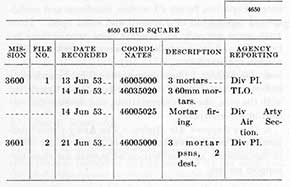
c. Mission Result or Target File. Preparation of a card or page for each map grid square covering the zone of action will simplify the recording of enemy activity detected in the area or reported by other agencies. A suggested tabbed card form is as follows ( for bound pages tabs may be indexed on the side):
24. Reports
Flash, immediate, mission review, summary, detailed, and special reports are described in section I, chapter 5, of the PI Handbook.
25. Overlays
Overlays tend to become cluttered with information and annotations, making them difficult to read and understand. This can be avoided by the use of separate overlays. Defense, logistics and communications, and information overlays are the three most commonly used. The overlays are normally attached to map sheets used by the section. The Div Arty PI section need only to maintain an informational overlay, since the Div Arty S-2 and the CMIO maintain target overlays on which are posted PI findings.
a. Defense Overlay. Enemy defenses detected on air photos are annotated on this overlay with the correct symbols (FM 21-30). To avoid jammed annotations, the defense overlay can be divided into two sections, one showing artillery and mortars and the other showing fortifications and other defenses. The corps artillery PI section normally shows only hostile artillery or special targets on the defense overlay.
b. Logistics and Communications Overlay. Supply installations, personnel and vehicle shelters, bivouac areas, roadblocks, and other activity not shown on the defense
overlay, are annotated on the logistics and communications overlay.
c. Information Overlay. Information received from other sources can be posted on this overlay until confirmed or denied by the PI. If confirmed, the item is transferred to one of the other overlays; if erroneous, the item is erased. Information to be posted can be obtained from the following reports:IPW, CIC, line crosser, patrol, air observer, ground observer, sound, flash, radar, shell, mortar, and PI flash and immediate reports.
26. Mosaics
a. Air photo mosaics of each zone of responsibility furnish a bird's-eye view of the terrain in each unit's area. If desired, they may be prepared and distributed to units including battalion. The mosaics are easily assembled from available photography, preferably of a small scale to reduce size. Map grids, superimposed on the mosaic, facilitate cross-reference from photo to map to ground. When used in lieu of an overlay, grease-pencil annotations on the mosaic present a quick picture of up-to-date activity of prime interest to the commanding general, staff officers, and regimental and battalion commanders of the unit served by the Army photo interpreter.
b. A mosaic also serves the following purposes:
(1) Affords the photo interpreter an overall view of the area with which he is concerned.
(2) Facilities verbal orientation, planning, and command briefings.
(3) Facilitates briefing and debriefing of pilots and observers.
(4) Supplements maps.
(5) Substitutes for overlays.
(6) Facilitates rapid orientation of spot, pinpoint, or other photography.
(7) Facilitates location of terrain features.
c. Panoramic mosaics can be prepared from ground photos taken from observation posts by ground photographers. Ranges and azimuths to key terrain features, check points, and artillery concentrations are annotated on the mosaic. The fields of observation are annotated on an accompanying map sheet. At fire direction centers (FDC) the panoramic mosaics are used to coordinate observation. At observation posts (OP) they are used for rapid computation of firing data and in orienting new observers.
27. Miscellaneous Records
Copies of reports prepared by the unit, reports from higher units, photo mission requests, correspondence, and reprint requests should be filed systematically for easy reference. The reprint request record should show unit requesting prints, date of request, mission and photo numbers, date of receipt, and date of dissemination.
10
Section IV. PLANNING
28. Strategic
Photo interpretation for long-range planning is normally accomplished by interpreters at the field army, army group, or the central interpretation unit of theater headquarters. This interpretation may include photo studies of railroad marshaling yards, rear area supply depots, industries, cities, distant bridges, dams, or key areas.
29. Tactical
a. Future Operations. Photo interpretation for operational planning is usually initiated at JAPC and completed by PI sections down to division level. Defense and other overlays can be overprinted on maps by the field army engineer topographic battalion prior to the actual operation. Complete PI studies with overlays, overprinted maps, mosaics, and annotated photos can be prepared prior to the execution of an operation. If engineer photo interpreters are not available, unit interpreters may have to prepare road and bridge reports prior to the operation. Div Arty PI sections can provide forward observers, attached to attacking tank or infantry units, with annotated photos showing targets or threats in the route of advance.
b. Map Supplement. Photo studies are often made prior to an operation to supplement map reconnaissance in the location of future command posts, artillery battery positions, bivouac areas, traffickable routes (road, bridge, cross-country, stream crossings) , observation posts, and cover and concealment.
c. Liaison. The exploitation of maximum PI effort is materially assisted by frequent visits to higher, lower, and adjacent units. Plans, common needs, problems, differences of opinion, future PI studies, timeliness and usefulness of reports can be discussed and acted upon. These visits serve not only to maintain close relationships between PI and other intelligence personnel, but also with combat commanders.
d. Air Flights. Photo interpreters should participate in frequent aerial flights in order to familiarize themselves with the area, check interpretations, and develop the vertical or air viewpoint.
e. Close Support Air Strikes. The Army photo interpreter can be of valuable assistance to the G3 air officer in the selection and verification of targets for close air-support strikes.
Section V. PHOTO REQUESTS
30. Types of Cover
Basic, frontline, special, and mapping photography are the usual types of photo cover used by the photo interpreter. Basic and frontline cover is usually distributed to corps and division by higher headquarters. The army photo interpreter will not normally be concerned with mapping photography, but he is concerned with special cover when basic and frontline cover fail to meet his requirements. Special cover includes the following:
a. Block. Specific geographic area plotted and indexed to simplify reconnaissance photography.
b. Pinpoint or Spot. One or more photos of a specific object, target, or small critical area where large scale is necessary.
c. Route or Strip. Photography of long narrow areas such as roads, railroads, valleys, ridges, rivers, and beaches.
31. Air Force Photography
The Army photo interpreter assists the G2 Air in preparing and consolidating requests for Air Force photography (see app. II). Careful planning will save time, effort, planes, photographic supplies, and overburdening of facilities. One mission may be able to provide the requirements of several requests. Photos on hand or reprints may provide the necessary photography and save requesting further missions. An average PI section can interpret and report approximately 200 prints a working day. A desirable large scale for better definition must
be balanced against the resulting large number of prints. A mission may cover an area 10 x 10 miles, or 100 square miles. Nine-inch by 9-inch photography with 60 percent overlap in the direction of flight, and 50 percent side lap would result in 200 prints at a scale of 1:10,000; 400 prints at a scale of 1:7,500; 800 prints at a scale of 1:5,000; and 2,000 prints at a scale of 1:2,500. Large scale photography must be limited to selected targets or small critical areas.
32. Organic Photography
The photo interpreter can fill many of his requests with photos taken from the aircraft of the army unit's light aviation section, by organic photographers. If possible, cameras should be mounted in at least one of the planes and a pilot and photographer assigned to work as a team. As the personnel, planes, and laboratory equipment are located in the vicinity of the headquarters, the pilot and photographer can be briefed, the mission flown, and the prints developed and reproduced in a minimum of time. They are interpreted in the same manner as Air Force photography.
33. Reprints
Reprints of those portions of a mission that are required by subordinate units may be ordered from the JAPC through the JOC. If needed immediately, the original annotated prints are distributed and the reprints retained when received.
11
Section VI. RECEIVING AND CHECKING INFORMATION
34. Coordination
The senior Photo Interpretation Officer must insure that information from other sources reaches his section rapidly. Close liaison with the G2 Operations Officer and the other intelligence specialists in the G2 section will facilitate this flow of information. In artillery headquarters all information is channeled through the S2. At the JAPC the senior Ground Liaison Officer or other designated officer may coordinate the flow of information from other sources.
35. Method
When the information is received, it is checked against the section's records to determine if it is new or if it confirms previous information. New items are plotted on the informational overlay and checked on current photography. Any items not confirmed are left for checking on the next photo mission.
Section VII. MISSION HANDLING
36. General
A photo mission is handled in a production line manner. It is logged, plotted, interpreted, and its items located and reported. The records are brought up to date and the photos filed.
37. Photo Scanning
Film is unloaded at the JAPC and processed by the Air Force in the most expeditious manner. In special missions the wet negatives may be scanned by the pilot and the photo interpreter to determine if the sortie covers the correct area, is suitable for the purpose intended, and to detect any flash, items. These items may be annotated on the negatives to enable rapid location on the finished prints.
38. Logging and Preparation
The senior noncommissioned officer of the section or the army operations sergeant at the JAPC receives and logs the mission in the air photo book. The field plot is hastily checked to eliminate photos or missions that fall outside the unit's zone of responsibility. A mission flown in several runs may be divided into individual runs or strips for plotting and interpreting by several interpreters. These parallel strips side lap from 30 percent to 50 percent. The side lap from the first run is crossed out with grease pencil on the photos of the second run; the side lap from the second is crossed out on photos of the third run. This process is continued until all side lap area is eliminated. Marking out the side lap insures that the same area in a mission is not interpreted twice.
39. Plotting
The best draftsman or draftsmen at sections other than the JAPC should be permanently assigned as plotters. Plotting is started on an acetate-covered map mounted at the end of one of the work tables. While one run is being plotted the remaining runs are being interpreted. If there are more interpreters than runs, the plotter starts on the opposite end of one of the runs and plots until he meets the interpreter. They then trade photos and continue. At JAPC, plotting is normally done by a separate section using a duplicate copy of the mission.
40. Interpretation
a. The interpreters annotate their findings on the photos with grease pencils. After each interpreter finishes his run he starts another, assists another interpreter, or assists the plotter in the location of map coordinates of the annotated items.
b. Division artillery has fewer photo interpreters and should not attempt to duplicate the efforts of the division PI section. While waiting for flash reports and completed interpretations from division, Div Arty interpreters should use the duplicate copy of the mission to confirm items on the informational overlay.
41. Grid Reference
Interpreted items should be accurately located on a map by using a coordinate scale. The location should then be annotated on the photo with four place grid reference (10001000). Experience dictates whether it is quicker for the interpreter to record the grid reference of an item as he finds it, or for the plotter and otherwise unoccupied interpreters to record the grid reference as the plotting of the backlog of interpreted photos is completed. Items are usually located by inspection. Photo restitution and rectification methods or special devices may permit greater accuracy in map grid location when pinpoint targets are being located.
42. Cross-Checks
Interpreted items should be checked on defense overlays and records of the PI section to determine their newness, and against items on the informational overlay for confirmation, transfer, or erasure. This checking can be done by the senior noncommissioned officer or by the individual interpreters. Experienced interpreters familiar with the area will cross-check automatically as they interpret.
43. Preparation of Reports
a. Flash, and immediate reports are completed and disseminated before the mission review, special, detailed, or summary reports are begun. At all echelons flash items are reported to the G2 or S2, then phoned or dispatched to lower units. The information will include photo number, description of the target, photo grid coordinates, and map grid coordinates.
12
b. As soon as a backlog of completely interpreted, located, and cross-checked photos is built up, the mission review report is started. If this is to be included as a section of a Periodic Intelligence Report (PIR), a stencil can be cut at this time. If not, a sufficient number of typed copies are prepared.
44. Artillery Targets
Lucrative, active items, suitable for fire missions, are prepared as targets by the artillery PI section. The activity is determined by a check of the informational overlay, the records of the CMIO, CBIO, or by a special air check.
a. Priority.
(1) Div Arty.
(a) Enemy artillery pieces and mortars. (b) Fortifications and other defenses. (c) Logistic, personnel, communication, and short range harassing and interdiction targets.
(2) Corps Arty.
(a) Long-range enemy artillery batteries. (b) Destruction of long-range special targets such
as bridges, railroad marshaling yards, and others beyond the range of division artillery. (c) Longe-range harassing and interdiction targets.
b. Target Folders. An excellent means of recording target information for use by air observers is a target folder. On one side of the folder is placed the annotated photo, photos, or mosaic, while on the other side is the applicable portion of a map, covered with acetate, on which the photos are plotted and the targets annotated. A section for remarks should be included on the folder to enable the observer to record the results of his observation.
45. Photo-Print Library
After the records are brought up to date, the annotated photos are placed in the photo boxes. The mission file number is placed on the outside face of the boxes. The boxes are then stored in the photo cabinet. Only current missions should be stored in the photo-print library. When the photos are no longer useful they are destroyed in accordance with AR 380-5.
13
PART TWO
INTERPRETATION OF MILITARY ACTIVITY
CHAPTER 3
ANTIMECHANIZED DEFENSESSection I. GENERAL
46. Active Defense
The means for protection against mechanized attack are active and passive. The active means include tanks, antitank guns, smoke, chemicals, artillery, combat aviation, armored vehicles, grenades, rockets, recoilless rifles, and small arms. Usually active and passive means are employed in combination, the freedom of maneuver of mechanized vehicles being limited by the passive means and their destruction accomplished by the active. Thus antimechanized weapons may be expected in the vicinity of natural or artificial obstacles or where artificial obstacles would normally be placed. Antitank weapons normally depend upon fire by direct laying and therefore must have good fields of fire at ranges up to 1,000 yards. They are often found covering long, straight stretches of road, defiles, and in sites covering stretches of antitank ditch, minefields, or other obstacles.
47. Passive Defense
Obstacles such as mines, tank traps, roadblocks, ditches, barricades, and demolitions will be located at defiles or
where avenues of approach are canalized. These include cuts and fills, bridges across unfordable streams, and roads through heavy woods and swamps or other unsuitable terrain, especially where it is difficult or impossible for the vehicles to detour. Artificial obstacles such as antitank ditches, dragons' teeth, antitank walls, antitank blocks, and minefields cover more open terrain and will usually be joined with natural obstacles (slopes of steep hills or mountains, bodies of deep water, marshes, heavy woods, and rocky ground).
48. Protection of Obstacles
An obstacle is of full value only when protected by fire. The interpreter should attempt to locate the covering force. Figure 11 shows passive defense combined with active. The antitank defense line is interpreted as follows:Circle A, Antitank gun in tank turret mounting (see fig. 17 for ground view); Circle B, Antitank gun turrets mounted on large underground shelters (see figs. 13, 14, and 15 for ground views and plan of shelter); Circle C, Antitank ditch (see figs. 10 and 12 for ground view); Circle D, Light AA gun; Circle E, Roadblock.
Section II. ANTITANK DITCHES
49. General Description
Because of its width and length and its distinctive marring of the earth's surface, the antitank ditch is one military feature which is easily discernible on an aerial photograph. Ditches are laid out so as to canalize tanks toward antitank guns, minefields, or impassible natural obstacles, and to delay their progress.
50. Identification Characteristics and Techniques
a. The antitank ditch will usually appear as a dark, fairly straight line with bordering light-toned shoulders. The light tone will vary with the age of the construction, degree of care in removing spoil, and growth of vegetation over the shoulder or parapet areas.
b. The presence of antitank ditches is often a quick clue to other military activity in the area. In permanent defensive areas, pillboxes or casemates are usually located
at angles to the traverse in order to fire along the trench (see fig. 12).
c. Antitank ditches are constructed by manual digging, blasting, or mechanical excavator. Most construction is along straight lines with the straight portions joined by angular turns. However, the pit-type ditch, shown in figure 19, presents an irregular chain-link pattern. The utilization of dry riverbeds, intermittent streambeds, and irrigation ditches in the construction of antitank ditches presents an irregular or ragged line as shown in figures 38 and 46.
d. The size of the tanks being guarded against usually dictates the width and depth of antitank ditches. A simple rule for considering widths is "half the length of the tank plus 1 foot." Ditches dug deeper than the highest part of the tank tread will generally delay or trap the tank. Approximate figures for the required widths are
14
as follows:light tanks, 6 to 8 feet; medium tanks, 8 to 12 feet; and heavy tanks, over 12 feet. Depths vary from 5 to 15 feet in most cases, but ditches deeper than 15 feet are not uncommon. Flooding ditches with water adds to the effectiveness of the obstacle against tanks and personnel.
51. Photo Examples
Figures 1 to 52, inclusive, is a series of studies or keys on antitank ditch defenses. Examples include World War II and Korean combat photography. It is interesting to note that figure 18 shows a pit-type antitank ditch used by the Russians against the Germans in World War
II and figure 19 shows a similar pattern used in North Korea, 1951-52.
52. Checklist for Reporting Antitank Ditches
a. Location.
b. Length, width, and depth.
c. Route or area protected.
d. Possible bypasses.
e. Covering defenses ( antitank guns, rocket launcher positions, other artillery, casemates, pillboxes).
f. Other obstacles (natural or constructed) used in conjunction with ditch.
g. Alignment.
Section III. DRAGONS' TEETH
53. General Description
The vertical aerial photograph will normally show dragons' teeth in long, broad, checkered bands, as seen in figure 56. As shown in figures 53 to 55, the teeth are made of concrete, are generally pyramidal in shape, and vary in size.
54. Identification Characteristics and Techniques
a. Dragons' teeth are laid in rows; two or more staggered rows forming a belt.
b. The interval from apex to apex between adjacent teeth is normally about 6 feet.
c. The distance between rows will be approximately 9 feet.
d. Sharp angles characterize changes in direction of the belt.
e. The light tone shadow and symmetrical arrangement of the teeth form a distinctive pattern on the earth's surface.
55. Photo Examples
Figures 53 to 68.
56. Checklist for Reporting Dragons' Teeth
a. Location.
b. Length and width of belt.
c. Number of rows.
d. Distance between rows.
e. Height, width, and thickness.
f. Alignment of rows (staggered, interval between teeth).
g. Route or area protected.
h. Possible bypasses.
i. Covering defenses (antitank guns, rocket launcher positions, other artillery casemates, pillboxes).
j. Other obstacles (natural or constructed) used in conjunction with dragons' teeth.
Section IV. ANTITANK WALLS
57. General Description
An antitank wall is a continuous obstruction which may be composed of concrete, stones, timber, logs, coral or any other material available for use. The wall is built above the level of the ground and normally will cast a distinctive, regular shadow. The term Antilanding Wall is used to describe this type of obstacle when built along beaches. Walls are normally solid but may be segmented to permit the use of small arms and automatic weapons from behind them.
58. Identification Characteristics and Techniques
a. Continuity, shape, and location are primary factors in the identification of antitank walls.
b. Walls may be from 4 to 8 feet high and from 3 to 5 feet thick.
c. Regularity, length, and width of shadow are important factors in the identification of walls.
d. Barbed-wire entanglements are generally strung along the top of solid antitank walls and in front of the openings in the segmented ones to hinder and delay personnel.
59. Photo Examples
Figures 69 to 78. Figure 74 represents antilanding defenses in Northern Italy off the Gulf of Genoa, 1943-44. The wall is continuous for over a mile. "A" shows three camouflaged German casemates; "B" shows four typical pillboxes built into the wall; "C" shows Italian casemates and pillboxes, the largest being 47 feet across; "D" shows crew shelters under construction "E" shows concrete monoliths (blocks) of a type commonly used to obstruct streams and river beds; "F" shows an antitank ditch.
60. Checklist for Reporting Antitank Walls
a. Location.
15
b. Length, width, and height.
c. Route or area protected.
d. Possible bypasses.
e. Covering defenses (casemates, pillboxes, etc.).
f. Other obstacles (natural or constructed) used in conjunction with antitank wall.
Section V. ANTITANK BLOCKS
61. General Description
Antitank blocks are square or rectangular in shape. They are usually made of reinforced concrete but may be constructed of any available material. On aerial photographs they normally present an appearance of short stretches of straight linked heads.
62. Identification Characteristics and Techniques
a. Continuity, shape, and location are primary factors in identification.
b. Blocks are cubes approximately 5 feet square or rectangles 5 by 10 feet, spaced 5 to 6 feet apart.
c. Blocks are generally set in single or double rows between other artificial or natural obstacles in an antitank defense line.
d. Shallow rivers and streambeds in antitank defense lines are generally closed with this type of block.
e. The straight line, beadlike pattern is a distinctive recognition feature. Normally only comparatively short stretches of this type of obstacle are constructed.
63. Photo Examples
Figures 79 to 88.
64. Checklist for Reporting Antitank Blocks
a. Location.
b. Length and width of belt.
c. Number of rows.
d. Distance between rows.
e. Height, width, and thickness of blocks.
f. Interval between blocks.
g. Possible bypasses.
h. Covering defenses (antitank guns, casemates, pillboxes, etc.).
Section VI. ANTITANK TRAPS
65. General Description
The antitank trap does not fit any standard description and the imagination and ingenuity of the interpreter must equal that of the trap maker. Open pits in roads and defiled areas are easily discernible on aerial photographs since they are simply short antitank ditches. However, concealed underroad tank traps (pits covered over) , prepared artillery shell traps, fougasse traps, and other prepared tank trapping installations are extremely difficult to detect on aerial photos.
66. Identification Characteristics and Techniques
a. Open pits or trenches are readily discernible particularly when dug across roads.
b. Covered road traps may be indicated by changes in the tone of portions of the road. Road repairs, particularly after bombings, will also show tone changes, but these will normally be less regular. Tank traps will be as long as a tank and at least as wide. The change in tone of the road above a suspected underroad trap will be rectangular in shape.
c. Points to which tanks are canalized and through which they must pass may be trapped. Through other intelligence agencies, the interpreter should be able to determine the types of trapping installations that may be used by the hostile force. Experience may indicate that the hostile force will place fougasse arrangements in the side of a cliff or hill near which tanks must pass. Logs, trees, or branches on a road over which a tank must pass may be triggers for prepared artillery shell or other demolitioned traps. Thus spoil scars on the side of a hill or objects noted on a road may be clues which the interpreter can tie in with patterns previously set by the hostile force.
67. Photo Examples
Figures 89 to 96.
68. Checklist for Reporting Antiank Traps
a. Location.
b. Type (covered, uncovered).
c. Length, width, and depth.
d. Route or area protected.
e. Possible bypasses.
f. Covering defenses.
Section VII. ROADBLOCKS
69. General Description
Despite the good cross-country mobility of tanks and other tracked vehicles, modern armored warfare is largely dependent on roads for rapid movement. Any obstacle across a road that will cause a military vehicle to stop,
slow down, or detour may be called a roadblock. Roadblocks can be used to physically stop vehicles or to control their movement on roads. Roadblocks vary in construction from massive obstacles built of concrete, timber, steel, or logs, to a single strand of wire across a road.
16
70. Identification Characteristics and Techniques
a. Roadblocks normally will be sited so as to form a part of a line of artificial or natural obstacles.
b. Solid blocks across a road normally will throw sharp regular shadows and change the color tone of the road at that point.
c. Staggered blocks normally will project into the road at set distances in order to force vehicles to slow down.
d. Blocks set opposite to each other across the road may project on to the road or, in other instances, appear as massive gatepost structures along its sides.
e. Felled trees, vehicle hulks, or pieces of cloth strung on wire or rope across a road, may throw irregular shadows or appear as breaks in the road.
f. Roadblocks often will be defended by personnel and weapons. Foxholes and gun emplacements may offer clues.
71. Photo Examples
Figures 97 to 121.
72. Checklist for Reporting Roadblocks
a. Location.
b. Type.
c. Length, width, and height.
d. Construction material.
e. Route or area protected.
f. Possible bypasses.
g. Covering defenses.
Section VIII. MINEFIELDS
73. General Description
The antitank mine is one of the most effective artificial antitank obstacles. Unlike other antitank obstacles, mines are not easily detected on aerial photographs. They are normally buried underground, and, if reasonable care is used, there is little evidence left after the mines are laid. The enemy may sow mines in broad defensive belts, overlapping sections or panels, or short narrow belts. Small groups are used to block beach exits, roads, railroads, bridges, abutments, fords, river banks, gaps between houses, and other defiles. They may also be laid on position to cover withdrawal or buried in the shoulders and ruts of roads. Minefields planted to prescribed patterns are the easiest to detect because of the uniformity of spoil marks, the bands and tufts of differential growth, spots of differential precipitation, and the borders of barbed wire that normally fence in a field.
74. Identification Characteristics and Techniques
a. The interpretation of minefields requires the following:
(1) Adequate large-scale photo coverage at least bimonthly over the entire front.
(2) Favorable background.
(3) Favorable siting.
(4) Intelligence from other sources, whenever possible.
b. Experience shows that photo cover is necessary at least bimonthly because minefields are detected by spoil patterns left when the mines have been laid. When the spoil disappears, as it will with normal growth of vegetation, rainfall and weathering, nothing remains visible save the normal associated features. The spoil marks usually appear as light dots uniformly spaced.
c. Background is important. Mines sown in sandy, arid, or rock country may never be seen due to blending of tone, halation, or broken background.
d. Siting is very important. Mines sown in open country normally will betray some indication of a field, but
when sited in culverts, shoulders of a road, or other sheltered positions, they normally will not be seen.
e. Intelligence from other sources is invaluable if handled correctly. A lead from another source may tie up with associated features of a suspected minefield although the mines in that field are not themselves visible.
f. The following are some of the normal associated features which may aid in the identification of a minefield:
(1) Barbed wire aprons, either on both sides of a minefield in stable defensive zones or on the home side in tactical zones.
(2) Light-toned spoil lines left by the construction of the wire aprons or fences.
(3) Differential growth in the mined and wired areas as compared to the vegetation in the bordering areas.
(4) Patrol or egress paths through a minefield will normally be visible at light-toned scars. These are caused by concentrations of tracks passing straight through the limit of the field and fanning out again in all directions.
(5) The location of defensive positions without apparent antitank defense in country favorable to armored attack.
(6) Blown mines, craters, or blown-up vehicles on the edge of the minefield.
(7) Sod-covered mines often may be detected as uniformly spaced dark dots caused by the healthier growth of the transplanted sod as compared to that in the surrounding area.
(8) The cultivation of land adjacent to a mined area will, in most cases, run at different angles to the mine patterns.
75. Photo Examples
Figures 122 to 157.
76. Checklist for Reporting Minefields
a. Location.
b. Length and width of belt or field.
17
c. Number of rows in each section.
d. Distance between rows.
e. Spacing and alignment of mines (staggered, interval between mines).
f. Location of lanes or gaps in fields.
g. Old, new, or addition to existing field.
h. Route or area protected.
i. Possible bypasses.
j. Covering defenses (automatic weapons, antitank guns, etc.).
k. Other obstacles used in conjunction with minefields or belts (tactical wire, natural, other).
Section IX. ANTITANK GUNS
77. General Description
Antitank guns, because of their low silhouette, small size, mobility, and ease of camouflage, are very difficult to find on aerial photos, unless emplaced in open terrain. The antitank gun is a flat trajectory, high muzzle velocity weapon firing an armor-piercing shell. To fulfill its role, the gun must engage the target at close range in order to insure a kill with its opening rounds. Concealment and camouflage therefore are given much attention and this makes identification difficult from the PI point of view. Guns are organized in units but generally operate singly or in pairs. They are positioned to cover roads, minefields, tank obstacles, defiles, antitank ditches, and open areas suitable for mechanized attack. In forward areas they cover the possible avenues of approach of armored vehicles and support antitank obstacles. Emplacements are normal in stabilized positions, but often the guns are positioned in brush and tree shadows. A field of fire is cleared to the front and flanks. The gun position usually is surrounded by foxholes or slit trenches for the protection of the crew and for storage of ammunition.
78. Identification Characteristics and Techniques
a. Ground information may enable the photo interpreter to limit his area of search, but even then the indications of an antitank gun may be so slight as to escape detection. A knowledge of enemy antitank tactics gained through personal experience or the experience of others will be invaluable to the interpreter in searching likely areas.
b. In fortified lines, antitank guns usually are sited on or close to a line of artificial antitank obstacles (antitank ditches, walls, dragons' teeth, and road blocks). The guns may be found in casements, turrets, open emplacements, or hasty unprepared positions.
c. In a field defense line, the guns are sited to cover the gaps and roads through the artificial and natural obstacles.
d. Because of their flat trajectory and comparatively short effective range, antitank guns seldom, if ever, will fire from a defiladed position. Concealment rather than cover is used to protect the guns.
e. Suspected antitank gun positions in high brush and trees often may be confirmed by the presence of foxholes and slit trenches dug in the open in the vicinity of the gun. Fear of tree bursts often will force the crew to dig
their slit trenches in the open. Unless carefully camouflaged, spoil from the digging will give away the position.
f. Open emplacements can be distinguished by a large ramp entrance on one side and two small bays in the perimeter wall. The wide entrance is for ease of moving the gun in and out of the emplacement. The bays serve as ammunition and personnel shelters. Many emplacements are fan-shaped.
g. Towed antitank guns may be positioned in emplacements that are fan-shaped, oval, octagonal, square, rectangular, or circular, but since the guns are mobile, one side of the emplacement must be wide enough to permit entrance and egress of the wheeled gun.
h. Self-propelled antitank guns generally are positioned in rectangular emplacements with a wide opening in the rear for entrance and egress of the prime mover.
i. Fixed antitank guns in stable defense zones usually are positioned in open concrete emplacements, steel turrets, casemates, or specially constructed positions. Antitank obstacles such as antitank ditches, dragon's teeth, and walls are not difficult to detect on aerial photographs. The photo interpreter, having found the obstacles, must bear in mind that these obstacles are not formidable in themselves. Their entire success depends on the antitank guns covering them. It is vital, therefore, for the interpreter to find as many of the guns as possible.
j. Inner diameters of antitank gun emplacements vary from 10 to 15 feet for light guns and from 16 to 22 feet for heavy guns.
79. Photo Examples
Figures 158 to 213 are examples of antitank guns and their emplacements. Since antitank tactics, like many things military, are subject to change, the photo interpreter must be alert to any new tactics, methods, or techniques that the enemy may use, and be prepared to change his detection methods accordingly.
80. Checklist for Reporting Antitank Guns
a. Location.
b. Number of guns.
c. Classification of weapons.
d. Type of position or emplacement.
e. Field of fire.
f. Route or area protected.
Pages of Figures Listed by First Figure on Each Page
a. Early antiaircraft defense in World War I consisted of rifle and machinegun fire directed at low flying airplanes. Antiaircraft defense is now composed of a complex array of weapons and equipment some of which are listed below:
(1) Antiaircraft guns-light, medium, and heavy; trailed, self-propelled, mounted on railway cars, emplaced in semipermanent positions.
(2) Automatic antiaircraft machineguns.
(3) Fire control equipment.
(4) Generators to run the electrical systems connected with antiaircraft fire control equipment, searchlights, radar, and sound locators.
(5) Searchlights.
(6) Directors or predictors for searchlight control.
(7) Sound locators.
(8) Barrage balloons.
(9) Pursuit or fighter planes.
(10) Radar.
(11) Parachute antiaircraft shells.
(12) Antiaircraft rocket projectors.
(13) Air warning systems.
(14) Guided missiles.
b. The Chinese Communist Army and the North Korean Peoples Army added another type of weapon (see sketch fig. 339). A USAF pilot reported the use of strafing traps by the CCF and the NKPA in the vicinity
of good air targets. These consisted of a pile of bricks which, when set off by dynamite or other demolitions, flew into the air to a height of 1,000 to 5,000 feet, in the path of low flying aircraft. This improvisation served as an object lesson to the photo interpreter, emphasizing that part of his task is keeping abreast of enemy developments in tactics, techniques and weapons.
82. Location
a. In the combat zone, antiaircraft defenses will be found protecting beachheads, bivouacs, troops on the march, artillery positions, river crossings, defiles, supply and administrative installations, and routes of communication. In the rear areas, antiaircraft defenses will be found near railroad marshaling yards, airdromes, bridges, naval bases, manufacturing centers, shipyards, shipping points, power stations, supply depots, and other major targets.
b. Antiaircraft positions are relatively easy to locate on aerial photographs. In order to fulfill their mission, it is desirable for the weapons to have an unobstructed 360° field of fire skyward. Therefore, in rural areas they will be found on hilltops, on gentle slopes, in open fields, or located in clearings in wooded areas. In cities they may be located on the tops of buildings, or in open areas such as parks, athletic fields, cemeteries, open storage fields, and vehicle parking lots. They may even be placed on specially constructed flak towers.
Section II. ANTIAIRCRAFT ARTILLERY
83. Mission
a. An understanding of the antiaircraft missions is of utmost importance to a photo interpreter. The missions assigned will determine the placement of the guns. The layout of a battery position as it appears on an aerial photo will indicate to the photo interpreter whether the battery serves a dual purpose such as antiaircraft and antimechanized (AA/AT); antiaircraft and coastal defense (AA/ CD); whether the battery is being employed as field artillery; or whether the battery is laid out primarily for antiaircraft defense.
b. Figure 214 shows missions assigned to United States antiaircraft artillery. It is an excellent guide to probable missions of hostile antiaircraft artillery.
c. Antiaircraft artillery pieces and AA guided missiles
normally are used against high-level attacks. Antiaircraft automatic weapons fire on low-flying aircraft.
d. The surface mission of AA guns and guided missiles is to support the combat units by neutralizing or destroying those targets that are most dangerous to the supported arms, to provide or reinforce field artillery fires, and to attack and destroy targets of opportunity on land or on water. The AA automatic weapons units have as their surface mission the providing of close fire support for combat units by reinforcing the fires of infantry heavy weapons, and the attacking and destroying of targets of opportunity on land and on water.
e. Antiaircraft artillery is emplaced most advantageously to accomplish its current assigned mission. However, when possible without prejudice to its assigned
20
mission, it is also sited so as to permit the engagement of targets other than those specifically included in that mission.
f. The task of the interpreter is not only to locate AA positions on aerial photographs, but also to determine from the layout and associated features the mission or missions of the battery or batteries.
84. Classification
a. Antiaircraft artillery is classified by caliber and weight and also by the method of transportation such as towed, trailed, self-propelled, airborne, and railway. Some weapons in the light and medium classifications may also be listed as automatic antiaircraft artillery.
b. World War II studies of antiaircraft artillery classified AA guns and batteries as light and heavy. United States antiaircraft artillery is now classified as light, medium, and heavy, defined as follows:
(1) Light antiaircraft artillery. Conventional antiaircraft artillery pieces, usually under 90-mm, the weight of which in a trailed mount, including on-carriage control, does not exceed 20,000 pounds. Self-propelled versions are rated in the same category as the trailed version.
(2) Medium antiaircraft artillery. Conventional antiaircraft artillery pieces, 90-mm or larger, the weight of which in a trailed mount, excluding on-carriage fire control, does not exceed 40,000 pounds.
(3) Heavy antiaircraft artillery. Conventional antiaircraft artillery pieces larger than 90-mm, the weight of which in a trailed mount is greater than 40,000 pounds.
c. From other intelligence agencies, friendly technical services, his own studies, and any other available sources, the photo interpreter can obtain data which will enable him to classify enemy weapons and installations within his theater of operations.
d. The following are antiaircraft artillery classifications which have been used in the past, some of which may still be in use:
UNITED STATES:
Light AA
Up to 40-mm (prior to 1949).
Heavy AA
Over 40-mm.
BRITISH:
Light AA
Up to 75-mm.
Heavy AA
Over 75-mm.
GERMAN:
Light AA
Up to 55-mm.
Heavy AA
Over 55-mm.
JAPANESE:
Light AA
13-mm to 55-mm.
Heavy AA
75-mm to 127-mm.
RUSSIAN:
Light AA
Up to 75-mm.
Heavy AA
75-mm and over.
CHINESE COMMUNIST FORCES:
Small Caliber AA
20-mm to 60-mm. Guns
Medium Caliber AA
60-mm to 90-mm. Guns
Large Caliber AA
Over 90-mm. Guns
85. Organization
Antiaircraft artillery normally is organized into batteries, battalions, groups, and brigades. The battery is the basic organization and will be the unit most often referred to in reporting. In position, a battery may vary in size from two to eight guns. A battalion usually consists of three batteries. A group consists of two or more battalions. AA positions should be reported in terms of batteries. It is preferable to report the presence of five, four-gun, heavy AA batteries rather than a battalion and two batteries, for an area where five separate AA installations are visible. A mixed multiple-battery position might be reported as two, three-gun, light AA batteries and four, six-gun, heavy AA batteries.
86, General Identification Characteristics
a. The antiaircraft mission of the antiaircraft battery normally will dictate the gun positions of the battery so as to provide a 360° field of fire for each gun, and to enable the battery to place a barrage of fire in the air. These characteristics, and the difficulty of camouflaging such a disposition simplify the task of the photo interpreter.
b. Dependent on the mission or missions to be performed and the number of guns used, the disposition of an AA battery on the ground may be triangular, square, circular, diamond-shaped, straight line, trapezoidal, irregular, arcuate, or in the form of a capital "L". Patterns differ with the tactics and aims of the emplacing forces, but the open type positions, the relationships to one another, and the presence of associated installations such as crew quarters, ammunition shelters, searchlights, fire control equipment, generators, and radar should enable the interpreter to immediately classify the installation.
c. Whenever possible, antiaircraft artillery is located in emplacements. The walls of such emplacements usually are high and stand out in a good stereo-pair. The dimensions usually are a good clue to the size of the weapon. This is a general' rule only, however, and will not hold in all cases.
(1) An emplacement less than 8 feet in diameter may have a light or automatic AA gun, or machine-gun.
(2) An emplacement between 8 and 15 feet in diameter may contain a medium AA gun.
(3) An emplacement 16 to 35 feet in diameter may hold a heavy AA gun.
(4) An emplacement over 25 feet in diameter may indicate that the piece is sited for a dual-purpose role with an alternate mission of antimechanized or seacoast defense.
87. Terms
With the development of antiaircraft artillery the terms "flak," "ack-ack," and "pom-pom" have come to signify the AA guns or the bursting shells fired from them. The word "flak" is of German derivation, the expression "ack-ack" of British origin, and the term "pom-pom" is imitative of the sound originating from automatic cannon such
21
as the 40-mm antiaircraft gun. The term "flak wagon" is applied to automatic antiaircraft artillery mounted on self-propelled carriers such as a half-track, but it may be applied to any vehicle mounting AA weapons. "Railway
flak" designates AA mounted on special or standard railway cars. "F-boat" or "flak boat" is used to describe watercraft specially fitted by the Germans with both light and heavy antiaircraft guns.
Section III. LIGHT ANTIAIRCRAFT ARTILLERY
88. General Description
Light antiaircraft artillery generally is positioned where it can best fire on low flying hostile aircraft. In static situations every advantage of elevation is taken by emplacing the guns on towers, buildings, or high ground near the installation being protected. In mobile situations the guns will be positioned on high ground nearest the routes of communication. Light AA guns normally fire over open sights without the use of fire control equipment.
89. Identification Characteristics and Techniques
a. Roughly circular emplacement varying from 8 to 15 feet in diameter.
b. Lack of camouflage and open type position, to permit 360° traverse and no skyward obstruction.
c. Absence of command post, generator, and radar revetments used to serve heavier weapons.
d. Placement of guns close to installation being protected.
e. Placement of guns on man-made elevations such as towers, buildings, etc.
f. Greater variance in distances between gun positions within the battery as compared to electrically controlled guns.
g. Siting of gun emplacements in radial battery layout so as to provide a barrage of fire skyward and still permit identification of individual tracer streams.
90. Photo Examples
Figures 215 to 243 are examples of light antiaircraft guns, emplacements, and battery dispositions. The positioning of AA emplacements in the open, in characteristic all-round layouts, aids the interpreter in locating battery positions. However, photography that is of adequate scale for the interpretation of heavy weapons often is inadequate for the identification of automatic light antiaircraft weapons. The interpreter must be prepared to request larger scale cover when experience and requirements dictate the need.
91. Checklist for Reporting Antiaircraft Artillery
a. Location.
b. Number of batteries.
c. Number of guns in each battery.
d. Classification of weapons.
e. Emplacements (number, shape, size, occupancy).
f. Battery layout pattern.
g. Use (air, ground, dual-purpose).
h. Auxiliary installations (command post, range finders, directors, other fire control instruments, searchlights, radar).
i. Installation or area protected (airfield, industrial plant, city, road, bridge, artillery, troop movement, etc.).
j. Local defenses.
Section IV. HEAVY ANTIAIRCRAFT ARTILLERY
92. General Description
a. Heavy antiaircraft artillery batteries are generally disposed on and inside the radius of a plotted bomb release line in concentric rings depending on the number of guns available. Several gun batteries may be located inside the defended area to insure that attacking bombers are engaged even after bombs are released. The guns are sited around major targets at a radius of several thousand yards.
b. The heavy antiaircraft battery layout is usually characterized by an extensive command post located either in the center of the battery position or off to a flank. The information from the height finder and radar locator or other electronic mechanism is fed into the computer or director and passed to each gun by cable; hence a network of buried cable lines is invariably a means of identification of the various components of a battery. The power for this system of communication is usually supplied by a generator. In stable situations the buried cable can be
detected by the path-like appearance of the spoil covering the cable trench. At other times the cable may be carried overhead and supported by poles. The shadow of each pole and the scarring of the ground at its base will reveal its presence. In fluid situations the cables may be lying on the surface of the ground in which case they probably will not be detected.
93. Identification Characteristics and Techniques
a. Roughly circular emplacement varying from 16 to 35 feet in diameter.
b. Lack of overhead camouflage and positioning in open country make concealment difficult. The emplacements may be partially camouflaged on the sides.
c. Guns are usually deployed in units of four, six, eight, and sometimes twelve with a central command post.
d. Heavy antiaircraft guns are usually supported by from four to six horizontal girders at ground level. These can be clearly seen on good cover.
22
e. Placement of gun positions close to command post as dictated by cable limitations.
f. Presence of command post often including plotting room; height finder, director, and observation platform, each in an emplacement interconnected.
g. Presence of generator dugout or emplacement.
h. Presence of radar or sound locator equipment in adjacent emplacements.
i. Presence of searchlight positions.
j. Presence of path-like cable trenches connecting guns and auxiliary equipment with command post and generator.
k. Presence of light antiaircraft artillery or automatic antiaircraft guns for protection of heavy guns.
l. Presence of crew quarters and ammunition shelters close to gun positions.
m. Presence of vehicle and personnel paths between the individual guns, between the command post and the guns, and between the crew quarters and the guns. Permanent pathways are often apparent in static batteries showing a light tone in comparison to the surrounding country.
n. Siting of gun emplacements in radial battery layout so as to provide a barrage of fire skyward in any direction.
94. Photo Examples
Figures 244 to 340 are examples of heavy antiaircraft guns, emplacements, and battery layouts. The photo interpreter may use these as a guide but must bear in mind that there are as many variations possible as there are individuals concerned with the placement of the guns and batteries.
95. Checklist for Reporting Antiaircraft Artillery
a. Location.
b. Number of batteries.
c. Number of guns in each battery.
d. Classification of weapons.
e. Emplacements (number, shape, size, occupancy).
f. Battery layout pattern.
g. Use (air, ground, dual-purpose).
h. Auxiliary installations (command post, range finders, directors, other fire control instruments, searchlights, radar).
i. Installation or area protected (airfield, industrial plant, city, road, bridge, artillery, troop movement, etc.).
j. Local defenses.
Section V. RANGE FINDERS
96. General Description
a. The range finder, also known as height and range finder, or height finder as applied to antiaircraft artillery, is an elongated optical instrument used for finding the distance from a gun to a target. Stereoscopic and coincidence range finders are two common types. The range or height finder is generally an integral part of the fire control system of heavy antiaircraft batteries and is located in the command post of the battery. A fully equipped battery position may have two command posts, a main and an auxiliary, each having its separate height and range finder.
b. Some fire control instruments such as the German "Kommandogerat" combine the range finder and the director into one instrument. The Kommandogerat type instrument transmits data by cable to a junction box located in the center of the battery position and thence to each of the guns of the battery. This type of fire control instrument is found in the main command post.
c. Auxiliary command posts will usually have an auxiliary predictor or director and a separate height and range finder. Transmission of data from auxiliary command
posts to the guns is normally accomplished by telephone rather than by electric power.
97. Identification Characteristics and Techniques
a. Elongated regular revetment or emplacement connected to or adjoining command post in a battery position.
b. Proximity to a battery layout.
c. Cable trench indications from generator to command post to gun positions.
98 Photo Examples
Several excellent aerial views of emplaced range finders will be found in the stereograms and photographs of antiaircraft battery positions. Figures 341 to 344 are ground shots of several types of range finders.
99. Checklist for Reporting Range Finders
a. Location.
b. Length.
c. Emplacement (size, shape).
d. Type and classification of battery with which employed (coast, antiaircraft).
Section VI. BARRAGE BALLOONS
100. General Description
a. The barrage balloon as a means of antiaircraft defense dates from World War I. Its role is one of passive defense above highly important areas of limited configuration. A balloon barrage includes the personnel and equipment necessary to fly a given number of balloons for the
protection of one area. The number of balloons used varies with the needs of the area. They are flown at continually changing heights during varying periods, the height and numbers of balloons flown depending on the time of day, the weather, and the threat of aerial attack.
b. The purpose of the balloon barrage is to suspend a
23
defensive pattern of perpendicular steel cables in the vicinity of target areas such as cities, industrial installations, dams, power sites, railroad yards, dock facilities, beachheads, ship concentrations, and other areas of military importance. The steel cables discourage hostile flyers from entering the region of the barrage and force the hostile planes to altitudes less favorable for precision bombing.
c. Individual barrage balloons may be towed on vehicles to protect road convoys, on landing barges to protect beachhead operations, on floats and vessels to protect shipping, and on railroad cars, to protect moving trains.
101. Identification Characteristics and Techniques
a. The shape, size, and shadow identify the barrage balloon on aerial photographs.
b. Distinctive Shape. The shape of the barrage balloon could be compared to that of a short fat cigar, with a tail like a Japanese goldfish.
c. Size.
(1) High altitude balloons measure approximately 110 to 120 feet in length and 35 to 45 feet in diameter.
(2) Low altitude balloons measure approximately 75 to 85 feet in length and 30 to 35 feet in diameter.
(3) Very low altitude balloons measure approximately 30 to 33 feet in length and 10 to 12 feet in diameter.
d. Shadow. Under certain conditions of visibility and light, the shadow of a barrage balloon is easily detected on aerial photographs.
e. Auxiliary features which may assist in the identification of a barrage balloon site are-
(1) A cleared landing circle surrounded by mooring blocks. Each balloon has a mooring circle of this kind.
(2) Each balloon is attached by a cable to a hand or power winch which controls the ascent or descent
of the barrage balloon. The winch will normally be within a 100 feet of the mooring circle or the balloon may be flown directly from the winch.
(3) Stock piles of gas cylinders or a hydrogen gas generator will normally be found near each balloon site.
f. Barrage balloons are flown at heights varying from 100 feet to 15,000 feet above the ground.
g. A balloon barrage may vary in size from 2 balloons to several hundred balloons and cover areas from 1 mile to 14 miles in diameter.
h. In World War II, balloon barrages were of five types:
(1) Ring type.
(2) Complex ring type.
(3) Dispersal ring type.
(4) Specialized type.
(5) Scattered type.
The ring type was the most common form. It varied from a single ring to a thick wall of balloons around the target. Other types were used to block clearly defined routes to a target, and to, coordinate the air defense of an area with antiaircraft artillery and protective fighter planes.
102. Photo Examples
Figures 345 to 352 are examples of barrage balloons. When making a count of balloons care must be exercised since balloons may move between successive prints.
103. Checklist for Reporting Barrage Balloons
a. Location.
b. Number.
c. Type.
d. In air or on ground.
e. Installation or area protected.
f. Fixed or towed (ground-anchored or moored on vehicles, trains, or vessels).
Section VII. SEARCHLIGHTS
104. General Description
a. Searchlights, both light and heavy, play an important part in night antiaircraft defense. In this role, their primary function is to illuminate hostile aircraft so that the targets are visible to the antiaircraft weapons. The searchlight beam may be dipped to indicate to friendly fighter planes the direction in which hostile bombers are flying. Searchlights have also been used successfully to produce dazzle and glare, blinding and confusing hostile airmen.
b. Searchlights may be classified as light and heavy, or fixed and mobile. The distinction between light and heavy is dependent on the diameter of the searchlight. Searchlights with diameters of from 60-cm to 150-cm may be classified as light. Searchlights 150-cm and above are heavy.
c. Power for the searchlight is supplied by generator and transmitted by cable.
d. Heavy searchlights are deployed around major targets or attached to heavy AA batteries. Light searchlights are normally attached to light AA batteries and offset at distances up to 1,000 yards. Searchlights are sited singly. However in some instances two and three searchlights are clustered in separate emplacements. The Germans in World War II occasionally used the Krefeld unit which consisted of four searchlights mounted in a line and operated as a single unit from a 45-foot emplacement.
105. Identification Characteristics and Techniques
a. Searchlights have a parabolic shape, particularly
24
when canvas-covered, and cast a distinctive parabolic shadow.
b. Searchlights appear as even toned "blobs," parabolic in shape, and are positioned in circular or square emplacements located in open areas.
c. Revetments for mobile searchlights will always show breaks in their walls for removal of the lights to hide-outs located nearby or to other searchlight positions.
d. The heavy searchlight site generally consists of four main units, a sound locator or a radar unit, a searchlight, an optical director, and a generator. The sound locator or the radar unit will normally be housed in the same type of emplacement as houses the searchlight, but of a smaller size. Emplacement for the director will be of the same size as that for the sound locator, but it may be of a different shape. The generator will be in a rectangular shaped emplacement.
e. Light searchlight emplacements vary from 8 to 15 feet in diameter.
f. Heavy searchlight emplacements vary from 20 to 30 feet in diameter.
g. Light searchlights will not normally use sound locators or radar devices. The light searchlights generally pick up their targets by definite searching patterns.
h. The presence of a generator hut, often connected to the searchlight emplacement by visible cable trenches, distinguishes the searchlight from a single light antiaircraft gun position.
i. Searchlights may be laid out in belts or in concentrations along likely lines of approach to important targets, and around or near AA gun-defended areas.
j. The spacing of searchlights is as follows:
(1) In belts. A belt usually consists of 10 to 15 or 20 to 30 searchlights, 1,000 to 2,000 yards apart.
(2) In concentrations. When used in this manner, searchlights are usually spaced 2,000 to 3,000 yards apart in the shape of a triangle, a circle, or two concentric circles.
(3) In gun-defended areas. Normal disposition for heavy searchlights is an even spacing approximately 3,000 to 4,000 yards apart. In some special areas, there are small groups with searchlights not more than 1,500 yards apart. Light searchlights are generally located within 1,000 yards of light antiaircraft guns.
k. Automatic antiaircraft weapons of the machinegun type are often found protecting all types of searchlight sites.
106. Photo Examples
Figures 353 to 397 are examples of searchlights, emplacements, and site layouts. The photo interpreter must constantly keep abreast of new developments if he is to produce accurate interpretation, for example, the replacement by the Germans of the sound locator with the more effective radar detection instruments such as the small Wurzburg.
107. Checklist for Reporting Searchlights
a. Location.
b. Number.
c. Classification (light, medium, heavy).
d. Emplacements (number, shape, size, occupancy).
e. Mount (fixed or mobile).
f. Auxiliary installations (generator, sound locator, director, radar).
g. Local defenses.
Section VIII. SOUND LOCATORS
108. General Description
Sound locators are used by searchlight units to determine the general direction and distance of aircraft from the searchlight positions. The early type of sound locator was a series of trumpets projecting from a central post. This type was difficult to detect on aerial photographs because of the irregular outline formed by the extending horns. Later types have more symmetry of form and are easier to detect. The stethoscopic listening type of sound locator has gradually been replaced by radar instruments serving the same purpose.
109. Identification Characteristics and Techniques
a. Located near heavy searchlight sites.
b. Emplacements similar to but smaller in size than the searchlight emplacements.
c. Cable trenches made visible by tell-tale spoil often connect the sound locator position to the searchlight and the generator.
110. Photo Examples
Figures 398 to 405.
111. Checklist for Reporting Sound Locators
a. Location.
b. Number.
c. Type.
d. Emplacement (number, size, shape, occupancy).
e. Mount (fixed or mobile).
f. Auxiliary installations (generators, searchlights, directors, radar).
g. Local defenses.
25
Section IX, RAILWAY FLAK
112. General Description
Railway flak was a term applied to German antiaircraft guns, batteries, and auxiliary equipment mounted on standard or specially built railway cars. In the latter part of 1943, railway flak regiments were organized to augment antiaircraft defenses throughout the Reich and occupied countries. Light antiaircraft artillery mounted on railway cars was used for the protection of railway communications and railroad installations vulnerable to low-flying attack. Heavy antiaircraft artillery mounted on railway cars was used as a mobile reserve to bolster the flak defenses of threatened areas. Heavy railway flak batteries of four 128-mm AA guns, each mounted on a specially built railway car, were the largest caliber and the most modern weapons used by the Germans for RR flak.
113. Identification Characteristics and Techniques
a. Deviation from standard railway car superstructures.
b. Light railway flak weapons are mounted so as to permit firing while a train is in motion; therefore, the protecting shields can be no wider than the width of the railway car. The protecting sides may be circular, square, or rectangular.
c. Heavy railway flak weapons must have more operating space than is possible on
the width of cars moved on rails. Therefore heavy flak cars are stopped and additional platform space extended from the sides of the cars. The protuberances from the sides of railway cars are easily distinguished on aerial photos.
d. Heavy railway flak batteries will normally be prepared for action on specially constructed spurs or on unused sidings.
e. In some static positions, the generator, fire control equipment, sound locator or radio-location finder, crew quarters, and command post may be off-mounted and emplaced on the ground adjacent to the gun cars.
114. Photo Examples
Figures 406 to 418.
115. Checklist for Reporting Railway Flak
a. Location.
b. Number of guns.
c. Classification (light, medium, heavy).
d. Type of mount (turret, open, shield).
e. Type of railway car (flat, box, gondola, special).
f. Length and width of railway car.
g. Position (main track, siding, spur).
h. Direction of fire.
i. Direction of movement.
j. Auxiliary installations (generators, fire control equipment, crew quarters, command post).
Section X. FLAK TOWERS
116. General Description
A flak tower is an elevated structure at the top of which is mounted one or more antiaircraft guns. The construction of these towers ranges from wooden or steel brace-supported platforms to elaborate solid concrete structures. The light flak towers vary in height from 65 to 82 feet. several specially designed combination flak towers and air raid shelters were built in Berlin, Hamburg, and Vienna. These flak fortresses, constructed of reinforced concrete, were 141 feet high, 249.4 feet square at the base, 233 feet square at the top, and had roofs 12 feet thick and walls 9 feet thick.
117. Identification Characteristics and Techniques
a. Distinctive shadow of tower structure.
b. Spot or "pip" in the center of a symmetrical emplacement on an elevated structure.
c. Proximity to a target vulnerable to air strike.
d. Location in open areas surrounded by buildings or natural obstacles which would mask an AA battery on the ground.
118. Photo Examples
Figures 419 and 423. Figures 285 to 287 shown in the section on heavy antiaircraft artillery, are aerial views of German specially designed super flak towers.
119. Checklist for Reporting Flak Towers
a. Location.
b. Number of guns.
c. Classification of weapons.
d. Number of towers.
e. Size, shape, and construction.
f. Auxiliary installations (fire control equipment, command post, crew quarters, etc.).
g. Installation or area protected (bridge, industrial plant, etc.).
Pages of Figures Listed by First Figure on Each Page
a. Artillery is an all encompassing term which includes weapons, equipment, supplies, ammunition, and personnel involved in the use of projectile firing ordnance of modern warfare. The interpretation of artillery on aerial photographs is facilitated by certain basic characteristics and associated features common to all classes of land-based artillery.
b. Each artillery installation will include the following:
(1) Weapon sites. Sites vary from simple positions on bare ground to complex man-made emplacements or structures.
(2) Personnel shelters. Battery personnel, servicing artillery pieces must be protected, messed, and billeted. Accommodations will vary from the individual foxhole or slit trench to elaborate underground shelters and may include the use of nearby civilian dwellings.
(3) Ammunition storage facilities. Artillery projectiles are comparatively bulky and any plan to use the weapons must include facilities to store "ready" and "stand-by" reserve ammunition. Facilities may be piles of ammunition beside the weapon site, niches in the position revetment, or nearby underground shelters.
(4) Command posts. All artillery firing at invisible, fleeting, or common targets requires a central control where fire discipline can be maintained and range and azimuth calculated. Control may be exercised from installations ranging in complexity from a simple pit in the vicinity of the weapons sites to massive concrete structures in the center of the battery position.
(5) Lines of communication. The placement, operation, servicing, and control of artillery batteries requires continued movement and message transmission. Translated into PI clues, this indicates the presence of roads; vehicle tracks to and from weapons; personnel tracks between gun pits, command posts, billets, and latrines; cable trenches between command posts and guns and between headquarters and observation posts; and even light gauge rail tracks between guns and ammunition stores.
121. Aids to Interpretation
Artillery interpretation is one of the most important and most difficult tasks a photo interpreter may be called upon to do. The accomplishment of this mission calls for the full exploitation of the five basic factors of photo interpretation-size, shape, shadow, tone and relationship to surrounding objects; and the full utilization of any and all other media of artillery intelligence available including-
a. Handbooks of military forces. b. Current order of battle information. c. Technical intelligence reports. d. Interrogation of prisoners of war reports. e. Artillery liaison plane observer reports. f. Flash ranging reports. g. Ground observation post reports. h. Sound ranging reports. i. Shell reports. j. Radar ranging reports. k. Worksheets or tables of enemy organization and artillery weapon characteristics applicable to the sector covered. The photo interpreter can compile his own working data from information received from other sources.
122. Classification
a. The armies of the world vary in their classifications of artillery, a fact which requires the army photo interpreter to supplement his general knowledge of heavy projectile weapons by studies of how any given hostile force employs and classifies artillery.
b. Generally, artillery is classified as fixed or mobile. Fixed artillery is permanently or semipermanently installed for the protection of critical areas such as harbors, cities, and natural routes of approach either by sea, land, or air. Mobile artillery includes towed, self-propelled, and railway artillery, and may also include guided missiles which do not require fixed installations for launching purposes.
c. Artillery may be further classified by use, organization, or design as field, coast, antiaircraft, antitank, or rocket artillery.
d. The army photo interpreter will mainly be concerned with the tactical classification of artillery by caliber and weight as light, medium, heavy, and very heavy (extra heavy, super heavy).
28
e. Measurement of artillery weapons and emplacements located on air photos will furnish the photo interpreter with clues toward a reasonable interpretation of what he sees. He may not be able to report an artillery piece specifically as a 150-mm gun or howitzer, but he can report it as a medium artillery weapon.
123. Types
a. The two basic types of artillery weapons are the gun and the howitzer. Development and use, however, have brought about the inclusion of some types of heavy mortars, rocket launchers, recoilless weapons, and guided missiles under the category of artillery.
b. The howitzer, mortar, and rocket launcher are high angle weapons which are usually fired from defilade. The gun is a comparatively flat trajectory weapon which can also be fired from defilade, but at a greater distance from the target. The long range guided missile is a high angle projectile which is fired at ranges beyond the capabilities of conventional artillery.
124. Caliber Conversion
a. The bore caliber of artillery weapons may be stated in centimeters, millimeters, or inches, e. g., German 17-cm gun, United States 155-mm howitzer, British 7.2-inch howitzer. Knowing the caliber in centimeters, multiply by 10 to get millimeters:
Thus, 17-cm x 10 = 170-mm.
Knowing the caliber in millimeters, multiply by 0.0394 to get inches:
Thus, 155-mm x 0.0394 = 6.107 inches (6.1-inch). Knowing the caliber in inches, divide by 0.0394 to get millimeters:
b. The term, caliber, may also be used to express the length of a gun barrel, measured from breech face to muzzle, e. g., Japanese 120-mm, 45 caliber, medium coast defense gun. A unit of one caliber in length is equal to the diameter of the bore.
Thus, 120-mm x 45 = 5,400-mm
5,400-mm x 0.0033 = 17.82 feet
(1-mm= 0.0033 feet).
Therefore the barrel of the Japanese 120-mm artillery piece measures approximately 18 feet in length, measured from face of breech to muzzle.
125. Worksheet of Artillery Characteristics
a. The measurement on air photos of artillery weapons, emplacements, and interval between guns, when supplemented by a knowledge of ranges and battery patterns, is an important factor in interpretation and reporting. Military forces tend to follow set patterns with certain types of weapons and equipment, whether following textbook procedure or the whims and ingenuity of the unit commanders.
b. A worksheet of localized artillery activity will often aid the photo interpreter by furnishing him with a ready reference that will save time and effort.
c. Handbooks of military forces, technical intelligence reports, order of battle reports, ordnance manuals, special studies, and ground checks of enemy installations in overrun terrain, will furnish the photo interpreter with artillery data and tables of artillery characteristics with which to formulate a worksheet of artillery characteristics applicable to the sector studied. Figure AR1 is an example of a worksheet which may be used as a guide and modified to fit artillery activity of the hostile force studied.
126. Photo Examples
Examples of both ground and air photographs of artillery in its many forms will be found in the following illustrations:
a. Antitank Guns. Figures 158 to 213. b. Light Antiaircraft Artillery. Figures 214 to 243. c. Heavy Antiaircraft Artillery. Figures 244 to 340. d. Railway Flak. Figures 406 to 418. e. Flak Towers. Figures 419 to 423. f. Field Artillery. Figures 429 to 557. g. Self-Propelled Artillery. Figures 558 to 571. h. Coast Artillery. Figures 623 to 679. i. Railway Guns. Figures 680 to 700. j. Rocket Artillery. Figures 572 to 622. k. Guided Missiles. Figures 700 to 738.
Figures 424 to 428 are forms and sketches that aid in the
understanding of artillery characteristics.
Section II. FIELD ARTILLERY
127. General Description
a. Field artillery is a term applied to crew served cannons, launchers, and missiles designed to accompany armies in the field and to support infantry, cavalry, and armor with the destructive qualities of heavy projectiles fired from mobile mounts.
b. Normally weapons are organized into two, four, or six-gun field artillery batteries. However, in photo interpretation a group of artillery pieces operating together may be called a battery, irrespective of organization. The
actual count of guns must always be stated. The photo interpreter must have a working knowledge of hostile field artillery organization in his theater of operations so that he can associate what he sees with what he knows. If data is not otherwise available, this information must be obtained from Order of Battle and other intelligence agencies. The organization of United States field artillery can be used as a guide if current data of the hostile force is not obtainable. United States field artillery is tactically organized into battery, battalion, group, division, corps, army, and general reserve artillery.
29
c. Field artillery batteries and battalions can be classified by caliber and weight, as light, medium, heavy, and very heavy (sometimes called extra heavy or super heavy); or according to transport, as pack, horse-drawn, motorized (truck towed, tractor towed, self-propelled) , and airborne.
d. The two major types of weapons used in field artillery are the gun and the howitzer. However, as previously mentioned, some armies may include certain types of heavy mortars, recoilless rifles, rocket launchers, and guided missiles in this category. The photo interpreter must ascertain the usage by a study of enemy field artillery organization, tactics, and techniques in the sector concerned.
e. A gun can be identified by the long slender appearance of its barrel (tube) in relation to the diameter of its bore. A howitzer appears to have a medium length barrel in relation to the diameter of its bore. Thus a 155-mm gun will appear long and slim, while a 155-mm howitzer will appear comparatively short and stubby.
f. The photo interpreter must be constantly aware of terminology. Artillery guns or howitzers are very often referred to as "pieces". An artillery gun may be called a "rifle". The term "gun" is frequently used to describe a howitzer. The term field gun can be used to define all mobile guns designed to engage ground targets. The term infantry gun is sometimes applied to light artillery guns or howitzers used in direct support of infantry or ground troops. The term mountain gun describes a light howitzer designed for breakdown carry by pack animals or manual portage (on man's back). Some guns or howitzers are referred to as battalion, regimental, divisional, or corps guns, as related to unit use.
g. The following table can be used as a guide when current data applicable to an operational zone of action is not available. However, in using it the photo interpreter must be constantly aware of changes in field artillery organization, equipment, tactics, - techniques, and terminology.
Classification
Caliber
Normal Use
Light
75-mm (3-inch) to 105-mm (4.13-inch).
Against enemy personnel in the open, uncovered trenches or emplacements. Direct support of infantry units of regimental size.
Medium
120-mm (4.72-inch) to 155-mm (6.11-inch).
Against enemy personnel in covered trenches, heavier emplacements, artillery, and any targets beyond the capabilities of light artillery. Supports an entire division and fires counter-battery missions
Heavy
170-mm (6.7-inch) to 210-mm (8.27-inch).
Counterbattery, harassing, and interdiction fire, in width and depth, and for reducing heavy fortifications and emplacements beyond the capabilities of medium artillery. Supports a corps.
Very heavy
240-mm (9.4-inch) to 914-mm (36-inch).
Against long range or special targets prescribed by corps or higher command. Bridge structures, strong points, railroad facilities, and supply points beyond the capabilities of other artillery are some of the targets engaged
h. The photo interpreter should bear in mind that the table above is a guide only and that the classification of artillery will vary somewhat with the military force studied. Some examples of variations are:the Soviet 305-mm howitzer is classified as "heavy artillery" instead of "very heavy artillery" as in the table; the British 4.5-inch (approximately 114-mm) gun is classified as "medium artillery" (TM 30-410) and in the table would fall between the "light" and the "medium" artillery classifications, while the United States classifies the 4.5-inch rocket launcher under "light artillery" (FM 6-101); in the U. S. classification, the 155-mm howitzer falls under "medium artillery", while the 155-mm gun is classified as "heavy artillery"; the 8-inch howitzer is classified as "heavy artillery", while the 8-inch gun is classified as "very heavy artillery".
128. Identification Characteristics and Techniques
a. Relationship. A clue to the classification of enemy artillery may be provided by its location behind the front line. Based on their missions and effective range capabilities, field artillery weapons will normally be sited in
rear of the ground units supported in the following order from the MLR to the rear:light, medium, heavy, and very heavy. Long-range field artillery of the heavy and very heavy classifications will thus be in the rearmost positions.
b. Location of Battery Positions.
(1) Open country. Field artillery positions are seldom completely in the open, except in extremely fluid situations. Gun positions will utilize cover and concealment provided by such natural and manmade features as small hills, hedgerows, stone walls, orchards, shallow draws, buildings, villages, scattered trees, edges of woods, edges of fields of tall crops or weeds, and harvested hay or stalk stacks in open fields. When natural or pre-established cover or concealment is not available, military camouflage of indigenous or prefabricated material will be utilized to hide the weapons and battery activity.
(2) Broken country. In rough or mountainous country, artillery with high angles of fire will be placed in defilade on or near the reverse slopes of
30
hills. Direct fire guns will be placed on the forward slopes or crests of hills. Indirect fire guns will normally be placed at the base of the forward slopes or on military crests of hills farther in the rear. Gun sites in natural caves, covered bunkers, and positions tunneled through the crest of ridges from reverse slope to forward slope are not unusual in mountainous country. Every effort is made to blend these positions into the natural terrain.
c. Battery Organization.
(1) Enemy organization, tactics, and techniques determine the number of weapons in a firing battery. In many cases, a six-gun layout may indicate a light artillery battery and a two-gun layout, a very heavy artillery battery. Composite battery positions of six or more guns may include more than one classification of artillery.
(2) The detection of scattered field artillery batteries of an enemy who can mass the fire of all batteries by central fire direction techniques, is a more difficult task for the photo interpreter than the detection of artillery of an enemy who masses his fire by physically aligning, "hub-to-hub," an equal number of batteries. In the latter part of World War II, the Germans could mass fire on a target by calling on hidden batteries in dispersed locations, whereas Soviet artillery massed, fired by using an average of 140 artillery pieces for each 1,000 yards of front. In at least one situation, Soviet artillery was literally lined up hub-to-hub, 310 artillery pieces for each 1,000 yards of front.
(3) A four-gun battery may be spread over an area from 50 to 200 yards in width, measured from flank piece to flank piece, depending on the circumstances of terrain and the demands of the situation.
(4) Battery layouts with equal sized, equally spaced emplacements facilitate identification and interpretation.
d. Siting of Guns. The angle of traverse of field artillery pieces is usually limited; therefore weapons are normally sited so as to face their targets. The weapons or emplacements may be arranged in straight or staggered lines, concave or convex arcs, or irregularly, according to the mission, terrain, and tactical doctrine of the employing army. When defense against armored or infantry attack is a consideration, field artillery may be positioned in a diamond or box battery layout to facilitate all around protection with a minimum of gun displacement. Distinctive patterns of emplacements may be used by the enemy only for certain weapons and will be a means of identification.
e. Type of Emplacements. Field artillery emplacements will vary from shallow pits to carefully constructed open or covered revetments of different sizes and shapes, but all will be characterized by at least one opening, wide
enough to permit the entrance and exit of the weapon. The opening will normally be in the rear of the emplacement. Emplacements will be constructed of excavated earth, logs, rocks, sandbags, or any combination of available material. Concrete emplacements are not unusual in static warfare. Gun positions tunneled through the crests of mountain ridges may often be distinguished by fan-, pie slab-, or rectangular-shaped ledges on the forward slopes of the ridge. These ledges can serve as platforms at night for guns rolled out of the tunnels, thus permitting them to fire at maximum elevation. During the day, the ledges provide clear fields of fire for guns positioned inside the mouths of the tunnels. Some of the more common shapes of field artillery emplacements are-
f. Related Features and Aids. One or more associated or related features may assist the interpretation or give a clue to the presence of a field artillery gun or battery. Some of these recognition features are-track activity, construction activity (spoil, fields of fire) , auxiliary facilities (CP's, FDC's, OP's, ammo and crew shelters, billets, cable trenches, vehicle dispersal areas, latrines) , local defenses, dummy positions, alternate positions, camouflage, blast marks. Comparative cover and night photography are aids which the interpreter can employ. Characteristics of the associated features and aids are treated in the following paragraphs.
g. Track Activity. Tracks are frequently the best indication of the presence of field artillery. Unless excellent track discipline is enforced, a battery position may be betrayed by vehicle and human tracks made during and after occupation. Tracks on soil or short growth vegetation such as grass will appear light in tone. Tracks on snow, marshy, or wet lands will appear dark in tone.
(1) Tracks behind the gun positions. On open terrain, tracks made by towing vehicles often form a characteristic turnaround loop as the prime mover tows the gun into position and moves out of the area. Even though the gun positions may be carefully camouflaged, the pattern of loops may indicate the number of guns in the battery.
(2) Tracks made during the replenishment of ammunition. Vehicles used for resupply of ammunition will often follow the same turnaround loops formed by the prime movers, thus sharpening the tracks; or they may form new loops which add to the track pattern. If ammunition is dumped in the vicinity of the battery, tracks will normally radiate from the gun position to nearby ammunition dugouts or shelters.
31
(3) Tracks to auxiliary installations. Continuous foot traffic will wear paths in the ground. Crew personnel servicing a field artillery battery will form these paths by walking to and from guns, command posts, ammunition dumps, mess, billets, and latrines. The clarity of their pattern depends on the length of time a battery remains in the same position.
(4) Tracks from open to covered terrain. Very often, several separate sets of vehicle tracks at fairly uniform intervals will be clearly seen on open ground but be lost as they go into edges of woods, bases of hills, clusters of trees, or groups of buildings. The number of these track sets may coincide with the number of guns in an enemy field artillery battery positioned under cover and concealment.
(5) Tracks to observation posts. In static situations a track may sometimes be seen leading from the battery position to a forward observation post on a tower, tree, high point of land, or a building at not too great a distance from the guns. This track often runs along a cable line.
h. Construction Activity.
(1) Spoil. Earth excavated in the construction of gun emplacements, foxholes, communication trenches, antiaircraft gun emplacements, machinegun emplacements, rocket launcher pits, or any digging in the battery area, will, if not covered or blended in with the surroundings, appear light in tone and distinctly outline the shape of the installation.
(2) Fields of fire. Covered or concealed weapon positions may sometimes be disclosed by unusual swaths cut through otherwise blending terrain. These strips are formed by felling trees, slashing down brush, and leveling ground in front of artillery pieces, so as to permit clear fields of fire.
i. Auxiliary Facilities. The guns of a field artillery battery will be supported by installations necessary to the operation of the battery. Some of these are-
(1) Command post. Two or more batteries of field artillery in close proximity to one another will normally have a centrally located emplacement, hut, tent, or covered revetment in rear of the batteries, from which the fire of both is controlled. The CP may contain battalion or unit headquarters personnel as well as the combined fire direction center.
(2) Battery fire direction center. The FDC of battery of two or more guns will normally be in a single small pit or emplacement immediately to the rear or flank of the guns.
(3) Ammunition shelters. Ammunition will be stored in wings or ears (doglegs) attached to the gun emplacement, bays in the walls of the emplacement, or in separate covered or uncovered revetted pits in the vicinity of the guns.
Ammunition may also be stacked in camouflaged piles near the guns.
(4) Crew shelters. Foxholes, slit trenches, connecting trenches, and covered or revetted emplacements will usually be found in the vicinity of the gun positions for the protection of personnel on duty at the guns during ground, air, or artillery attacks.
(5) Billets. The living area of battery personnel, with its pattern of connecting foot paths, is often a clue to battery positions. Paths are worn between sleeping quarters, mess facilities, latrines, storage areas, and the gun positions. The living area may include tents, huts, covered or uncovered revetments, straddle trenches (latrines) , foxholes, slit trenches, connecting trenches, civilian dwellings, and out buildings at a reasonable walking distance from the gun positions.
(6) Vehicle dispersal area. Vehicles, prime movers, and the servicing facilities of a field artillery battery are normally dispersed within easy driving distance of the gun positions. The dispersed vehicles may be in woods, under scattered trees, inside of buildings, in the shadow of buildings, in draws, within covered or uncovered revetted emplacements, under camouflage netting, covered with brush or branches, camouflaged as haystacks in open fields, or blended in with the terrain at the base of hills. Tracks, unnatural patterns, or normal photographic identification may disclose one or more of the vehicles. Following this clue the photo interpreter may locate the battery position by a search of the surrounding area.
(7) Observation posts. Spoil marks of cable trenches leading from static batteries to forward dug-in OP's can often be detected on air photos. Observation posts are difficult to detect when the battery is in a fluid situation.
j. Local Defenses. Concealed artillery positions are often betrayed by perimeter defenses around the battery area or linear defenses in front of it. These may include light antiaircraft gun emplacements, trenches, foxholes, rocket-launcher pits, machinegun emplacements, tactical wire, and antitank-mine belts.
k. Dummy Positions. Symmetrically laid out gun emplacements devoid of signs of operational battery activity (vehicle tracks, paths, blast marks, uneven spoil) is an indication of dummy artillery positions. These positions are normally placed in the open and are sometimes purposely poorly camouflaged to insure discovery and draw fire away from real batteries. A search of the area 600 to 1,000 yards around a detected dummy battery may disclose the actual firing position. Dummy positions may also be used as alternate positions. Track activity appearing on subsequent comparative cover will reveal the alternate use.
l. Alternate Positions. The threat of counterbattery fire may cause an enemy to construct several locations to be
32
used by the same battery at irregular intervals. Alternate positions are usually constructed and camouflaged with the same care given to original positions; when detected. occupancy is difficult to determine. Information from sound, flash, shell reports, etc., may assist the photo interpreter in determining the actual number and location of firing batteries in an area where more than one battery layout has been detected.
m. Camouflage. Concealed artillery is difficult but not
impossible to detect. The use of natural cover in siting and of camouflage by cut vegetation, netting, and turfing of spoil, are the usual forms of concealment. Some of the factors which will assist the photo interpreter in penetrating camouflage are-
(1) Tracks will destroy the effectiveness of the most perfect camouflage.
(2) Too little camouflage, particularly on nets, will allow the shape of the weapon or emplacement to show through.
(3) Too much camouflage will result in an unnatural appearance, or produce heavy shadows that will appear as a dark blob not in harmony with the surroundings.
(4) Cut vegetation if not replaced frequently will dry out in the camouflage, displaying a lighter tone.
(5) Improperly placed camouflage nets will cause shadows at the ends of the covering.
(6) Individually well camouflaged positions whose general appearance is not related to the vegetation or terrain features surrounding them will be detected, particularly if they fall into a regular pattern resembling an artillery battery alignment.
(7) Spot photography flown with camouflage detection film will sometimes reveal artillery locations not otherwise detectable.
n. Blast Marks.
(1) Force of discharge. The muzzle blast from an artillery piece fired continuously from one emplacement or position will blow down or burn vegetation, blow off loose soil, and clean bare the surface of the ground immediately in front of the gun.
(2) Dry weather. In dry weather, the reflection of light from this cleared area is noticeable and will appear as a light toned, fan-shaped patch.
(3) Snow. On snow, the blast marks appear as black, fan-shaped smudges, larger in size than the dry weather marks.
(4) Angle of elevation. Blast marks form more quickly in front of flat trajectory guns than high trajectory howitzers, since the angle of elevation, as well as the number of rounds fired, affects the size and definition of the fan-shaped mark.
(5) Duration of marks. Dry weather blast marks may be visible for some time after a position has been vacated and are not proof that an emplacement
is occupied. The photo interpreter therefore must seek other clues to confirm occupancy.
(6) Artificial marks. Artificial blast marks are frequently constructed to render dummy battery positions more convincing. In most cases, however, the regularity and smooth outline of false blast mark patterns are too uniform to deceive the experienced photo interpreter.
(7) Prevention. The enemy may employ ruses to prevent or obliterate blast marks. Some of the methods are siting guns over water, smooth-surfaced roads, and rocky terrain; wetting down the ground in front of gun positions; placing camouflage nets, painted canvas, or cut brush over blast marks when artillery pieces are not in use; replacing snow or soils after firing; and firing over camouflage painted, hard surface aprons.
o. Comparative Cover. Battery positions detected in their early stages of construction can be followed through their development by the use of comparative cover before camouflaging and blending with terrain is completed.
p. Night Photos. Night photography will sometimes reveal enemy artillery moving at night to positions from which it executes harassing and interdiction fires, or other missions, returning to concealment before dawn.
q. Emplacement Measurements. The following table can be used as a guide in the determination of caliber and weight classification of field artillery by means of emplacement measuring.
Classification
Approximate measurements in feet
Light
12 to 25.
Medium
25 to 35.
Heavy
35 to 45.
Very heavy
45 to 60 or over.
The table should be corrected by experience to fit the sector studied. A rough estimate of the inner dimensions of a covered or camouflaged emplacement can be obtained by measuring the overall position and deducting 10 feet (double width of parapet wall plus allowance for covering or camouflage overhang).
r. Weapon Measurements. The following table can be used as a guide in the determination of field artillery caliber from length and width measurements.
Approximate measurements in feet
Classification
Overall length muzzle to trail
Overall width hub to hub
Light
Up to 20
Up to 7.
Medium
20 to 30
7 to 8.
Heavy
30 to 40
8 or over.
Very heavy
40 and over
8 or over.
Technical intelligence, OB, and other agencies will furnish the photo interpreter with current data which can be used to formulate an accurate table from this foundation. Barrel lengths can often be measured on large scale, "A" quality photography. However, even on normal-scale photos the size of the emulsion grains on the film may obscure a portion of the muzzle. Other details such
33
as type of trail (single, box, or split), angle of split, and length of trail are additional factors which may be useful. Comparison of these measurements and details with tables of artillery characteristics will often furnish a clue as to the probable caliber of the weapons, however. The breech of the gun, the mounting, and the wheels form a comparatively solid body that casts a shadow. On other than the best photography only a dark blob will be seen.
129. Photo Examples
Figures 429 to 557.
130. Checklist for Reporting Field Artillery
a. Location. b. Number of weapons. c. Classification (light, medium, heavy). d. Emplacements (number, shape, size, occupancy ). e. Battery layout pattern. f. Direction of fire. g. Auxiliary installations (command post, ammunition shelters, crew quarters, motor parks). h. Local defenses (machineguns, antiaircraft weapons, wire, mines, rocket-launcher positions).
Section III. SELF-PROPELLED ARTILLERY
131. General Description
a. A self-propelled artillery piece consists of a modified field artillery gun or howitzer mounted on a motor powered carriage which serves as its firing mount. Usually a self-propelled weapon is mounted on the full tracked chassis of a standard tank or modification thereof; however, it may sometimes be mounted on a semitracked or wheeled chassis. Some armies have developed extensive groups of self-propelled artillery for use as mobile field artillery and tank destroyers.
b. Air-recognition features of Russian self-propelled weapons as well as those of the United States and Britain may be found in FM 30-40. The photo interpreter must keep abreast of developments in armored fighting vehicles by study of recognition journals, technical intelligence reports, ordnance manuals, and other publications which deal with the subject.
c. Self-propelled guns differ most markedly from tanks in the shape of their superstructures. In contrast to the low-silhouetted, comparatively small turrets common to tanks, self-propelled guns are characterized either by wholly open gun platforms with armor plating around the crew positions, or else high-silhouetted, inclosed, boxlike structures mounted on the chassis.
132. Identification Characteristics and Techniques
a. Many of the identification characteristics of towed field artillery also apply to self-propelled artillery.
b. Self-propelled weapons mounted on tank chassis have the rectangular appearance of tanks; i.e., they are wider for their length than standard motor vehicles.
c. The superstructure of an open-topped SP will have a large boxlike appearance as contrasted with the rounded and smaller tank turret.
d. Closed-type self-propelled weapons are distinguished from tanks by the higher, more angular silhouette cast by their shadows. The superstructure is usually less streamlined and more massive looking than that of a tank.
e. Self-propelled guns will normally have a limited traverse within the superstructure and therefore the carriage or chassis is often moved in order to increase the
traverse. This movement of the carriage plus the vibration of the recoil will widen the earth scars around an SP firing from an open position.
f. An excavated self-propelled weapon emplacement usually has a distinctive U-shape, the three closed sides being outlined by the light-toned spoil of the earthen parapets. The open end is normally to the rear but may be to the front if the SP is ramped to alter the angle of fire.
g. Emplacements will vary in size according to the measurements of self-propelled weapons being used in combat at the time of interpretation. Lengths range from 20 to 35 feet. Widths will vary from 8 to 12 feet. Depths are from 1 to 4 feet. Entrance to the emplacement is usually by a down-graded ramp.
h. Rocket launcher pits, foxholes, and automatic weapons emplacements are often found near self-propelled weapon positions.
i. Symmetrically aligned tank-track marks are often clues to camouflaged or concealed self-propelled weapons.
j. Single self-propelled guns may be camouflaged as large haystacks in open fields or concealed in the rubble of demolished buildings.
k. The interpretation of self-propelled weapons may be materially assisted by the use of vertical and profile recognition silhouettes contained in manuals and publications which also provide measurement data.
133. Photo Examples
Figures 558 to 571.
134. Checklist for Reporting Self-Propelled Artillery
a. Location. b. Number of weapons. c. Classification of weapons. d. Type of carrier (wheeled, half-track, full-track). e. Position (mobile, emplaced). f. Emplacement (size, shape, occupancy). g. Direction of fire.
34
Section IV. ROCKET ARTILLERY
135. General Description
a. Artillery rocket launchers are designed to fire large numbers of projectiles in salvos and are therefore provided with multiguidetubes or rails. These tube or guide-rail groupings may take any form or shape, the most common being a rectangular bank.
b. The launchers fall into three main categories:(1) self-propelled equipment carried on wheeled or tracked vehicles; (2) towed carriages; and (3) static launching racks or frames.
c. An artillery rocket normally consists of two major components:
(1) The shell which contains HE or some other filling together with a fuze, and-
(2) The motor, consisting mainly of the solid fuel or other propellent and the venturi or venturis (apertures in the base of the projectile).
d. Rockets can be launched from simple mobile launchers, concentrating enormous firepower on selected targets over a wide area. The firepower of one landing barge equipped with 150 banks of rockets such as were used in World War II is equivalent, for a short time, to the firepower of 30 cruisers, each carrying twelve 6-inch guns, or of 30 battalions of field artillery (120 fieldpieces).
e. The rocket's accuracy, though not comparable with that of rifled weapons or mortars, is sufficient to saturate target areas and for use in AA barrages. The many advantages of light, mobile equipment capable of projecting heavyweight shells at high rates of fire have brought rocket weapons to prominence in modern armies. With improved guidance systems, rockets may approach the accuracy of conventional artillery.
136. Identification Characteristics and Techniques
a. Rocket artillery is used for area saturation and therefore it is logical to assume that the number of launchers used will exceed the number of conventional artillery pieces used in similar situations.
b. The rear-blast action of rocket weapons will influence the placing of launchers in straight lines. The in-line layout is a characteristic that will change only if some way is found to harness the exhaust gases and flames ejected by the firing of a rocket weapon.
c. Blast marks in rear of rocket weapons will vary from 25 to 100 feet in length, depending on the angle of fire. They are easily discernible as irregular, long, dark-toned smudges in the rear of rocket weapon positions. An excellent example of rocket blast marks is shown in figure 572.
d. Order of Battle and other intelligence channels in a theater of operations must be thoroughly exploited by the photo interpreter in seeking information as to the organization, number, and characteristic placement of rocket units and weapons in a particular theater.
e. The necessity for rapid installation, firing, and removal of rocket launchers capable of firing an effective mass salvo, will normally keep a rocket launcher unit roadbound. Proximity to roads, numbers of weapons, and straight-line layouts are important clues for the photo interpreter. The Germans in World War II made effective use of the shoulders of roads, emplacing rockets there in wooden or steel carrying frames. The rockets were fired directly from the emplaced frames.
137. Photo Examples
Figures 572 to 622.
138. Checklist for Reporting Rocket Artillery
a. Location. b. Number of weapons. c. Classification of weapons. d. Type of launcher (fixed, towed, self-propelled). e. Emplacements (number, shape, size, occupancy). f. Battery layout pattern. g. Direction of fire.
Section V. COAST ARTILLERY
139. General Description
a. Artillery emplaced to protect harbors, ports, and coastlines from attack by naval gunfire and amphibious assault, used from a shore base as an offensive weapon against enemy shipping, or sited to fire across a strip of water into enemy held territory, may be placed in the category of coast artillery.
b. Coast artillery varies in weight from light field artillery pieces in open emplacements to monster, superheavy guns in massive, permanent type casemates.
c. Seacoast weapons may be either mobile or fixed.
(1) Mobile coast artillery is mainly of two types, motor-drawn and railway artillery. Mobile
coast artillery can be expected wherever road or rail networks can place a battery or batteries in position to meet the threat of an amphibious landing or to offensively engage enemy shipping.
(2) Fixed coast artillery is static in semipermanent or permanent installations and is usually protected by gun shields, earthworks, masonry, or complete casemates. Permanent coast defense batteries may be located in forts, separate case-mates, or open pits. Concealment is attempted by planting trees and foliage. Semipermanent coast defense batteries may be located wherever coast protection is necessary for the duration of
35
hostilities. Camouflage discipline varies with the dictates and ingenuity of the installing forces.
d. A battery of coast artillery may vary from 1 to 6 or more guns or howitzers. Batteries may be classified as follows:
(1) Coast batteries. Artillery with the role of engaging hostile enemy shipping. This engagement may be offensive against convoys or enemy territory across a strip of water, or defensive against hostile naval action or minelaying.
(2) Coast defense batteries. Artillery sited to protect a shoreline from amphibious assault.
(3) Dual purpose batteries. (Antiaircraft-Coast Defense, AA/CD). Antiaircraft artillery sited to protect a coastal area from attack by air and/or seaborne approach and assault.
e. The usual classification of coast artillery weapons is by caliber and weight, that is, light, medium, and heavy. The development of monster, long-range artillery, such as the German railway and antifortification guns, "Anzio Annie" (280-mm railway gun), "Dora" (800-mm railway gun), and "Thor" (615-mm siege or antifortification gun), has brought about a fourth classification, very heavy, extra heavy, or super heavy. Order of Battle and other intelligence agencies can usually provide the photo interpreter with the current artillery classification breakdown in use by a hostile force. The following categories are guides which can be used when data applicable to an operational zone of action is not available.
(1) Light. 75 mm (3 inch) to 105 mm (4 inch), inclusive.
(2) Medium. Over 105 mm to 200 mm (approximately 8 inch), inclusive.
(3) Heavy. Over 200 mm to, but not including, 280 mm (11 inch).
(4) Superheavy. 280 mm to 800 mm (31.5 inch) and larger.
140. Identification Characteristics and Techniques
a. Location. Bodies of land which command sea approaches to ports, harbors, or beaches vulnerable to attack by offshore vessels or amphibious forces are logical locations for coast artillery. A photo interpreter may find positions immediately on the beaches or 200 to 2,000 yards from the shoreline. Light gun batteries may be sited on harbor walls, moles, or in old forts. Heavier artillery will normally be found further inland but may sometimes be found on the beaches or very close to the shoreline.
b. Layout. The siting of guns in a battery layout will normally be in straight lines or shallow arcs, but they may also be found in staggered lines. Single gun positions are not unusual, but these will be tied in with a coastal defense network comprised of 1 or more batteries of 2 to 6 guns each.
c. Railway. Railway coast artillery may be positioned on regular stretches of track following a coastline, 1 or more (usually 2) spurs forming arcs or curves off a main rail line, 1 or more (normally 2 or 4) specially constructed
gun-car turntables, or standard railway roundhouse turntables. Railway marshaling yards close to ports or harbors are likely sites if air superiority is with the hostile force. Gun-car turntables will vary from 75 to 100 feet in diameter.
d. Types of Emplacements. Towed coast artillery may be set up in hastily constructed gun pits or revetments, in much the same manner as field artillery in a fluid situation, or it may be emplaced in previously prepared positions. Fixed coast artillery may be emplaced in a wide variety of installations varying from embrasures in old forts to massive, reinforced concrete casemates. Some usual types of emplacements are-
(1) Earth-covered concrete casemates varying in size with the caliber of gun emplaced.
(2) Armored naval turrets mounted on concrete platforms at ground level.
(3) Armored turrets mounted on the roofs of large concrete shelters. The shelters accommodate the crew, plotting rooms, and ammunition magazines.
(4) Open concrete emplacements with guns unprotected or behind shields or turrets.
(5) Armored cupolas which revolve with the gun. The cupolas are normally mounted on concrete pits of the "Tobruk" type.
(6) Open earthen pits or revetments.
e. Size of Emplacements. A guide in determining the classification of a gun as light, medium, or heavy is the size of the emplacement. The following table is such a guide and should be modified as experience is gained in any theater of operations:
Classification
Approximate measurement in feet
Light
Less than 30.
Medium
30 to 50.
Heavy
50 and over.
f. Length of Barrel. On good quality aerial photography of a scale of 1:10,000 or larger, it is often possible to measure the length of the tube of a coast artillery piece. This will provide another rough guide for determining the classification of a gun as light, medium, or heavy. In using this method, however, care must be taken to distinguish between the long, slim, tube of a light caliber gun and the shorter, stubbier tube of a heavy caliber howitzer. A guide in determining the classification of guns from the measurement of gun barrels is as follows:
Classification
Approximate measurement in feet
Light
16 or less.
Medium
16 to 25.
Heavy
25 to 35.
Superheavy
35 and over.
Some specially designed seacoast artillery guns (normally railway guns) have barrels which measure over 94 feet in length. When measuring barrels, shadows should be studied to determine whether or not the tube is horizontal. If it is not, its photographic image will be too short, and
36
only an estimate of its true length can be made. Again, if the breech end of a tube is obscured by a gun shield or a casemate, only an estimate of the true length can be determined.
g. Related Features. One or more associated or related features may assist the interpretation or give a clue to the presence of a coast artillery gun or battery. Some of these features are-
(1) Local defenses. Static batteries are generally surrounded by wire, fire trenches, and automatic weapon emplacements. Some batteries are surrounded by antitank ditches and minefields. One or more emplacements for light antiaircraft will invariably be present.
(2) Command post. A command post housed in concrete will be sited in the rear or to a flank of the guns, usually partially underground. In built-up 'coastal battery areas, the command post may be difficult to identify. Cable trenches may assist the identification. Often an observation post (OP) will be situated on the top of the command post structure.
(3) Observation post. The OP may be in a tower above the command post or on a neighboring building or elevation which commands good visibility of the sea or beach approaches. It will be housed in a concrete tower or shelter or in an existing house reinforced with a small local defense system.
(4) Ammunition supply. The ammunition used by medium and heavy artillery is weighty, and often special roads or light-gage railways are used to move projectiles from magazines and shelters to gun positions. The ammo dumps may be housed in underground concrete shelters or bunkers.
(5) Comparative cover. Aerial photography taken over the period of battery construction to the time of completion will nullify the most ingenious camouflage methods. Measurements taken while emplacements are exposed can provide clues as to caliber of guns to be emplaced.
(6) Crew shelters. In heavier batteries, the actual emplacements can be used to house personnel and supplies. In light batteries, huts or concrete shelters will be found in the vicinity of the guns. Neighboring huts or houses may be used for off-duty personnel. Roads and tracks will usually identify the quarters.
(7) Searchlight emplacements near the coast line, often on lower levels than the batteries, are additional indications.
141. Photo Examples
Figures 623 to 679.
142. Checklist for Reporting Coast Artillery
a. Location (each gun if necessary).
b. Number of weapons.
c. Classification of weapons.
d. Number of batteries.
e. Type of position (casemate, bunker, open turret).
f. Emplacements (number, shape, size, occupancy).
g. Battery layout pattern.
h. Direction of fire.
i. Field of fire including any apparent limits of traverse.
j. Auxiliary installations (fire direction center, command post, searchlights, generators, crew quarters, ammunition storage, narrow-gage tracks).
k. Local defenses.
Section VI. RAILWAY GUNS
143. General Description
a. Railway guns, because of their size, have often been classed as superheavy artillery. While designed and equipped primarily for seacoast defense, railway artillery is equally valuable in land warfare against targets that can be attacked only by weapons with the long range and power of seacoast guns. For seacoast defense, the railway artillery may have the mission of bolstering the fixed batteries of harbor defenses or of moving quickly to protect undefended coastal areas beyond the harbor defenses.
b. Limited to travel by rail, the first requirement for railway artillery is that existing railway lines provide access to designated areas. Routes must be checked to make certain that no restrictions are present because of curvature, grade, clearances, or wheel loads. The greatest delay to the occupation of positions by railway artillery results from the absence of tracks that can be utilized as firing and parking tracks. Therefore, a reconnaissance is made to determine the exact location of existing sidings
or spur tracks and advantage is taken of these facilities, if possible. When firing and parking tracks are not available for the exclusive use of a railway gun battery, a survey is made to establish the exact route for the construction of the required trackage. The firing tracks are located in positions from which effective fire can be delivered.
c. The railway gun with its tremendous size and dependency on the iron rails has only a limited value unless air superiority is assured. Air reconnaissance, visual and photo, sooner or later establishes the gun position and forces it to move or be destroyed.
d. Advantage is taken of natural cover for concealment, and defilade from offshore observation is desirable. A railway gun with its component parts is not easy to hide or to camouflage. With the advent of Allied air superiority, the Germans attempted to avoid being caught in the open by operating their guns on stretches of railroad with sufficient curves to obtain desired angles of fire and with easy access to tunnels and caves for daytime hiding.
37
Curved stretches of track and tunnels are not difficult to find and to keep under surveillance by both day and night photo reconnaissance.
e. An American corps artillery photo interpretation team ordered to locate a reported newly arrived 380-mm railway gun train in the Metz area, searched the latest sorties of the area without success. Relying on the accuracy of the report, the photo interpretation officer in charge of the team estimated the train to be about 500 feet in length and found what he considered to be the only likely place where the train could be hidden. His finding was also based on the premise that the Germans would probably keep the train intact, rather than break it up and hide the individual cars in the Metz rail network. The premise was based on the fact that a 280-mm gun which had been firing into the American zone had been constantly on the move so that it never could be located by sound and flash or on aerial photos, at least not long enough for counterbattery or air attack to knock it out of action. Immediately to the south of the main railway station in Metz was a narrow 1,000-foot-long freight station or warehouse. On the west side of the building, a railroad track led in under a weather overhang which completely covered the track from above and provided ample concealment for the reported gun and train. Using the freight station as the recommended target, artillery fire reduced the area to a shambles. Within 24 hours the same secret agent in Metz who had reported the arrival of the 380-mm gun and its train, reported its complete destruction.
144. Identification Characteristics and Techniques
a. The large size and heavy carriage of railway guns render them conspicuous.
b. The conventional turntable on a circular track off a main railway line is easily detected from the air. The diameter of the emplacement will generally exceed 75 feet.
c. When the guns are not present their sites can sometimes be ascertained by turntables or railway spurs branching
out to give the arc of fire. Newly constructed spurs will appear lighter in tone than the railway itself.
d. Curved stretches of track which would permit the right direction of fire are likely railway gun positions.
e. Comparison of suspected railway guns and equipment with conventional railway cars and trains will show marked differences between them.
f. Railway tracks leading to tunnels or caves.
g. Length and composition of train.
h. Location in relation to target approaches.
i. Some types of railway artillery may fire from a regular stretch of track. Widened gun platforms, provided by lowering the sides of the railway guncar, and struts or outriggers dropped to the ground to take up the shock of recoil, distinguish the railway gun from the normal type of railway car by showing excessive overlap on both sides of the track.
145. Photo Examples
Figures 680 to 700.
146. Checklist for Reporting Railway Guns
a. Location. b. Number of guns. c. Classification (light, medium, heavy). d. Type of railway car (flat, special). e. Length, width, special features of railway cars. f. Type of turntable (circular, semicircular). g. Diameter or size of turntable. h. Position (main track, siding, spur, special spur). i. Direction of fire. j. Direction of movement. k. Auxiliary installations (special cars, generators, fire control equipment, ammunition storage, command post, crew quarters). l. Siting (coastal defense, inland defense). m. Local defenses. n. Distinguishing landmarks (railroad marshaling yards, city, port, natural feature).
Section VII. GUIDED MISSILES
147. General Description
a. The evolution of rockets from the firecracker types used for military purposes by the Chinese in the year A. D. 1232 to the present-day guided missile variety of rocket bomb has been an interrupted process. Deferring to the development of conventional artillery for many centuries, rocket-propelled missiles as long-range artillery took on a new impetus with the use of the German V-1 and V-2 type of robot bomb in World War II. The terms "rocket-propelled" and "jet-propelled" and the terms "rocket" and "guided missile" are often used synonymously. The interpreter must understand the current usage of terms as they apply to guided missiles. Dictionaries, scientists, and writers on the subject have varying definitions of the terms guided missile and rocket.
The Dictionary of United States Army Terms, SR 320-5-1, defines them as follows:
Guided missile: An unmanned vehicle moving above the earth's surface whose trajectory or flight path is capable of being altered by a mechanism within the vehicle.
Rocket: A thrust-producing system or a complete missile which derives its thrust from ejection of hot gases generated from material carried in the system, not requiring intake of air or water.
b. The Army photo interpreter, faced with an era of new developments in long-range guided missiles, possibly with atomic warheads, will be required to keep abreast of changes as they occur. For purposes of this manual the oversized exhaust-propelled weapons will be included
38
in the section on guided missiles and other smaller rocket weapons will be included in the section on rocket artillery.
c. In general, rockets or guided missiles may be divided into three basic types:
(1) Short-range missiles. The barrage-type rockets which are in this class have a range of a few thousand yards.
(2) Intermediate range missiles. This type of rocket is fired from a gun barrel as a projectile with the rocket engine starting to burn after the velocity of the initial thrust has slowed down. The range of such missiles is from 40 to 60 miles. An example is the rocket-assisted shell fired from the German K5 (E) railway gun of the "Anzio Annie" type. This shell had a range of approximately 53 miles as against the 20-mile range of the regular HE shell for the same gun.
(3) Long-range missiles. The long-range missile is used to attack extensive targets at ranges in excess of 60 miles. The German V-1 rocket, with a speed of about 360 miles per hour, and the V-2 rocket, with a speed of over 3,000 miles per hour, had ranges of approximately 200 miles. At the end of World War II, German scientists had completed designs for a rocket with a 3,000-mile range with which they hoped to bombard New York City from Axis-held territory. Today, guided missiles with a range of 20,000 miles and speeds up to 11,000 miles per hour are within the realm of possibility.
d. The three basic types of missiles may be further classified as follows:
(1) Air launched to air targets.
(2) Air launched to surface targets.
(3) Surface launched to underwater targets.
(4) Underwater launched to surface targets.
(5) Surface launched to air targets.
(6) Surface launched to surface targets.
e. The latter two types fall within the scope of photo interpretation since they require static or semistatic positions on the ground. Examples of these two types, drawn from World War II, are-
(1) The flying bomb V-1, also called the buzz-bomb, doodle-bug, and robot bomb by the British, and labeled the FZG76 or V-1 for Vergel tungswaffe (reprisal weapon) by the Germans.
(2) The high altitude rocket V-2, also called the flying gas works by the British and labeled the A-4 or V-2 by the Germans.
(3) Antiaircraft rocket projectors.
(4) Tactical rocket artillery.
148. Identification Characteristics and Techniques
a. The V-1.
(1) The efforts of hostile forces to create new weapons, use them, and hide them from the aerial camera, must be countered by the ingenuity and
knowledge of the photo interpreter. He must be able to associate certain features on the aerial photograph with the probability of a weapons site. The initial launching sites for the German V-1 rockets were characterized by the presence of ski-shaped buildings, a long launching ramp, and a square hut aligned with the firing ramp. Identification was simple once the photo interpreter found the "key." The speed with which the "ski" sites were located and destroyed is made evident by the wording of a captured German divisional order:
"Enemy aerial reconnaissance detects our every movement, every concentration, every weapon, and immediately after detection smashes every one of these objectives."
(2) Later V-1 launching sites began to eliminate the ski-type buildings. Ramps were more carefully camouflaged and ordinary dwellings were utilized as part of the installation. Telltale skid marks caused by the dropping of the booster cradle which helped launch the V-1 then became more important hints.
b. The V-2.
(1) The identification of V-2 launching sites was more difficult since the firing site could be any area approximately 23 feet square. Highways, roads in woods, orchard rows, and park squares were all potential launching sites. A simple mobile launching table, easily set up and easily removed, was the only firing mount needed.
(2) Size, bulk, the distinctive shape of special equipment, the number of servicing vehicles needed for the launching of one V-2 rocket, all these served as clues in aiding the interpreter to locate launching sites.
(3) The V-2 missile was 46 feet long from nose to exhaust tail its maximum body diameter was just over 5 feet. Because of construction characteristics, the rocket had to be fueled and serviced in the vertical launching position. In round figures, the V-2 casing weighed 8,000 pounds and carried a warhead weighing 2,200 pounds. Its empty weight was therefore 10,200 pounds. The full fuel load of alcohol and liquid oxygen came to 19,400 pounds, plus 400 pounds for auxiliary fuels which drove the turbine that, in turn, drove the pumps which pumped the main fuels from their tanks into the rocket motor. The takeoff weight came to approximately 30,000 pounds or about 15 tons.
(4) The erection, servicing, fueling, and launching of one V-2 missile required the use of some 32 vehicles and trailers. This equipment included 1 distinctively shaped liquid oxygen tank trailer, 1 liquid oxygen pump trailer, 1 alcohol tank truck, 1 alcohol tank trailer, 1 alcohol pump trailer, 1 hydrogen-peroxide tank truck, 1 or
39
more cable trailers, 1 launching table trailer, 1 special cradle trailer with a hydraulically operated lifting arm, which carried and raised the V-2 to a vertical position over the launching table, 1 mobile collapsible overhead crane, 1 aerial ladder trailer, 1 armored launching control vehicle, and other auxiliary vehicles. From this sizable array of equipment and vehicles, the photo interpreter was able to select his clues, establish his keys, and identify V-2 launching sites.
c. Newer guided missiles may or may not have launching ramps, the same type of servicing vehicles, ski-shaped buildings, nonmagnetized huts, and so on, but all will have some distinguishing characteristics, the key to which the photo interpreter must seek from every available source. Other intelligence channels, scientific trends, service journals and magazines, experiments of friendly nations, past experience, all are possible sources. A single statement from a prisoner-of-war or a friendly civilian may furnish a clue needed to furnish the key to the interpretation of an aerial photograph.
149. Photo Examples
Figures 701 to 738.
150. Checklist for Reporting Guided Missiles
a. Location (include distinguishing landmarks nearby). b. Number of ramps, sites, or missiles. c. Type of launcher (ramp, table, other). d. Mobility (portable, stationary). e. Type of installation (simple, complex). f. Direction of fire. g. Direction of movement (missile in transit). h. Type of transporter (missile in transit). i. Auxiliary installations (specially shaped buildings, utility buildings, special purpose buildings, special runways, permanent or semipermanent ramps, control posts). j. Special equipment (specially shaped railway cars, servicing vehicles, specially shaped vehicles, control vehicles, launching equipment). k. Siting (coastal, inland). l. Local defenses.
Pages of Figures Listed by First Figure on Each Page
The first armored vehicles were probably the horse-drawn fighting chariots driven by the warriors of Biblical times. The Chinese also covered their chariots with heavy leather and the Assyrians used two shield-bearers to protect the driver and an expert archer. Centuries later many varieties of horse-drawn wooden war carts were developed. In the 14th century A. D., metal was added to the covering of the wooden war cart. World War I saw the development of the motor-driven American
farm tractor into the first English armored tank mounting machineguns.
152. Composition
a. Armored vehicles include tanks, self-propelled guns, and many types of lightly armored carriers used for reconnaissance, patrol, utility, and movement of personnel.
b. The study of tanks is treated in section III of this chapter. Self-propelled guns are covered in section III, chapter 5, Artillery.
Section II. RECONNAISSANCE AND UTILITY VEHICLES
153. General Description
a. Reconnaissance and utility vehicles include armored cars, armored truck-tractors, tank recovery vehicles, tracked landing vehicles, and armored infantry vehicles.
b. The vehicles may have a 4-, 6-, or 8-wheel, halftrack or fulltrack chassis. The lightly armored superstructures of these vehicles, when mounted on tank chassis, are difficult to differentiate from the heavily armored tank unless the scale of the photo is large enough for distinguishing characteristics to be discernible.
c. A lightly armored hull, with a 360° traverse turret mounting a small-caliber cannon or heavy machinegun and carried on a fully tracked chassis, may be termed an armored car by a foreign army, though the United States might classify such a vehicle as a light tank.
154. Identification Characteristics and Techniques
a. Wheeled and halftrack armored vehicles have a characteristic length-width ratio of approximately 3 to 1 as compared to a length-width ratio of about 2 to 1 on tracked vehicles.
b. The armored car's wheeled chassis will usually reveal distinct fenders or wheel housings.
c. Armored vehicles on fully tracked chassis can often be identified as other than tanks by their relationship to
the surrounding area. Vehicles designed for special purposes such as prime movers, bulldozers, and landing vehicles may be identified by the activity in which they are engaged. In the case of tractors and personnel carriers, the absence of a turret provides an additional aid to proper identification.
d. Armored halftrack vehicles will usually appear as long rectangles with the front fenders protruding, the hood a flat surface, and the body open from the drivers' seat to the rear of the vehicle.
e. The interpretation of armored vehicles will be materially assisted by the use of vertical and profile recognition silhouettes available in manuals and publications which also provide measurement data.
155. Photo Examples
Figures 739 to 742.
156. Checklist for Reporting Armored Vehicles
a. Location. b. Types or models including armament. c. Number of each type or model. d. Activity. e. Direction of movement. f. Speed of movement.
Section III. TANKS
157. General Description
a. A tank is a full-tracked, heavily armored vehicle, designed to provide mobile firepower and maximum crew protection in offensive combat. The tank constitutes one
of the three main categories of armored vehicles-tanks, self-propelled guns, and armored cars. A heavily armored, fully encased turret with a 360° traverse mounting a gun or howitzer of 75 mm or higher in caliber,
42
usually serves to distinguish the tank from the self-propelled gun or the more lightly protected armored car.
b. The three main roles played by tanks in combat are destruction of enemy armor, close support of infantry units, and independent action. In each of these, they utilize their great mobility and firepower. These roles have stimulated the improvement of the combat tank and the development of the tank-dozer, the flamethrower tank, the mine-exploding tank, the bridge-laying tank, and the rocket-launching tank.
c. Tanks are usually longer and wider than wheeled vehicles and are normally classified by weight or measurements as follows:
Measurement in feet
Type
Weight in tons
Length
Width
Light
Up to 25
12 to 18
6 to 8.
Medium
26 to 55
18 to 22
8 to 9.
Heavy
56 and over
22 and over
10 and over.
Normally, the heavier the tank the greater its dimensions, the thicker its armor and the more powerful its armament.
d. Air-recognition features of United States, British, and Russian tanks may be found in FM 30-40, and in recognition journals, technical intelligence reports, ordnance manuals, and other publications.
158. Identification Characteristics and Techniques
a. Shape. Tanks are rectangular in shape, wider for their length than standard wheeled vehicles.
b. Length-Width Ratio. As compared to wheeled motor vehicles with a length-width ratio of about 3 to 1, the tank normally has a ratio of 2 to 1, varying to 2.5 to 1. Thus a tank 20 feet long is approximately 10 feet in width; a 25-foot tank with a 2.5-to-1 ratio is also 10 feet wide.
c. Shadow. The size and shape of the turret and the length of the gun barrel is often emphasized by the shadows cast on the ground or on the deck of the tank. Comparison with shadow silhouettes in recognition publications may aid identification.
d. Tracks. The interval between tank-track marks is usually greater than that between the wheel marks of a conventional vehicle. The width of each tank-track mark is also greater than that of a wheeled vehicle. Tanks leave wider scars on sharp turns than do wheeled vehicles and make smaller traffic loops on full turns than trucks. Full-tracked vehicles pivot by retarding the forward movement of one track or tread, scuffing the soil and thus leaving the heavier, deeper, and wider turn scar and the smaller traffic loop.
e. Dimensions. Length and width measurements assist in establishing the category of tanks as light, medium, or heavy. If data as to hostile tank dimensions is not available, the length-width ratio in b above can be used as a guide. There will be exceptions to it, however, and it should be modified regularly to comply with the dimensions of tanks currently in use.
f. Vertical Perspective. Comparison of vertical photographs with vertical view sketches in recognition manuals
or with local sketches made up from current information will assist in the identification of specific types or models of tanks. Some of the items to be compared are-
(1) Size and shape of the hull.
(2) Position of the turret on the hull.
(3) Size and shape of the turret.
(4) Location of the cupola and escape hatch on the turret.
(5) Size, shape, and location of the louver (airvent over the motor).
(6) Length of the gun barrel and projection beyond hull or chassis.
(7) Type or lack of muzzle-brake on the barrel.
(8) Type or lack of auxiliary gas tanks mounted on outside of hull.
(9) Other distinctive features of the hull or superstructure.
g. Profile Perspective. Comparison of oblique photographs with profile silhouette sketches in recognition manuals or with local sketches made up from current information will also assist in the identification of specific types or models of tanks. In addition to the items listed in f above, some features to be compared with profile views are-
(1) Width, length, and shape of skirt over top tread.
(2) Overhang of turret over hull.
(3) Height of turret.
(4) Overall height of tank.
(5) Type or lack of sleeve, mantlet, or collar on gun.
(6) Type of suspension system-torsion bar; christie or horizontal volute springs; covered or uncovered; front or rear drive sprocket; number, size, spacing, and mounting of bogie wheels.
(7) Spacing between track centers (top tread to bottom tread).
(8) Other distinctive features of the chassis or superstructure disclosed in profile views.
h. Area of Activity.
(1) Trafficability. Tanks can climb slopes to 70 percent from the horizontal, ford streams to depths of 5 feet without additional waterproofing, travel cross country with comparative ease, and cross ditches the widths of which do not exceed one-half of their length. These facts emphasize to the photo interpreter that he cannot assume the exaggerated terrain relief shown under his stereoscope to be unnegotiable for tanks. Instead he should be especially watchful in studying hilly, mountainous, and broken terrain since these can be used as nonnormal surprise routes of tank approach.
(2) Location. Normally tanks will not remain long in fixed locations but they may often return to the same area. Having once established the presence of tanks by spotting them or their track marks, the photo interpreter should trace the track marks to possible areas of concealment.
43
Tanks may be concealed by means of camouflage netting, haystacks, buildings, war debris, natural caves, tunnels, trees, underground installations, orchards, parks, or wooded terrain. Tanks in quantity are difficult to bivouac and conceal; as a result every advantage will be taken of dispersal and available overhead cover.
i. Static Combat. Tanks limited in mobility because of lack of fuel or inability to penetrate hostile terrain may support infantry defense lines from their distinctive U-shaped, self-propelled weapon emplacements.
j. Related Features. A clue indicating tanks in an area is the presence of their auxiliary supporting equipment which includes tank transporters, tank recovery vehicles, tank-dozers, bulldozers, bridge-laying tanks, gasoline-tank trucks, and other maintenance vehicles.
159. Photo Examples
Figures 743 to 771.
160. Checklist for Reporting Tank Activity
a. Location of tank activity (tanks or tank tracks).
b. Number of tanks. c. Activity indicated by tank-track marks. d. Type or models of tanks, including armament. e. Classification as light, medium, or heavy, if specific types or models cannot be determined. f. Direction of movement. g. Speed of movement. h. Type of activity.
(1) Moving along roads (indicate distance between
tanks).
(2) Deployed in line (indicate interval between
tanks).
(3) Carrying or followed by foot troops.
(4) Emplaced in firing position (indicate type of emplacement).
(5) In assembly area.
(6) In bivouac.
(7) In maintenance.
(8) Being transported on recovery vehicles, railroad cars, special transporters, or towed by other vehicles.
Pages of Figures Listed by First Figure on Each Page
a. Infantry Defenses is a term applied to defensive positions hastily prepared to meet the individual emergencies and constantly shifting situations of ground combat. They are a product of the infantry assisted, when practical, by combat engineers. They have frequently been called hasty field fortifications or simply field fortifications. Fortified positions elaborately constructed in anticipation of coming operations and utilizing artillery pieces and concrete emplacements are not included in this category.
b. The time factor is all important in the preparation of field defenses. The photo interpreter must remember that the appearance of hasty preparations depends as much upon the amount of time devoted to them as upon the enemy's aim for a finished defense line. Recognizing this, the German army of World War II issued schedules to its officers indicating the progress to be expected after each given time interval. Thus after a few hours individual rifle and automatic weapons pits were to be dug, simple wire obstacles strung, light mortars moved in and established in defilade; in a half day protective parapets for crews were to be installed and crew-served weapons dug in; at the end of a day of work, wire and antitank obstacles were to be strong and complete, individual automatic weapon (AW) pits connected by communication trenches; and so on. In view of this hour-by-hour change, comparative cover is valuable and frequently essential for producing intelligence about field defenses.
c. Although time is perhaps the primary modifying factor, terrain exerts the greatest influence on the laying out of fields of fire. Every advantage of the ground's contours will be utilized by the defenders and every threat met by heavier concentrations of weapons and obstacles. To this extent, terrain dictates weapons concentrations; a commonsense analysis of the ground will therefore indicate areas to be closely inspected. Terrain will also suggest the proportion of infantry to armor to be defended against, and will thus indicate the deployment and numbers of defending antitank weapons and obstacles.
d. The influence exerted by time and terrain is considerable but the fundamental tactics of field defense
remain constant. The strength of a fortification system depends upon the ability of individual positions to deliver continuous short-range flanking and supporting fire from automatic weapons. These are placed far enough apart so that artillery fire that hits one installation will not hit another. Also, all terrain must be effectively covered by observation and fire.
e. Widely distributed works are often joined by connecting trenches to effect mutual support and facilitate movement. Fortifications are constructed for all-around defense of platoon or company size defense areas. These can then be combined into battalion areas and further echeloned in width and depth. The strength, size, personnel, armament, and equipment of such systems vary widely, depending upon the mission of the fortifications.
162. Components
A completed field defensive system arranged in depth and inspected from the outpost area to the rear will include:
a. Tactical wire and other antipersonnel obstacles in the outpost area.
b. Antitank obstacles in the advanced positions and along the main line of resistance.
c. Artillery and infantry observation posts.
d. Rifle pits, either individual or connected by trench systems with firing bays.
e. Machinegun emplacements among the rifle positions.
f. Antitank weapons emplacements including rocket launcher pits, antitank rifle pits, and recoilless rifle positions.
g. Command posts and communication dugouts.
h. Trenches of all kinds-shallow and normal communication trenches, fire trenches, approach trenches, and telephone wire trenches.
i. Dummy installations and camouflage.
j. Mortar emplacements including dugout shelters for crews.
k. Deep shelters for coordination functions in rear areas.
l. Personnel shelters for billeting and rest purposes.
Note. Figures 772 and 773 illustrate positions and weapons used in infantry defenses.
46
Section II. STRONGPOINTS
163. General Description
a. Strongpoints are densely fortified areas arranged for all-around defense. They are situated to take advantage of commanding terrain. Frequently they are found on heights that provide wide fields of fire.
b. Strongpoints serve as centers of resistance along an established front. Ideally they are mutually supporting, and all approaches are covered by hasty field fortifications. They may also be set up to operate independently and placed so as to guard vital avenues of supply and communication, command posts, and other installations as well as the approaches to key terrain.
c. Their principal components are interlocking trench systems supplemented by concentrations of pillboxes and bunkers capable of delivering interlocking fire. These mount concealed and protected antitank guns, machine-guns, mortars, and sometimes artillery pieces. Approaches are guarded by machinegun outposts, tactical wire, and antitank obstacles.
d. It is almost impossible to conceal a strongpoint from air observation. The network of trenches and breastworks reveals the position, since it is difficult to successfully camouflage. However, the interpreter will find it less easy to pick out the weapons within the strongpoint. The defenders frequently have enough time to carefully disguise their emplacements.
e. Another difficulty is deciding if a strongpoint is occupied. Good indications of occupation are fresh spoil and track activity. In winter the trenches will show up as black lines against the snow if they are being used by troops. Confirmation of these indications can be obtained from other intelligence sources, particularly the artillery countermortar officer and the prisoner-of-war interrogation team.
164. Identification Characteristics and Techniques
a. Strongpoints will invariably be constructed for all-around defense. The defensive works will completely surround a given area. Therefore strongpoints have the appearance of separate, self-contained installations.
They take no particular shape, varying according to the terrain and activity.
b. Connecting trenches form a weblike network within the perimeter. They show as dark wavy lines. Newly constructed trenches are revealed by light-toned spoil.
c. A heavy concentration of bunkers and pillboxes, sometimes housing heavy infantry weapons and field guns, will be observed among the trenches. Frequently, field artillery and antiaircraft batteries are included within strongpoints.
d. Bunkers and covered trenches used for crew shelters can sometimes be observed near the emplacements of crew-served weapons.
e. Communication and command dugouts and shelters will be situated within the perimeter and normally are carefully camouflaged.
f. Strongpoints will normally be surrounded by tactical wire, minebelts, antitank ditches, or a combination of the three. These may be supplemented by other tank obstacles such as dragon's teeth and steel tetrahedrons.
g. Hasty field fortifications of variable strength are constructed along the possible assault routes to the strong-point.
h. When reinforced, existing buildings can be utilized to form the core of a strongpoint.
i. A small permanent fort may constitute a strongpoint.
165. Photo Examples
Figures 774 to 783.
166. Checklist for Reporting Strongpointsa. Location. b. Number and deployment of individual installations (bunkers, casemates, pillboxes, open weapon emplacements, antitank ditches, wire, minefields, troop shelters, and storage dugouts). c. Route or area protected. d. Possible bypasses. e. Size of area covered by strongpoint. f. Estimate of troop strength. g. Roads or gaps through perimeter.
Section III. FOXHOLES
167. General Description
A foxhole is the individual combat soldier's hastily dug hole-in-the-ground that protects him from small-arms fire and bursting shells and permits him to fire back at the enemy with some degree of protection. Night fighting and infiltration tactics have necessitated the development of two and three-man foxholes. Slit trenches may be considered a type of foxhole to be utilized for sleeping as well as fighting. Foxholes are easily camouflaged and are therefore difficult to detect unless the enemy is careless with the displacement of spoil dug from the pit.
168. Identification Characteristics and Techniques
a. Spoil. Freshly dug foxholes are easily detected by the ring of light-toned spoil outlining the hole.
b. Shadow. The shadow cast in the hole appears as a "blob" in the middle of the spoil.
c. Shape. One or two-man foxholes are roughly circular in shape. Three-man foxholes may be cloverleaf, square, or rectangular. Slit trenches are usually rectangular.
d. Size. The size of a foxhole depends on the number of occupants intended for it, the construction time, the
47
tactical situation, and the type of soil. Circular foxholes vary from 3 to 5 feet in diameter; rectangular slit trenches are from 3 to 5 feet wide and 6 to 7 feet long; foxholes used for extended defense are normally larger than these, both in size and depth. Depths vary from 2 to 6 feet.
e. Relation to Surroundings. Infantry fighting foxholes are normally incorporated into an extended network of defenses. Foxholes used for the protection of weapon crews or headquarters and service personnel will usually be found near artillery emplacements, command posts, and service installations.
f. Camouflage. Camouflage can sometimes be detected
by the difference in tone between artificial covering and natural surroundings.
169. Photo Examples
Figures 784 to 790.
170. Checklist for Reporting Foxholes
a. Location. b. Number. c. Layout. d. Size and shape.
Note. Foxholes are usually reported with major defenses or installations.
Section IV. TRENCHES
171. General Description
Trenches are long, narrow zigzaging ditches for the protection of military personnel while firing or moving from one part of a position to another. The terms communication trench and firing trench are frequently used synonymously. In loose soils the walls of a trench are revetted with logs, brush, or wire to prevent cave-ins. Trenches are usually easy to detect on air photos.
172. Identification Characteristics and Techniques
a. A trench will appear as a dark zigzag line with light-toned shoulders.
b. The presence of a trench is a quick clue to other military activity in the area.
c. A trench parapet will usually show up under the stereoscope as a lip on the enemy side of the trench.
d. Rows of foxholes may indicate the starting of an enemy trench system.
e. Trenches will appear to be broken where bunkers, shelters, and weapons emplacements are built into the trench system.
f. Short trenches running perpendicular to the enemy side of the main trench usually lead to firing bays for riflemen or automatic weapon or rocket launcher positions.
g. Trenches can be distinguished from antitank ditches by their narrower width, zigzag course, and tactical employment. Trenches will take advantage of terrain features such as ridges, sides of hills, and ground which provides clear fields of fire.
173. Photo Examples
Figures 791 to 802.
174. Checklist for Reporting Trenches
a. Location.
b. Number of firing bays.
c. Number and types of weapon emplacements in the trench system.
d. Length, width, and depth.
e. Tactical wire and other barricades protecting the trench.
f. Personnel shelters and other installations connected with the trench system.
Section V. TACTICAL WIRE
175. General Description
a. Tactical wire is a term applied to barbed-wire obstacles designed to impede the movement of military personnel and wheeled or tracked vehicles. A barbed-wire barricade may be portable for use in closing short gaps or of the stationary, long-fence type used in the protection of a defensive line or installation. Saw-horse, knife-rest, and chevaux-de-frise are terms applied to movable wire obstacles. Single and double apron, trip, concertina, high and low wire, vertical, trestle, and lapland are terms applied to fence-type obstacles. Most barbed-wire entanglements are constructed in broad belts, though the vertical fence with 5 or 6 strands of wire one above the other is not uncommon. Erection of a combination of the various types of wire obstacles in a series of belts is a common practice.
b. Technical studies on wire obstacles may be found
in the Interim Photographic Interpretation Handbook, NavAer 10-35-500, October 1949, and FM 5-15.
176. Identification Characteristics and Techniques
a. Tactical wire fences in open fields will appear as broad bands of differential growth. The bands become apparent on pasture land where animals graze in the fields to either side and on those portions of cultivated fields which cannot be plowed because of the obstacle.
b. The cultivation of land adjacent to a wired area will in most cases run at an angle to the fence pattern.
c. Weeds and grass growing in wired areas will cause them to appear as dark-toned strips or belts of varying widths, in contrast to the lighter tone of adjacent terrain.
d. Shadows on sandy soils will cause fences to appear as dark strips or bands, their tones varying with the density of the wire obstacles.
48
e. New wire on snow is easily detected by its dark-toned pattern. Wire obstacles dense enough to stop drifting snow will, when covered, appear under the stereoscope as long, continuous mounds or snowbanks.
f. Tree branches or brush are sometimes used for the same purpose as tactical wire and can be identified in approximately the same way. Brush barricades appear in raised relief under the stereoscope.
177. Photo Examples
Figures 803 to 809.
178. Checklist for Reporting Tactical Wire
a. Location.
b. Number of belts or rows.
c. Length and width of belt (maximum height, if determinable).
d. Distance between rows.
e. Type (apron, concertina, trip).
f. Facility or installation protected (minefield, battery, strongpoint, defense line, roadblock).
g. Number and location of gaps in wire.
Section VI. MACHINEGUNS
179. General Description
Machineguns are rapid-fire, magazine, hopper, or belt-fed automatic weapons (AW) which fill the gap between the individual weapon of the rifleman and the cannons of artillery. They are commonly classified as light and heavy and can be manhandled forward by foot troops without the aid of animal or vehicular transport. The light machinegun requires fewer men to serve it than does the heavy machinegun, but it cannot normally maintain the heavy's sustained rate of fire. The basic function of both light and heavy machineguns is to act as direct support weapons of the infantry against enemy personnel, but they are also adaptable to use against low-flying aircraft and for mounting on armored or other vehicles.
180. Identification Characteristics and Techniques
a. Machineguns are flat trajectory weapons and as such will be found in forward positions where they can command clear fields of fire; however, they can be fired from defilade when terrain and tactics require.
b. Machineguns are sited. in hastily constructed emplacements, in steel or concrete pillboxes, in bunkers constructed of logs and earth, in fence rows, in patches of vegetation, in brush or trees, and in turrets mounted on specially constructed pits or underground shelters, as in the German Tobruk stand.
c. Machinegun positions are easily concealed and camouflaged, but cleared fields of fire to their fronts, as indicated by cut brush and felled trees, sometimes disclose the approximate location of the weapons.
d. Antiaircraft machineguns are generally emplaced in open, circular positions, 4 to 6 feet in diameter and about 3 feet deep. The position shows up as light toned and
doughnut shaped. If occupied a dark-toned "pip" in the center of the emplacement may be observed.
e. Machinegun emplacements vary in size, light machinegun positions being slightly smaller than those of heavy machineguns. The diameter will not normally exceed 10 feet in excavated emplacements.
f. Emplacements may be circular, square, horseshoe, cloverleaf, or rectangular in shape. In all cases they are smaller in size than similarly shaped artillery emplacements.
g. In defense lines machineguns are placed so that interlocking fire can be delivered to the front of the trench system. They may also be sited to fire along the length of tactical wire barricades or other obstructions. When belts of wire are strung at angles from the trench system, machinegun emplacements are located in or near the trench in positions which permit the guns to enfilade the wire fence. If the wire appears to make a prominent salient away from the trench, that part of the salient nearest the line is a logical place for a machinegun emplacement.
181. Photo Examples
Figures 810 to 828.
182. Checklist for Reporting Machineguns
a. Location.
b. Number.
c. Classification (light, heavy).
d. Size, shape, and type of emplacement.
e. Fields of fire (visibility line plots from located or suspected positions may disclose masked areas which could be used to approach the enemy positions with a minimum of exposure).
Section VII. MORTARS
183. General Description
a. Mortars are simple, stovepipe-like weapons which, like the machinegun, can be manhandled forward with the infantry. They are high trajectory weapons normally fired from defilade against defiladed targets which cannot be reached by flat trajectory weapons and which are not suitable as targets for conventional artillery. They may
also be used in conjunction with, or in lieu of, artillery. The comparatively small mortars operate in close support of the infantry and should not be confused with the massive siege and coast defense mortars which are classed as artillery.
b. Mortars up to 82-mm in caliber are usually organic to infantry units and are employed singly or in nonbattery
49
groups. Larger calibers are frequently organized and employed in batteries as artillery units.
c. The US Army classifies mortars by caliber into light and heavy. Other armies add a medium classification. A general guide to classification is-
Classification
Caliber
Light
50-mm to 70-mm.
Medium
81-mm to 90-mm.
Heavy
105-mm to 380-mm.
184. Identification Characteristics and Techniques
a. Light and medium mortars will be positioned in close proximity to the infantry defense line (MLR) or any other point near the opposing troops. Heavy mortars will be found further to the rear. Their fire is often coordinated with that of the artillery.
b. Mortars will be emplaced in defiladed or concealed positions such as reverse slopes of hills; dry stream beds, ravines, and gullies; behind buildings, walls, or fields of tall vegetation; or in any other position where overhead clearance permits high angle fire.
c. Light and medium mortars are usually emplaced near the crest of reverse slopes, heavy mortars near the base.
d. Mortars organic to infantry units are employed singly, in pairs, or in irregular numbers. Mortars organic to artillery units are organized in batteries of four or more weapons.
e. Mortar emplacements require only small openings skyward to achieve maximum traverse. Openings 3 to 4 feet in diameter or 3 to 4 feet square permit mortars to be effectively utilized from foxhole-type pits, small caves, tunnels, bunkers, or specially constructed emplacements.
f. Emplacements are circular, semicircular, batwing, or square in shape. They vary from simple open pits to carefully constructed and camouflaged positions made of logs, earth, sandbags, stone, concrete, or any combination of available materials.
g. Spoil, outlining emplacements in the open, often aid in identifying mortar positions.
h. Zigzag wings (batwing) or earlike projections from mortar emplacements may assist identification. These extensions are used as ammunition bays and crew shelters.
i. Dummy or decoy mortar installations made obvious by lack of activity and knowledge of the shapes of enemy mortar emplacements can serve as clues to camouflaged or concealed live mortar positions in the vicinity.
j. Heavy mortars employed as artillery will usually have the same auxiliary installations as artillery. These include command posts, fire-direction centers, ammunition and personnel shelters, and truck parks.
k. Heavy mortars will generally be emplaced closer to hill masks than conventional artillery because of their higher angle of trajectory.
l. Mortars are difficult to detect. The small openings of camouflaged or bunkered emplacements are usually indistinguishable except on large scale photos. The open, circular type emplacements are easily confused with other small weapon positions or with shell holes. Mortar reports, artillery countermortar radar reports, infantry counterfire sound reports, and other intelligence information will provide valuable assistance in confirming suspected mortar positions.
185. Photo Examples
Figures 829 to 849.
186. Checklist for Reporting Mortars
a. Location.
b. Number.
c. Classification (light, medium, heavy).
d. Size, shape, and occupancy of emplacement.
e. Auxiliary installations (CP, FDC, ammunition and crew shelters, motor parks, trenches).
f. Other defenses.
Section VIII. RECOILLESS RIFLES
187. General Description
The recoilless rifle is a portable cannon which can be mounted on a machinegun tripod. It is an infantry support weapon used in much the same manner as an antitank gun. It fires artillery-type shells equipped with perforated outside casings which permit the escape of propellent gases through exhaust ports in the breech of the gun. The three known calibers of recoilless rifles are 57-mm, 75-mm, and 105-mm. The weapons are easily hand carried and can follow and support infantry wherever positioned. They are especially effective against point targets such as tanks, machinegun nests, bunkers, and pillboxes. However they can fire at ranges up to 5 miles.
188. Identification Characteristics and Techniques
a. Blast marks to the rear of recoilless rifles will vary in
length from 25 to 100 feet, depending on the angle of elevation. They will appear as long, narrow, dark smudges where the blast has burned vegetation, or as light smudges where surface material has been blown off.
b. The weapon can be positioned in emplacements similar- to those used for machineguns or rocket launchers. However, the emplacements must always have a cleared area to the rear to prevent injury to the crew from back blast.
c. The shape of its emplacement may be circular, square, rectangular, cloverleaf, chevron, horseshoe, or trapezoidal. It will be smaller than similarly shaped conventional artillery emplacements.
d. Gun platforms are dug only slightly below the surface of the ground in order that clearance for the muzzle and back blast of the weapon be provided. The crew portions
50
of the emplacement are approximately 3 to 4 feet deep. Overall length varies from 3 to 8 feet and width from 3 to 7 feet.
e. If the photo scale is large enough for the weapon to be seen, its overall size, long slender tube, and relative position, will assist identification. Tubes measure from 5 to 6 feet in length. The recoilless rifle will be found among the other forward infantry weapons.
189. Photo Examples
Figures 845 to 850.
190. Checklist for Reporting Recoilless Rifles
a. Location. b. Number. c. Size and shape of emplacements. d. Fields of fire.
Pages of Figures Listed by First Figure on Each Page
CHAPTER 8 AUXILIARY INSTALLATIONSection I. GENERAL
191. Introduction
Auxiliary installations are structures or facilities utilized in the support or service of artillery, armor, infantry, or supply and service units. Some of them have been introduced in previous chapters among the identification characteristics of other subjects. This chapter expands the treatment of these and deals in detail with others not previously considered.
192. Importance
Interpretation of auxiliary installations is important not only because of their own value as targets but because they indicate the presence of the units they support or service, thereby aiding in the identification of the units.
Section II. OBSERVATION POSTS
193. General Description
An observation post is a site on the ground, or in a building, tree, chimney, tower, or similar location, from which it is possible to observe enemy movements, correct artillery or infantry weapons fire, or provide warning of the approach of fast, low-flying aircraft or mobile ground targets not detected by other means. The OP may be established by a frontline unit, by supporting artillery, or by intelligence and reconnaissance troops. An ideal location is one that affords a clear view of critical terrain, yet provides the observer cover, concealment, and ease of access. Observation posts have no standard size or shape. They vary from clumps of vegetation occupied by single observers to solid concrete structures occupied by five or more observers. Observation posts are camouflaged and protected by trees, grass, shrubbery, nets, rocks, dirt, sand, or painted concrete and are therefore difficult to detect. The photo interpreter must know enemy doctrine and techniques as to their selection and use. It is necessary to utilize available intelligence agencies for clues to possible locations.
194. Identification Characteristics and Techniques
a. In mountainous or hilly terrain, observation posts will normally be sited on forward slopes of elevations overlooking the target area.
b. Observation posts will be sited forward in infantry defenses and will utilize advance trenches and foxholes.
c. Observation posts in permanent fortifications, such as inland forts and coast-artillery emplacements, will usually be made conspicuous by their height above the gun batteries.
d. Observation posts in urban areas may be located in attics, on tops of tall buildings, on industrial smokestacks, or on specially constructed towers.
e. Observation posts in rural areas may be located in trees, farm buildings, or on specially constructed towers.
f. A perpendicular trench leading forward from a main communication trench may be a clue to the location of an OP.
g. An observation post constructed of dark-toned material and situated beneath the crown of a thinly foliaged tree may be revealed by a dark blob in the center of the tree crown.
h. An observation post constructed of light-toned lumber or other light-reflecting material and situated on or near the crown of a tree, may be revealed by a light-toned splotch in the center of the tree crown.
i. Comparative cover may reveal observation posts constructed to resemble natural objects such as large rocks, stumps, trees, bushes, and other objects by indicating these were not present on previous coverage.
j. Isolated communication trenches, saps, or cable trench spoil marks leading to haystacks, buildings, natural features, or commanding terrain may indicate the location of observation posts, particularly when such marks lead to known or suspected artillery positions.
k. Commanding terrain and structures in front and to the flanks of located artillery batteries should be searched for further signs which indicate observation posts.
l. Visibility lines drawn on photographs of suspected areas from high points in enemy-held ground to rewarding targets on or behind friendly lines may furnish clues as to the approximate location of enemy observation posts.
195. Photo Examples
Figures 851 to 873.
196. Checklist for Reporting Observation Posts
a. Location.
52
b. Number.
c. Type (tree, tower, ground, civilian building, chimney, balloon).
d. Special construction (artificial rock, tree, other).
e. Field of observation (visibility lines-suspected OP's to friendly installations).
Section III. COMMAND POSTS
197. General Description
a. A command post (CP) is an installation housing a unit headquarters. The activities of a headquarters can be successful only when the rapid exchange of intelligence and operational information with higher, lower, and adjacent units is maintained. The communications facilities are essential to a command post and therefore radio towers, antennae, vehicles, and wire trenches are usually found in its vicinity. Since the personnel needed to operate and maintain this equipment and to assist the commander and his staff with their duties require quarters and messing facilities, these are also located in the vicinity.
b. The size of the command post and the amount of activity in the area will vary with the command echelon. It is difficult to detect command posts of lower echelons because they are small, easy to camouflage, and the center of comparatively little traffic. The division and corps command posts are less troublesome to discover. They are generally of such size that the signs of their activity are too extensive to control and camouflage completely. The command posts for army and higher echelons are, however, generally most difficult to pinpoint. Many times these are situated in towns or cities and sometimes they are dispersed in buildings throughout a town.
c. The widespread and confusing pattern of enemy activity will tend to make difficult the precise pinpointing of his headquarters. Suspicions can very often be confirmed or disproved by consulting other intelligence agencies such as Order of Battle and Interrogation of Prisoner-of-War Detachments, etc., who might have information pertaining to the area in question. Knowing the habits of an enemy is a definite aid in detecting the location of his command posts.
d. The enemy will do his utmost to camouflage and conceal his headquarters. Sometimes he will set up a decoy in order to divert attention from the true location. In many cases a command post will be detected by signs of activity and lines of communications rather than by the installation itself.
198. Identification Characteristics and Techniques
a.Position Relative to the Main Line of Resistance (MLR) or Point of Contact. A clue to the echelon of an enemy CP is its distance behind the frontline. Company and battalion CP's are generally very close to, or in, the frontline emplacements. If the combat positions are on the forward slope of a hill, however, the CP may be located 10 or 15 yards down the reverse slope. Regimental CP's are further back. They may be situated on the reverse slopes of hills directly behind the frontline.
Division and higher echelon CP's are generally located 1,000 yards or more behind the frontline. The CP is centrally located within or behind its unit.
b. Location of a CP.
(1) Open country. Command posts are seldom completely in the open except in extremely fluid situations. Cover and concealment provided by terrain and manmade features will be utilized. When natural or preestablished cover or concealment is not available, military camouflage is employed.
(2) Broken country. In rough or mountainous country, CP's will be found in defilade on or near the reverse slopes of hills. Small CP's may be housed in natural caves, covered bunkers, or camouflaged tents.
c. Command Post Organization. Enemy organization, tactics, and techniques determine the layout of a CP. In general, the lower echelon CP is compact because its activities are few in comparison to a division or higher echelon headquarters. The components of a large CP will be situated around the headquarters.
d. Related Features.
(1) Converging communications. The main identification feature of a CP is the convergence of means of communications. It may be said that communications facilities radiate from headquarters, the hub of operations. Roads, footpaths, and wire lines tending to meet in a small area are excellent clues to the presence of a CP. A radio station may also be in the immediate locale. Occasionally the headquarters is located near a field from which small liaison planes can operate.
(2) Local defenses. A headquarters is often betrayed by the perimeter defense around it. For a large CP, these defenses may include several light or medium antiaircraft gun emplacements, trenches, foxholes, machinegun emplacements, tactical wire, and antitank mine belts. The small CP is usually guarded by a few light weapons and tactical wire.
(3) Track activity. Tracks made by personnel and vehicles are difficult to control and conceal. They are frequently the best indication of the presence of an installation. Often, however, vehicle tracks, footpaths, and roads will be clearly seen on open ground and then be lost as they go into the edges of woods, the bases of hills, clusters of trees, or groups of buildings.
53
(4) Billets. The area in which CP personnel live will show a pattern of connecting footpaths and is often a clue to a CP position. Paths are worn between sleeping quarters, mess facilities, latrines, and the headquarters. The living area may include tents, huts, foxholes, slit trenches, or civilian dwellings within a reasonable walking distance of the headquarters.
(5) Vehicle dispersal areas. Vehicles serving a CP are dispersed within walking distance of the headquarters. The vehicles may be in woods, under scattered trees, inside of buildings, in the shadow of buildings, in draws, within covered or uncovered revetted emplacements, under camouflage netting, covered with brush or branches, camouflaged as haystacks in open fields, or blended in with the terrain at the base of hills. Tracks, unnatural appearance, or normal photographic identification may disclose one or more of the vehicles. Following this clue the photo interpreter may find other indications of the CP in a search of the surrounding area.
(6) Comparative cover. The development of a CP detected in the early stages of construction can be followed through the use of comparative cover which is started before camouflaging and blending with the terrain is completed.
199. Photo Examples
Figures 874 to 881.
200. Checklist for Reporting Command Posts
a. Location (including nearby installations, towns). b. Organization (battalion, company, regiment, division) c. Number of buildings and tents. d. Capacity of buildings or tents. e. Type of unit (hospital, depot, headquarters). f. Type of construction (stone, wood, metal, tentage). g. Special facilities (motor pool, airstrip). h. Special equipment. i. Defenses. j. Available communications (roads, railroads).
Section IV. BIVOUACS
201. General Description
Bivouacs are areas used for encampments of short duration in which troops are rested under improvised shelter and prepared for further movement. They are located near the frontlines but out of contact with the enemy. Camps of small transitory units dispersed near the frontline have little target value of themselves, but may be valuable as sources of intelligence about unit movements. Larger bivouacs of a more permanent nature, particularly those in rear areas, are more valuable as targets and are important indications of large-scale troop and equipment movement, an analysis of which may confirm enemy capabilities.
202. Identification Characteristics and Techniques
a. Location. Bivouacs of frontline units are located close to the rear of the MLR or line of defense. Reserve units will bivouac farther to the rear. Reconnaissance or combat patrols on overnight missions may bivouac somewhere in front of the MLR when necessary.
b. Type of Site. Bivouacs are usually located in woods, orchards, buildings, ravines, or draws that provide-
(1) Cover and concealment.
(2) Room for dispersal of men, vehicles, and equipment.
(3) A network of roads and trails, or terrain capable of bearing personnel and vehicular movement.
(4) Natural obstacles for protection against attack.
(5) Water supply, especially in arid areas.
c. Spoil. Freshly dug earth from foxholes, personnel and vehicle shelters, trenches, garbage pits, trash pits, and latrines will, by the light tone of spoil marks, reveal the
bivouac unless concealed by natural (trees, brush) or manmade cover (camouflage, buildings).
d. Tracks. Troops bivouacked under cover of trees often become careless in obliterating track marks or controlling movement. This movement of vehicles in, out, and through the area, and the movement of personnel, in and out of the bivouac, and between the personnel shelters, vehicles, equipment, latrines and kitchens, will beat down the grass and small shrubs, and wear off the surface material causing trackmarks or paths. Frequently these can be seen on air photos through the leaf cover and in bare patches between trees, revealing the presence of the bivouacking troops.
e. Equipment. Trucks, trailers, tanks, artillery, and engineer equipment are bulky and can be detected when studied under the stereoscope if not properly dispersed, or if the tree cover is too thin.
f. Litter. Troops occupying an area usually leave small holes, broken shrubs, uprooted or crushed-down grass, paper, cans, and other odds and ends, which cause an untidy appearance easily detected on air photos.
g. Shelters. These vary from slit trenches or foxholes with covering of individual tents, ponchos, or tree branches, to fairly elaborate shelters or bunkers, depending upon the length of occupancy.
h. Related Features. Bivouacs contain garbage pits, latrines, field kitchens, and sometimes large recreation tents and headquarters shelters. The extent of these depends upon the size of the unit and the length of the occupancy.
i. Comparative Cover. No matter how small a unit or how short the stay, there will be some change to the surrounding terrain that can be detected through comparative
54
study. Spoil marks, tracks, litter, and other signs of occupancy will increase with the length of the occupancy. An estimate of the size of the unit and the length of the stay can be made by the progressive study of the area and recording of changes.
j. Night Photography. Night photos of suspected areas aid the photo interpreter in the detection of bivouacs. This is due to the tendency of troops to bunch up at night, and the overconfidence in the protective cover of darkness.
203. Photo Examples
Figures 882 to 893.
204. Checklist for Reporting Bivouacs
a. Location.
b. Type and size of unit.
c. Activity (rest, preparation for attack).
d. Types and number of special equipment.
e. Length of time occupied.
Section V. PILLBOXES
205. General Description
Pillboxes are comparatively small, low silhouette, covered structures that normally house machineguns, but may contain antitank weapons, automatic rifles or riflemen. They are usually made of concrete, steel, logs and earth, filled sandbags, or indigenous materials available - near the site. Weapons are fired through narrow slits, apertures, or gunports in the fortification. Pillboxes are usually constructed so as to provide protection from shelling and bombing, as well a small-arms fire. The difference between pillboxes and casemates lies in the fact that pillboxes contain automatic weapons or small arms, whereas casemates normally house artillery and are therefore necessarily larger in size.
206. Identification Characteristics and Techniques
a. The size, shape, and types of pillboxes vary considerably. The Japanese had prefabricated steel covers about 2 feet high and 3 feet in diameter which were used to cover one-man pillbox pits sunk in the ground. The Germans had prefabricated one-man, steel pillboxes 6 feet high and 5 feet in diameter which could be transported on wheels, and when positioned in the ground projected about 3 feet above the surface. The Japanese built 2- to 4-man pillboxes with logs, earth, coral rock, sandbags, and discarded ammunition cases. The Germans built 4- to 12-man pillboxes with concrete and steel.
b. Pillboxes may be circular, square or rectangular in shape. The circular range from 3 to 20 feet in diameter; the square from 5 to 10 feet per side; and the rectangular 4 to 8 feet wide and 15 to 20 feet long. Shapes, dimensions, and types, will vary with the techniques of the enemy.
c. Pillboxes are usually semipermanent or permanent fortifications. As such they are sited to cover static
defense lines, roads, bridges, tunnels, dams, war industries, trench systems, minefields, antitank barricades, and natural routes of approach.
d. Camouflage plays an important part in the interpretation of pillboxes. The Japanese used ferns, vines, and other forms of vegetation for camouflaging pillboxes in the south Pacific. The fortifications were difficult and often impossible to detect, particularly where the camouflage blended with the surrounding vegetation. The Germans subjugated camouflage to strength and mutual fire support, and their pillboxes were easily identified by the siting, size, shape and relation to surroundings.
e. Earth covered, camouflaged pillboxes may appear in relief as mounds at critical points in terrain, and at intervals in infantry trench systems and otherwise fortified defense lines.
f. Pillboxes may be constructed with concrete in the form of large rocks and camouflaged with paint to blend in with the surroundings; or they may be built within existing buildings or adjacent to a building so as to appear as part of the regular setup.
g. Pillboxes may be built in the openings of caves, or into natural or manmade embankments.
207. Photo Examples
Figures 894 to 912.
208. Checklist for Reporting Pillboxes
a. Location.
b. Number.
c. Size, shape, and type.
d. Fields of fire.
e. Installations protected.
f. Associated supporting fortifications ( wire, trenches, minefields, antitank ditches, antitank weapons).
g. Communication network.
Section VI. BUNKERS
209. General Description
Bunkers are the counterpart in field fortifications, of casemates and pillboxes in permanent defense fortifications. They may be constructed of logs, earth, sand, rock, ammunition boxes, oil drums, or any combination of available materials. Bunkers are used for fighting, protection, billeting, or storage of supply.
210. Identification Characteristics and Techniques
a. Bunkers used for fighting may house weapons or riflemen, and will usually be integrated with defenses in the MLR, strongpoints, and other critical points of resistance. Personnel and supply bunkers will be found near command posts, supply areas, servicing areas, in rear of defense lines, and in other rear-area installations.
55
b. Bunkers whose foundations are dug in comparatively open ground may be detected during the early stages of construction, when spoil and open trenches or pits are visible. Inside measurements taken during the construction period and outside measurements taken after completion will furnish information as to capacity and thickness of walls.
c. Bunkers dug into hillsides or mountain slopes may be betrayed during construction periods by spoil thrown outside the opening of the excavation.
d. Trenches on the reverse slopes of high ground may indicate the presence of tunnels cut through to weapon bunkers with apertures on the forward slope, and personnel bunkers within the hill. Small level spots of ground on the forward slope, cleared for fields of fire, may be clues to the presence of concealed bunkers.
e. Bunkers vary in shape and size. They may be square, rectangular, circular, or irregular in shape. Sizes range from 6 to 40 feet in width, and from 12 to 60 feet in length. Weapon bunkers usually project from 3 to 6 feet above the ground surface. Bunkers used for personnel and supply may project from 5 to 12 feet or more. The apertures or fire slits for machineguns and rifles are usually about 4 feet long, 8 to 12 inches high, and are placed just above ground level.
f. On open-ground bunkers will appear as low-rounded mounds. In trench systems they may show up as fairly regularly spaced mounds in the line. Bunkers cut into hills may be detected by pie-shaped fields of fire in front of the positions. Oblique photos may reveal the apertures of hill bunkers.
g. Bunkers are usually covered with earth and camouflaged with vegetation, but their moundlike appearance and relation to other defenses or road and trail network may be clues to detection.
211. Photo Examples
Figures 913 to 926.
212. Checklist for Reporting Bunkers
a. Location.
b. Number of bunkers.
e. Type (fighting, personnel, supply).
d. Direction and fields of fire.
e. Area or route protected.
f. Associated features, wire entanglements, trenches, mines, antitank weapons, installations.
Section VII. CASEMATES
213. General Description
Casemates are large, formidable, reinforced concrete and steel structures used in permanent defense fortifications. They generally house large coastal-defense guns or other artillery positioned for static defense. Case-mates may be found in the defense of port and harbor facilities, vulnerable shorelines (landing beaches), major static defense lines (Maginot, Westwall, Siegfried), and strategic locations such as entrances to cities, important crossroads, war industries, bridges, tunnels, dams, and power installations.
214. Identification Characteristics and Techniques
a. Casemates vary in size and shape, but the massive proportions of the structures facilitate identification even though they may be well camouflaged. Sizes may be from 30 to 40 feet wide and 40 to 100 feet long.
b. Construction activity detected in the early stages of casemate building and followed by comparative cover, will enable the photo interpreter to take interior measurements during construction and outer measurements after completion. The inner measurements may be a guide as to the caliber of weapon to be emplaced, and the outer measurements will indicate the thickness of the walls.
c. Casemate dimensions approximate those of small-or medium-sized homes. Concrete and steel construction in structures of this size involve clearing off surface soils and resulting spoil marks, and the use of carryalls, bulldozers, cranes, cement mixers, scaffolds, pouring frames, supply vehicles, and stockpiles of building supplies. These
activities, necessarily in the open, are easily detected on air photos.
d. Casemate plans and dimensions in manuals of enemy fortifications, captured documents, studies of captured casemates, and other intelligence information, may aid in the identification of suspected casemates detected on air photos.
e. Casemates are often constructed or camouflaged to resemble the regular type of buildings in a vicinity, but uniform grouping of 2 to 4 structures with facings turned toward critical approaches (for fields of fire) instead of conforming to the regular pattern, may be clues to identification.
f. Stereoscopic study of suspected areas may often reveal structures camouflaged on three sides, but with the fourth side open in the direction of a possible threat.
215. Photo Examples
Figures 927 to 939.
216. Checklist for Reporting Casemates
a. Location.
b. Number.
c. Caliber of weapon emplaced (if determinable).
d. Length, width, and height (outer dimensions).
e. Inner dimensions if known.
f. Direction and fields of fire.
g. Associated supporting fortifications and defenses such as dragon's teeth, antitank ditches, wire emplacements, trenches, antitank guns and pillboxes.
h. Supplies, ammunition stores.
i. Communication network.
Pages of Figures Listed by First Figure on Each Page
This chapter covers some of the techniques and duties of the photo interpreter that have not been fully covered in previous chapters, and also deals with various military subjects that have a special importance for him.
218. Contents
The following are included:comparative cover, patrol briefing, camouflage, dummies and decoys, troop strength, and PW camps.
Section II. CAMOUFLAGE
219. General Description
Camouflage is a term applied to the means, methods, or techniques used to conceal or disguise military or civilian activity from detection and identification by an opposing force. Camouflage may consist of anything from a branch covering a foxhole to the elaborate system of disruptive painting, garnishing, and artificial landscaping that makes an entire industrial plant appear to be something else. Camouflage may be accomplished by hiding, deceptive siting, blending, utilizing natural vegetation, netting, painting, constructing false installations over the real one, and any other ingenuities an enemy might devise.
220. Identification Characteristics and Techniques
a. Poor Camouflage Discipline. Tracks of personnel and vehicles and the visible signs of buried cable trenches, supplies, and equipment are clues that often lead to the discovery and identification of camouflaged installations and hiding places.
b. Stereo Perception. Camouflaged objects or installations can often be detected by differences in relief apparent under the stereoscope.
c. Shadow. Improperly placed camouflage will sometimes cause sharply defined shadows not consistent with the shadow patterns in the surrounding area. A truck parked under a tree may be hidden from aerial view, but the angular shadow of a portion of the vehicle not shaded by the foliage of the tree will be a clue for the alert photo interpreter. In another case, a battery of guns under camouflage netting might be detected by the symmetrical pattern of shadows cast by the net when the net supports are placed too regularly.
d. Tone. Camouflage material not perfectly blended with the terrain will show a definite pattern of uniform spots that are different in tone from their surroundings in an area where such spots are incongruous.
e. Poor Camouflage Maintenance. Cut vegetation unless frequently replaced will dry out and photograph in a different tone of gray than the surrounding vegetation. If a branch or other piece of material is displaced or blown off a net covering a weapon, the outline of the weapon or emplacement underneath may be revealed.
f. Disruption of Natural Appearance. Shapeless objects arranged in a uniform pattern and not consistent with the surrounding area should be checked on prior cover.
g. Comparative Cover. Indeterminate objects not visible on prior cover and sited in likely military locations should be studied under the highest powered stereoscope available. Surrounding activity may offer reasonable clues to the identity of the indeterminate objects.
h. Special Photography. Aerial photos of suspected camouflaged areas taken with infrared, color, or camouflage detection film may assist in the penetration of the camouflaged object or installation.
221. Photo Examples
Figures 940 to 968. Other photographic examples of camouflaged objects and installations are included in sections pertaining to specific military activities.
222. Checklist for Reporting Suspected Camouflaged Objects or Installations
a. Location. b. Details of what is seen (dead-end tracks, incongruous appearances, abnormal shapes, "telltale" shadows, uniform patterns of shapeless objects, tone changes not consistent with that of surrounding terrain, etc.). c. Presence of installations auxiliary to primary military weapons or activities. d. Military value of location. e. Activity revealed beneath penetrated camouflage. f. Reasonable deduction as to meaning of camouflaged object or area.
58
Section III. DUMMIES AND DECOYS
223. General Description
a. Dummies are artificial imitations of actual objects or installations usually composed of dummy weapons, emplacements, vehicles, and other dummy devices. They are designed to simulate real activity, to attract hostile attention, and to draw fire away from camouflaged or concealed operational installations.
b. Decoys are located in logical military positions but will be far enough from actual targets to prevent fire directed at them from hitting the real installations. Dummies and decoys representing bridges, dumps, railheads, industrial plants, petroleum tank farms, airfields, and other comparatively large installations may be located 2 to 5 miles from the real targets. Those representing tanks, single artillery pieces, field artillery batteries, antiaircraft batteries, self-propelled weapons, and other ground combat installations may be located 500 to 1,000 yards from the actual positions. A decoy is frequently sited so as to have approximately the same relationship to nearby landmarks as has the real installation itself.
c. Dummies and decoys may be constructed from brush, trees, earth, materials available in the field, standard or specially procured camouflage materials, or prefabricated assemblies or parts. Commonly seen dummy setups include logs protruding over breastworks to simulate artillery; aircraft images painted on the ground; specially constructed, garnished, and painted skeleton frameworks simulating large installations; objects carved out of wood or stone; obsolete or unserviceable war equipment; and anything else a clever enemy may devise.
224. Identification Characteristics and Techniques
a.Obviousness. Decoys are usually constructed so as to be detected. Conspicuous patterns of military installations in areas occupied by an enemy known to use camouflage effectively are very likely to be decoys.
b.Lack of Activity. The lack of vehicle and foot tracks around a military installation which would normally require servicing or resupply by vehicles and operation by personnel is a good clue to a decoy position.
c.Lack of Auxiliary Installations. A distinct pattern of main emplacements without the usual auxiliary installations
that a hostile force is known to use may reveal the position as a decoy setup.
d.Lack of Protective Defenses. The absence of foxholes, slit trenches, communication trenches, light antiaircraft positions, machinegun positions, tactical wire, and other defenses normal to the type of position detected is usually evidence of a decoy installation.
e.Size. Sizes of objects or installations not consistent with the actual sizes of those represented may reveal a decoy.
f.Location. Vehicles, battery positions, supplies, or equipment, located on open ground near natural cover which would normally be used for concealment, may be decoys laid out for detection.
g.Shadows. Decoy images, painted or otherwise outlined on flat surfaces, will lack the shadows normal to the objects they represent. Painted shadows not falling away from the sun's position at the time of photography may disclose a decoy.
h.Artificiality. Decoy installations made by designs on the earth including those representing battery emplacements, roads, trenches, and runways, are usually too well defined, too light in tone, too angular, or too unrealistic in other ways to be the actual object represented.
i.Camouflage. Camouflage carefully misplaced to attract attention may be a clue to a decoy installation.
j.Tracks. Detected vehicles, tanks, or weapons which are normally towed by wheeled or tracked vehicles but which do not have trackmarks in their vicinity may be dummies or decoys.
225. Photo Examples
Figures 969 to 1005. Other examples of decoy installations are included in sections dealing with specific military activities.
226. Checklist for Reporting Dummies and Decoys
a. Location.
b. Type of activity represented.
c. Reasons for deduction as dummy or decoy.
d. Evidences of true location of installation simulated by decoy.
Section IV. COMPARATIVE COVER
227. General Description
a. Comparative cover-two or more sets of photos of the same area taken at different times-is the most effective method available to the photo interpreter for the penetration of enemy camouflage and the detection of sudden or gradual changes in his disposition of troops and materiel. Alone, it will not solve all the, photo interpreter's problems. It is a tool which, coupled with his knowledge, experience, and skill, will assist him in the identification and analysis of enemy activity.
b. Any construction or improvement of emplacements, bunkers, trenches, or supply and personnel shelters will change the existing pattern. While these changes will be recorded on the photographs of a single mission, they may not be apparent to the photo interpreter, particularly if they are camouflaged. However, by employing comparative cover and studying a series of photos of the area, the interpreter should discover these changes.
c. The use of comparative cover follows a set pattern. Upon the completion of each mission, all identified
59
installations or activities are checked against previous discoveries. Any new items are plotted in a manner that will distinguish them from similar items found on previous missions. This can be done by the use of different-colored pencils and inks, or by separate transparent sheets over the defense overlay. This routine checking and plotting will divulge the beginnings of any significant changes in the enemy area. These might include the buildup or withdrawal of troops, artillery, ammunition, supplies, or associated facilities. They might also include any increase in the number of his defenses, roads, and bridges or, on the other hand, his abandonment of these. Increased vehicle or other activity will also be noted.
d. This progressive study is particularly important during the construction of defenses. Artillery positions, bunkers, and other semifixed installations can be more readily located and identified during their building stages. After their completion and camouflage they may be extremely difficult to detect and interpret. However, interpretation of completed installations can still be accomplished by reversing the process i.e., a suspected camouflaged installation can be verified as such by checking back through the previous cover of its area. In this way it is possible to definitely ascertain if the terrain or natural vegetation has been altered or added to, and when and to what extent this was done.
e. The discovery of any changes in terrain, troop strength, or materiel causes the inauguration of a specific comparative cover effort. Previous cover is checked to see if any of the suspected changes were apparent before the current photography, and to establish the exact conditions prior to the change. Subsequent cover is carefully checked, item by item, to record the exact extent of the activity, the rate of progress, and if possible, the nature of the activity. Comparative cover will reveal clues which the photo interpreter, with his knowledge of the location or position and the forms normal to enemy installations, will be able to transform into dependable intelligence. Special missions are ordered when necessary to reduce the time interval between photos, or to provide special photography (night, oblique, "dicing shots," use of camouflage detection film). The continuing development of the situation is recorded and plotted for further analysis by the coordinating G2.
228. Identification Characteristics and Techniques
a. Construction.
(1) Installations built to house activities that have a fair degree of permanency require extensive construction. These, in most cases, must be carefully prepared in advance of occupancy. In the initial stage, ground must be cleared of trees and brush in varying amounts depending upon the nature of the activity. The installations must then be dug, framed, and covered. Each stage of construction scars the terrain and alters both it and the surrounding vegetation in a distinctive manner. Because of these changes in pattern the
area will present a different appearance on photo missions taken over a period of time and will therefore disclose the activity and make identification possible.
(2) Installations built to house activities with little degree of permanency cannot be planned far in advance and are not used over long periods. In a fluid situation, artillery may be operational in a position even as its emplacements are being constructed. Supplies are either stacked in open piles or in simple pits. Troops dig individual shelters and messes are simple or nonexistent. The longer the area is used the more it will be improved and built up. Hasty installations, being smaller, disturb the terrain and vegetation less than the more permanent types and may thus be more difficult to detect. However, they are usually constructed rapidly and this results in sudden and therefore more noticeable changes in the terrain and vegetation. Also, these structures are usually less carefully blended into their surroundings.
b.Concealment. Before, during, and after construction, and while the installations are in use, the enemy will endeavor to conceal them. Installations may be placed in woods, ravines, or gullies. They may be, in the case of small positions, completed in 1 night, or in larger installations constructed only at night and camouflaged during the day. Others are constructed completely under camouflage. Temporary positions are usually camouflaged after being occupied. In order to be completely effective, the deception must duplicate the original terrain and vegetational effects and maintain this duplication throughout the construction phases and as long as the installation is in use. Any unnatural appearance due to poor camouflage will, over a period of time, reveal the presence of the positions.
c.Tracks. Tracks are difficult to prevent or hide. During the construction period, vehicles, material, and workers must be brought into the area. The movement of men, machines, and material will produce tracks on the landscape. These will grow in size and number as the work progresses, producing patterns that will help to reveal the presence and progress of the positions when studied on successive sorties. During the continued use of the installation, the number and width of the tracks and paths will be further increased.
d.Roads. The surface of a dirt road becomes churned up and powdery in dry weather under heavy traffic. Dust settles on the shoulders and vegetation on either side of the road. The increasingly lighter tone of a road and surrounding territory shows an increase in traffic, a gray tone a decrease. In mud or snow, however, an increase of traffic will darken and widen a road and in extremely wet weather heavy traffic will rut and gully it.
229. Photo Examples
Figures 1006 to 1016.
60
Section V. PATROL BRIEFING
230. General
The photo interpreter can provide valuable assistance in patrol planning and briefing. Aerial photographs show terrain in far greater detail than maps. Through the use of stereoscopic study, the best routes to patrol objectives can be selected, danger areas indicated, and prominent terrain features for use as check points annotated. The routes selected will depend on whether the patrol is to operate during the day or at night, the terrain, the disposition of friendly troops, and the disposition and location of the enemy. Knowledge of the type of patrol and its mission will enable the photo interpreter to advise the patrol briefers to maximum advantage.
231. Types and Missions of Patrols
Patrols are normally divided into two general types, combat and reconnaissance.
a. Combat patrols act as counterreconnaissance screens, engaging, destroying, and driving back enemy patrols. Other missions include laying ambushes in areas of known enemy patrolling; probing positions to harass or take prisoners; and deceiving the enemy by drawing his attention from other areas.
b. The mission of the reconnaissance patrol is to collect information. It observes enemy activity, endeavors to remain unseen, and fights only if attacked or when necessary to accomplish its mission.
232. Planning and Briefing
a. The operations and intelligence officers who plan patrols will usually know the general area of operation. The photo interpreter working with photos of the area can assist them in the selection of objectives. After selecting the objectives, the photo interpreter makes a special study of the area and annotates his findings on the photos. Using the floating line visibility method he determines and plots the fields of fire of located defenses. He plots
visibility lines from possible observation posts. Knowing the fields of fire and lines of vision, he goes on to plot the possible routes of approach and departure and then selects and numbers the necessary check points.
b. The photo interpreter can use the annotated photos to brief the officer who is to dispatch the patrol or the patrol leader himself. Annotated photos, or mosaics or overlays made from them, may in turn be used by the patrol leader in briefing members of his patrol. The briefing will include the possible routes, cover and concealment afforded by each route, logical spots for enemy ambushes, the recognizable terrain features used for check points, enemy defenses to be avoided or neutralized, and every known detail about the objective itself. Selection of the primary and alternate routes is usually left to the patrol leader.
233. Basic Rules
The photo interpreter in making special studies for use in patrol briefings must keep in mind the following considerations:
a. The more detailed the information to be collected, the closer the patrol must approach the objective.
b. The obvious and direct approaches to the objective will in all probability be covered by the enemy. The less direct route will usually be safer.
c. Sufficient check points should be designated to assist the patrol in keeping direction and such points should, if possible, be recognizable terrain features. Night patrols will need more of these points than day patrols.
d. Movement by night may often be possible across open areas which during the day are under enemy observation.
e. Approach and departure routes through friendly lines must be coordinated with all units including artillery. It is sometimes possible to calculate the approximate time of return by measuring the distance to be covered by the patrol.
Section VI. TROOP STRENGTH
234. General Description
a. Combat personnel on foot, airconscious and well dispersed, are most difficult targets to locate. The body measurements of the average soldier are approximately 5.5 feet in height, 1.6 feet across the shoulders, and 0.8 foot through the middle. On an air photo with a scale of 1:10,000, a soldier lying flat on the ground measures 0.00055 foot long by 0.00016 foot wide, and standing 0.00016 foot wide by 0.00008 foot thick. At a scale of 1:1,000, the soldier lying flat would measure 0.0055 foot by 0.0016 foot, and standing 0.0016 foot by 0.0008 foot. The smallest graduation on an interpreter's scale is 0.001 foot and objects of this size are not distinguishable even on photographs of the best quality. Consider the added factors of individual camouflage and cover and concealment and the task of detecting combat personnel appears
almost impossible. Large scale (1:2,000 or larger) , "A" quality photography, with the best definition and the finest grain, viewed under powerful magnification by interpreters with years of good interpretation experience, might consistently achieve detection. This combination of factors is seldom encountered in combat however.
b. With these difficulties, it is not normally feasible for a photo interpreter to estimate troop strength by counting personnel. However, estimates of troop strength can be made on the basis of other military activity which is more readily visible and better lends itself to interpretation.
c. Estimating the numerical strength of enemy personnel is not normally the function of a photo interpreter. Photo interpreters have, however, after becoming thoroughly familiar with enemy characteristics and the area of activity, been able to devise several methods of
61
estimating hostile troop strength. One interpreter, faced with the problem of determining the number of troops on a fortified hill, counted the number of machinegun, mortar, and suspected bunker emplacements, and using capacity figures obtained from engineer and other intelligence data was able to form a reasonable estimate of the troop strength on the hill. Other photo interpreters have, by the normal process of photo data buildup, been able to designate widths and depths of hostile unit areas. Applying this to a knowledge of enemy organization, tactics, and techniques they have accurately estimated the probable troop strength in the area.
d. Atomic bombs and projectiles and the development of other area missiles has given new impetus to the study of detection of personnel. Studies of area personnel density ratios, new techniques of personnel identification, and special photography may in the near future assist the photo interpreter in these determinations.
235. Identification Characteristics and Techniques
a. A working knowledge of enemy organization, tactics, and techniques will enable the photo interpreter to make reasonable presumptions from what he sees. An example of how an experienced interpreter logically deduces is:
Example.
(1) Known:
(a) Organization. Enemy infantry platoon (example only) consists of 3 squads of 9 men each, a total of 27 men.
(b) Tactics. One unit forward, two in reserve.
(c) Techniques.
(1) Three-man foxholes are used in the field. (2) Foxholes are cloverleaf in shape. (3) Squad-size personnel shelters approximately 10 by 10 feet are used in the field.
(2) Detected on air photo:
(a) Nine foxholes joined by connecting trenches, circling knoll of hill. (b) Foxholes are cloverleaf shaped. (c) Two camouflaged emplacements approximately 10 by 10 feet on reverse slope of knoll.
(3) Logical deduction:Troop strength. One platoon, approximately 27 men, located on knoll. One squad alerted at all times. Two squads resting when not on line.
b. Weapon emplacements, war equipment, track activity, spoil, trenches, foxholes, wire, minefields, antitank ditches, exercise areas, military formations on roads, and tactical formations in broken country, all indicate the actual or possible presence of personnel. Knowing how the
enemy functions, the number of machineguns, mortars, artillery pieces, etc., that he has, where he places weapons and what units they support, will enable a photo interpreter to assist in estimating the troop strength of a known hostile force in a known area.
c. The photo interpreter can, by continually plotting his findings on air photos and working in conjunction with the Order of Battle officer, build up an overlay of enemy disposition which will establish platoon, company, battalion, regiment, division, and other tactical unit zones and boundaries. Knowing enemy organization, tactics, and techniques will assist the interpreter in converting his plottings into estimates of troop strength.
d. Moving personnel, studied stereoscopically, will appear to float above the surface of the ground. This is caused by their being photographed in slightly different positions On each photo of the stereopair.
e. Shadows will often aid in identifying personnel.
f. A photo interpreter whose work is concentrated in a specifically allocated zone or area of responsibility will become able to spot even the most minute change in that area. Personnel may be indicated or detected by the small changes they cause in the area's appearance. Shadows not detected on previous cover, for example, or the blurred appearance of moving personnel, are readily spotted by an interpreter thoroughly familiar with his area of search.
g. Military formations on roads or against light-toned backgrounds are usually distinguished by their regular, identifiable groupings. In contrast, civilians or refugees on a road are characterized by haphazard or unorganized groupings. Advance military units may be staggered on both sides of a road at fairly regular intervals. Rear units will normally march in compact platoon, company, or battalion formations keeping regular distances. Units of company size or larger are likely to have identifiable military vehicles accompanying their column. Larger columns may include armored cars, tanks, trucks, or towed field artillery pieces.
236. Photo Examples
Figures 1018 to 1037.
237. Checklist for Reporting on Troop Strength
a. Location. b. Formation. c. Troop strength. d. Visible armament. e. Accompanying vehicles. f. Direction of movement. g. Speed of movement.
Section VII. PRISONER-OF-WAR CAMPS
238. General Description
Prisoner-of-war (PW) camps are usually fenced or walled areas with the appearance of self-contained, miniature military camps. They are well isolated from
surrounding facilities in order to discourage escape and are located well in rear of the main line of resistance. PW enclosures, the frontline counterparts of PW camps, are smaller and usually employ tentage in place of temporary
62
or permanent barracks. Concentration camps for nonmilitary forced laborers or political prisoners have the same general characteristics as PW camps, but are normally located closer to the industries or activities using the impressed labor.
239. Identification Characteristics and Techniques
a. Guard towers are one invariable indication of the presence of a prison camp. These are spaced at regular intervals along the perimeter of the installation. They are ordinarily at least 15 feet above the ground and are easily identified by their shadows. Normally every corner of the enclosure will mount a guard tower.
b. Another good sign is the enclosure of an entire area by barbed-wire fences, 9 to 12 feet high, or walls of the same height topped by several strands of wire. Frequently there are two complete fences, the extra one erected 25 to 50 feet outside the first as a precaution against tunnel digging.
c. The prisoners' living quarters in the permanent installations present the same appearance as standard barracks and are likely to be lined up in much the same way; that is, in rows end to end. Considerable area, generally at least 50 feet, is left between the nearest barracks and the fences.
d. Fairly extensive open areas are to be found in the compound. These facilitate lineups and sometimes also serve as exercise areas.
e. Although isolated, the camps are approached by
well-traveled roads which support a considerable amount of supply traffic. The roads also facilitate the transporting of prisoners to and from their labor duty.
f. Auxiliary buildings are sometimes within the enclosure, sometimes just outside it. These are likely to include a hospital, storage building, jail, and sometimes auditorium. Ordinarily these buildings are identifiable only by their location since they are converted from barracks and cannot be differentiated from them in aerial photographs.
240. Photo Examples
Figures 1038 to 1043,
241. Checklist for Reporting PW Camps
a.Location.
(1) Relation to roads and bridges.
(2) Relation to air-strike targets.
b. Layout of Buildings.
(1) Distance between rows.
(2) Distance from fences.
(3) Buildings other than living quarters.
c. Fences and Walls.
(1) Location and number of guard towers.
(2) Length and width of enclosure.
(3) Height and number of fences or walls.
(4) Distance between fences or walls.
(5) Construction of fences or walls.
Pages of Figures Listed by First Figure on Each Page
This appendix is a compilation of publications, photo-interpretation studies, and reports which will aid in the selection of pertinent reference material suitable for inclusion in a photo-interpretation library in the field.
2. Procurement
Field and technical manuals, regulations, and TO & E's can be obtained through Adjutant General channels. Special texts, studies, and reports can be obtained from the following:
Army
Air Force
Navy and Marine Corps
A/C of S, G-2, Department of the Army, Washington 25, D. C.
Directorate of Intelligence, Headquarters, USAF, Washington 25, D. C.
Officer in Charge, Army, US Naval Photo Interpretation Center, ATTN: Reconnaissance Branch Receiving Station, Washington 25, D. C.
3. Composition
The appendix is arranged in the following order:
a. Dictionaries. These include foreign and United States military and technical dictionaries.
b. Subjects. This is a list of subjects with which the photo interpreter may be concerned. The numbers following each subject refer to item numbers in the publications list.
c. Publications. This list includes publications and reports used in preparing this manual as well as other reference material concerning subjects of interest to photo interpreters. References are listed in the following order:Army, Air Force, Navy, Joint Services, and Miscellaneous.
4. Dictionaries
a. Dictionary of Photographic Interpretation Terms. Army General School, Fort Riley, Kans.
b. SR-320-5-1, Dictionary of United States Army Terms, August 1950.
c. AR 320-50, Authorized Abbreviations.
d. Webster's Geographical Dictionary, G. C. Merriam Co., Pub., Springfield, Mass.
e. TM 30-259, Military Dictionary, English-Italian and Italian-English.
f. TM 30-506, German Military Dictionary, English-German and German-English.
g. TM 30-502, French Military Dictionary, English-French, French-English.
h. TM 30-541, Japanese Military Dictionary, Japanese-English and English-Japanese.
i. TM 30-944, Dictionary of Spoken Russian, Russian-English and English-Russian.
(1) FM 5-15 Field Fortifications.
(2) FM 5-20 Camouflage. Basic Principles.
(3) FM 5-20A Camouflage of Individuals and Infantry Weapons.
(4) FM 5-20B Camouflage of Vehicles.
(5) FM 5-20C Camouflage of Bivouacs, Command Posts, Supply Points, and Medical Installations.
(6) FM 5-20D Camouflage of Field Artillery.
(7) FM 5-20E Camouflage of Aircraft on the Ground and Airdromes.
(8) FM 5-20F Camouflage of Antiaircraft Artillery.
(9) FM 5-20G Camouflage of Rear Areas and Fixed Fortifications.
(10) FM 5-20H Camouflage Materials and Manufacturing Techniques.
(11) FM 6 40 Field Artillery Gunnery.
(12) FM 21-25 Elementary Map and Aerial Photograph Reading.
(13) FM 21-26 Advanced Map and Aerial Photograph Reading.
(14) FM 21-30 Military Symbols.
(15) FM 21-31 Topographic Symbols.
(16) FM 21-75 Combat Training of the Individual Soldier and Patrolling.
(17) FM 21-105 Engineer Soldiers Handbook.
(18) FM 30-5 Combat Intelligence.
(19) FM 30-20 Military Maps. (Superseded by TM 5-231, Mapping Functions of the Corps of Engineers.)
(20) FM 30-21 Aerial Photography Military Applications.
(21) FM 30-30 Recognition Aircraft Manual.
(22) FM 30-40 Recognition Pictorial Manual on Armored Vehicles.
(23) FM 31-60 River-Crossing Operations.
(24) FM 44-2 Antiaircraft Artillery Automatic Weapons.
(25) TM 5-230 Topographic Drafting.
(26) TM 5-240 Aerial Phototopography.
(27) TM 9-2305 Fundamentals of Artillery Weapons.
(28) TM 11-401 Fundamentals of Photography.
(29) TM 30-410 Handbook on the British Army with Supplements on the Royal Air Forces and Civilian Defense Organization.
65
(30) TM E30-420 Handbook, on the Italian Military Forces.
(31) TM 30-430 Handbook on U.S.S.R. Military Forces.
(32) TM E30-451 Handbook on German Military Forces.
(33) TM E30-480 Handbook on Japanese Military Forces.
(34) Special Series No. 15, German Coastal Defenses. WD.
(35) Special Series No. 23, and 23a. Index to Intelligence Publications. Supplement No. 1, WD. January-June 1944.
(36) Special Series No. 29. Japanese Defense Against Amphibious Operations. WD. February 1945.
(37) Manual of Current Soviet Army Weapons. Headquarters, Third Army. January 1952.
(38) Material in the hands of or possibly available to the Enemy in Korea. General Headquarters, FECOM, MIS, August 1951.
(39) Field Artillery Gunnery in the Soviet Army. The Artillery School. October 1952.
(40) The Soviet Army. DA Pamphlet No. 30-2. DA. Washington, D. C. July 1949.
(41) Reconnaissance and Communication in the Battery and Battalion (U. S. S. R. MVS Military Publication-Translated), Department of Gunnery, The Artillery School. October 1952.
(42) Reconnaissance Aviation, prepared by OCAFF and TAC. 1 January 1953.
(43) Camouflage. Military Intelligence Service Information Bulletin No. 13. April 1942.
(44) Enemy Defences. MAPRC. Vol. I.
(45) Enemy Defences. MAPRW. Vol. II.
(46) Enemy Defences. MAPRW. Vol. III.
(47) Enemy Defences. MIPI. 27652.
(48) Japanese Defenses and Activities. ACSEA/ 4804/G to 4831/G.
(49) German Defenses-Western Front-Vol. 2. A. T. Defense Photo Intelligence Center, MIS ETOUSA.
(50) Gothic Line Defenses. Headquarters, MAIU (West), CMF. November 1944.
(51) Counterbattery Photographic Interpretation. II Corps Artillery. 1943-44.
(52) Photo Eyes of the Infantry. Photo Intelligence Center, Military Intelligence Service, European Theater.
(53) German Defenses. Western Front, Vol. 3, Field Artillery, Photographic Intelligence Center, MIS. ETOUSA. 1943.
(54) Engineer Intelligence Notes Nos. 1-13. Army Map Service, Washington, D. C. January 1952.
(55) An Introduction to Guided Missiles. Special Text AA and GM-1. The Artillery School Antiaircraft and Guided Missiles Branch, Fort Bliss, Tex. July 1949.
(56) Photo Interpreters Guide to Japanese Military Installations. Military Intelligence Division. War Department. Washington, D. C.
(57) Tactical Aerial Photographic Interpretation. Eighth Army Photo Interpretation Center. APO 301. Korea.
(58) Japanese Military Installations. Military Intelligence Division. WD. 16 July 1945.
(59) AR 300-15. Mapping and Charting.
(60) Special Text No. 19. Role of the Tank. The Armored School.
(61) Pacific Terrain and Trafficability. Military Intelligence Division, DA. 16 August 1945.
(62) Development of Armored Vehicles. Vol. II, Armored cars, scout cars, and personnel carriers. AFF Board No. 2.
(63) The Soviet Army, Its Soldiers and Tactics. Headquarters Third Army, Office of the Assistant Chief of Staff, G-2.. July 1952.
(64) T/O & E. 30-600.
(65) DA 30-50-1. Handbook on the Soviet and Satellite Armies, Part I, The Soviet Army. March 1953.
(66) DA-30-51. Handbook on the Chinese Communist Army. September 1952.
(67) FM 101-5. Staff Officers' Manual, Staff Organization.
b. Air Force.
(68) Photographic Mission Capabilities. 363d Tactical Reconnaissance Wing.
(69) M 520-700 USAF Technical Manual. Aerial Photo Slide Rule.
(70) Evaluation of Parts 1 to 11 (c). Photographic Intelligence. Photographic Intelligence Section. United States Government Printing Office, Washington, D. C. July 1946.
(71) Development of Photographic Intelligence, Vols. I-X, Headquarters, USAF. Directorate of Intelligence, Reconnaissance Branch. (a) Interpretation of Strike Photograph, Vol. I. (b) Interpretation of Bomb Damage, Vol. II. (c) Interpretation of Industry, Vol. III. (d) Interpretation of Ports and Shipping, Vol. IV. 231 (e) Interpretation of Military Installations, Vol. V. (f) Interpretation of Inland Transportation, Vol. VI. (g) Interpretation of Wireless Installations, Vol. VII. (h) Interpretation of Airfields and Aircraft, Vol. VIII. (i) Interpretation of Smoke Defenses Vol. IX. (j) Interpretation of Underground Factories, Vol. X.
(72) The Interpretation of Air Photographs, Air Publication 1356, Vol. 1, June 1940. (British)
66
(73) Contact Series Nos. 1 to 7. Mediterranean Army Interpretation Unit (West). AF. (a) Contact No. 1. June 1944. (b) Contact No. 2. July 1944. (c) Contact No. 3. August 1944. (d) Contact No. 4. September 1944. (e) Contact No. 5. October-December 1944. (f) Contact No. 6. January-February 1945. (g) Contact No. 7. March-April 1945.
(A series of photo-interpretation studies showing various forms of defenses, including case-mates, artillery, coastal defenses, antitank, and infantry defenses, located at strategic geographical locations in the Mediterranean area during 1944-45.)
(74) Alexishafen-Madang, New Guinea. Fifth Air Force Photo Study. January 1943-April 1944. Second AAF Photographic Intelligence Detachment.
(75) Radar Intelligence. AF Manual. 205-15-1. Headquarters, USAF. September 1945.
(76) Interpretation of Damage Photographs. Vol. II. Headquarters, USAF. Directorate of Intelligence.
(77) The Effects of Strategic Bombing on the German War Economy. Overall Economic Effects Division, U. S.
(78) Interpretation of Wireless Installation (Radio and Radar), Vol. No. 7. Headquarters, USAF. Directorate of Intelligence, Reconnaissance Branch.
(79) Photo Interpretation of Arctic Territories. Directorate of Intelligence, Headquarters, United States Air Force. March 1949.
(80) Aerial Photographic Interpretation of Alaskan Soils. Methods and Keys. Directorate of Intelligence. Headquarters, USAF. Washington, D. C. August 1949.
(81) Railroads, Highways, and Waterways, Parts I and II. TPO #94-VI-3. 3415th Technical Training Group. Lowry AFB. (Restricted)
(82) MIPI 41.254 (c). Air Corps.
(83) Radar Photography. AF Manual 95-40. Headquarters, USAF. Washington.
(84) Photo Intelligence Training Study No. 1. Stereograms With Annotations Covering Various Types of Military Objectives. Vol. 1. Assistant Chief of Air Staff. Intelligence. Washington, D. C.
(85) Air Intelligence. AC & SS Pamphlet No. 20. Air Command and Staff School, Maxwell Air Force Base, Ala. Radarscope Photography, Camouflage Detection (CD) Photography, Infrared Photography, Color Photography.
e. Navy.
(86) Aerial Photographic Interpretation of Camouflage. Manual No. 2. Chief of Bureau of Aeronautics. July 1949. Navy.
(87) Interim Photographic Interpretation Handbook. Naval Photographic Interpretation Center. NAVAER 10-35-500. October 1949.
(88) Amphibious Operations Services. Marine Corps Schools. Quantico, Virginia. (a) PHIB-7 Hydrographic and Meteorological Considerations (NAVMC-4163) (b) PHIB-9 Terrain Appreciation (NAVMC-4197). 1947. (c) PHIB-13 Field Artillery (NAVMC-4536). 1948. (Restricted) (d) PHIB-20 Employment of Smoke (NAVMC 4100). 1947. (e) PHIB-23 The LVT and LVT (A) (NAVMC-4526). 1948. (f) PHIB-25 Beach and Underwater Obstacles (NAVMC-4175). 1946.
(89) Beach Interpretation. Photographic Intelligence Center Report No. 4. Division of Naval Intelligence, OPNAV-16-VP 104. February 1945.
(90) Beach Interpretation (Natural Features) , Supplement No. 17. Photographic Intelligence Center, Division of Naval Intelligence, Navy Department. 1 November 1945.
(91) Continuous Strip Stereoscopic Viewer, Handbook of Instructions for Sonne Model SC-2. T. 0. WD. 10-20-27. 20 October 1944.
(92) Reconnaissance Photography. Supplement No. 9. Photographic Intelligence Center, Division of Naval Intelligence, Navy Department. 1 June 1945.
(93) Underwater Depth Determination. Photographic Interpretation Center Report 46, Division of Naval Intelligence. OPNAV-16-VP46. October 1944.
(94) UN Naval Photographic Center Reports (Restricted Air Intelligence Group, Division of Naval Intelligence), U. S. Naval Photographic Interpretation Center, Receiving Station, Washington 25, D. C. (a) Japanese Pillboxes. February 1944. (b) Japanese Searchlights. February 1944. (c) Japanese Aircraft Shelters. May 1944. (d) Japanese Supply Dumps. June 1944. (e) Japanese Landing Craft. October 1944. (f) Determination of Ships' Speeds From Aerial Photographs. October 1944. (g) Underwater Depth of Determination. October 1944. (h) Japanese Electronics. January 1945. (i) Japanese Military Buildings. January 1945. (j) Japanese Antiaircraft and Coastal Defense Guns. February 1945. (k) Beach Interpretation. February 1945. (l) Japanese Aircraft. March 1945. (m) Japanese Shipping. May 1945. (n) Pacific Landforms and Vegetation.
67
(95) Industrial Target Analysis. Photographic Intelligence Center, Division of Naval Intelligence, Navy Department. BuAer Reprint. July 1949. NAVAER 10-35-572. (Restricted)
(96) Photo Industrial Studies. United States Forces. Photographic Intelligence Center, Navy Department. (Restricted) (a) Nitrogen, NA 10-35-581. (b) Petroleum, NA 10-35-582. (c) Coke, Iron, and Steel. NA 10-35-583. (d) Aluminum. NA 10-35-384. (e) Aircraft. NA 10-35-385. (f) Explosives. NA 10-35-386. (g) Shipbuilding. NA 10-35-387. (h) Magnesium. NA 10-35-388. (i) Copper, Lead, and Zinc. NA 10-35-389.
(97) Photographic Interpretation Handbook. Photographic Interpretation Center, Division of Naval Intelligence, Navy Department, April 1944.
(98) Manual of Coastal Delineation from Aerial Photographs. H. O. Pub. No. 592. Navy Department. Hydrographic Office, 1947.
(99) Photographic Identification and Analysis of Japanese Antiaircraft Defenses. Flak Information Bulletin No. 9. Air Intelligence Group, Division of Naval Intelligence, Navy Department, Washington, D. C. OPNAV-15-V #120, May 1945.
d. Joint Services.
(100) Joint Training Directive for Air-Ground Operations.
(101) TM 30-245. Photographic Interpretation Handbook.
e. Miscellaneous.
(102) Weapons of World War II. Barnes, D. Van Nostrand Co., Inc., 250 Fourth Ave., New York, N. Y. 1947.
(103) Photographic Interpretation Manual on Weapons and Vehicles. April 1952. Prepared jointly by Department of the Army and the Department of the Air Force.
(104) Jane's Fighting Ships. McGraw-Hill Book Co., Inc. McGraw Building, 330 West 42d St., New York 18, N. Y. 1952-53.
(105) Jane's All the World's Aircraft. McGraw-Hill Book Co., Inc., McGraw Building, 330 West 42d St., New York 18, N. Y. 1952-53.
(106) International River and Canal Transport. Monce Oxford University Press, New York, N. Y. 1945.
(107) Handbook of Aerial Mapping. Trarey.
Cambridge University Press, New York, N. Y. 1952.
(108) Aerial Photograph in Forestry. Spurr. The Ronald Press Co., New York, N. Y. 1948.
(109) "Our Eyes Aloft Spy Out the Enemy." Col. George W. Goddard, Chief, USAF Photographic Laboratory.
Part I. Popular Mechanics. October 1951. Color and Camouflage.
Part II. Popular Mechanics. November 1951. Continuous Strip Stereo Projector, Land Polaroid Camera, Night Photography, Transverse Panoramic Camera.
(110) Special Air Force Issue. "Flying." 100" Cameras K30.
(111) Photogrammetric Engineering. Vol. XIV, No. 2. Pp. 250 and 251. Sonne S-7 Camera, Sonne Viewer, and Sonne Continuous Printer.
(112) Photogrammetric Engineering. Vol. XIV, No. 1. P. 115. Radarscope Photography.
(113) Photogrammetric Engineering, Vol. XIV, No. 4. Air Force Photography, P. 584. Image Motion Compensation.
(114) Photogrammetric Engineering, XV, No. 1. 100" and 240" Cameras. Panoramic Camera. "New Developments for Aerial Reconnaissance," by Col. George W. Goddard, USAF, Photographic Laboratory, P. 51, Air Portable Continuous Photographic Processing Train.
(115) Operations Research Office. Johns Hopkins University. (Volumes prepared under DA. Obtainable through A/C of S, G-2 channels.) (a) Technical Memorandum ORO-T-191 (S). 16 June 1952. (b) Technical Memorandum ORO-T-120 (S). 2 February 1952. (c) Technical Memorandum 0 R O-T-13 (EUSAK) (S). 28 February 1951. (d) Technical Memorandum ORO-T-133 (C). 12 October 1951.
(116) Boston University Optical Research Laboratory. (Volumes prepared under USAF. Obtainable from Directorate of Intelligence.) (a) Criteria for Detection and Recognition of Photographic Detail. Part I. Resolution, Scale and Contrast Conditions for Isolated Detail. Technical Note No. 69. 15 August 1951. (b) Criteria for Detection and Recognition of Photographic Detail. Part II. System Performance. Technical Note 72. 15 October 1951.
68
APPENDIX II CHECKLIST FOR REQUESTING TACTICAL AIR RECONNAISSANCE
Normally, requests for tactical air reconnaissance will include the following minimum information. Local standing operating procedure will prescribe the form to be used.
a. Areas, routes, or targets to be covered. b. Time and date the coverage is to be effected. c. Type reconnaissance desired (visual or photo). d. Significance of desired information (justification for request). e. Specific information desired.
f. Date and time deadline and date no longer of value. g. In addition, for photo reconnaissance:
(1) Type photography desired (vertical, oblique or other).
(2) Broad scale classification (small, medium, large).
(3) Distribution required.
(4) Number of sets desired. h. Forward air controller is prepared to control aircraft (if applicable). i. Ordinates of ground fires in the area.
69
APPENDIX III EQUIPMENTSection I. PROPORTIONAL DIVIDERS
1. General Description
Proportional dividers which enlarge or reduce according to any proportion from 1 to 10, are used by the photo interpreter in locating points on a map from a photo of a different scale, or in transferring a map grid onto photos or mosaics of a scale different than that of the map. The proportional divider consists of two arms joined by a sliding setscrew bar which rides between two scales on one of the arms. One of the scales is calibrated for lines, the other for circles. The movable bar establishes proportions on the divider. There are two types of dividers in use. On the new model shown in figure 1044 the scale is marked lines on one side of the face and circles on the other side. A setscrew on the face keeps the screw bar from sliding when the divider is in use. A thumbscrew on the back is used to set the proportion and to facilitate minute settings. The older model shown in figure 1045 has only one setscrew on the face of the model and its scales are not labeled. On these, the scale with the pi symbol is linear. Some interim models have the scales labeled but lack the adjusting thumbscrew.
2. Operation
a. The dividers must always be closed when the proportion is set on them.
b. The setscrew on the sliding bar of both models is loosened.
c. The sliding screw is moved until the hairline on the bar coincides with the hairline next to the proportional numeral desired. On the new model the bar is moved with the thumbscrew. On the old model it is moved by hand. Proportions that fall between the numerals on the scale are set by interpolation, placing the hairline of the screw bar in the approximately correct position by estimation.
d. After the proportion is set on the dividers, it is adjusted by trial and error. Two objects, identifiable on both the map and photo, are selected. The dividers are opened and the two points of the narrow end placed on the two objects on the map. The instrument is then reversed, and the points of the wide end are placed on the two objects on the photo. If the
interval on the wide end of the dividers is greater than that of the two objects on the photo, the slide bar is moved slightly toward the wider end to reduce the interval on the dividers. If the interval setting is smaller than that of the two objects on the photo, the slide bar is moved away from the wider end to increase the interval on the dividers. The adjusting continues until the wide end of the divider covers the same distance on the photo as the narrow end covers on the map.
3. Use of Lines Scale
a. To set the divider for use in transferring points to a map (scale 1:50,000) from a photo (scale 1:10,000)-
(1) Establish proportion by dividing the denominator of the map scale by the denominator of the photo scale (50,000 / 10,000=5). The larger the denominator, the smaller the scale; thus the photo scale and all photo measurements are five times greater than the scale and measurements on the map.
(2) To set the proportion on the divider, move the sliding screw bar until the hairline coincides with the hairline next to numeral 5 on the lines scale. The proportion of 1 to 5 is now set on the divider.
b. To locate targets on maps from a photo with the above settings-
(1) Select on the map and photo three well-defined objects in the vicinity of the target.
(2) On the photo set one point of the wide end of the dividers on one of the known locations, the other on the target.
(3) Reverse the divider and place the point of one arm of the narrow end on the same known location on the map; with the other end inscribe an arc. The target is located along this arc.
(4) Repeat the process with each of the other known objects.
(5) The center of the intersection of the three arcs on the map is the location of the target shown on the photo. The map coordinates of the target can now be read.
c. To place map grids on photos or mosaics with same proportion as above-
(1) Select three well-defined objects that appear on both the map and the photo. These objects should be near the intersection of the grid lines to be transposed.
70
(2) Place the point of one arm of the narrow end on one object on the map and the other point on the grid intersection.
(3) Reverse the divider, placing one point of the wide end on the same known object on the photo; inscribe an arc with the other point.
(4) Continue with the other known locations. The center of the intersection of the arcs is the photo location of the grid intersection.
(5) This same process is repeated until all the grid intersections are located on the photo or mosaic.
(6) The grid intersections are connected either by inking or by scratching lines on the emulsion and emphasizing them with grease pencil. The grid lines are then annotated with the appropriate grid coordinates.
(7) The grid intersections are now located on the photo or mosaic in their correct map position. Because of the distortions of photos and
uncontrolled mosaics, the grid squares will not be exactly square or uniform.
4. Use of Circles Scale
To enlarge the area of a circle 10 times-
a. Move the hairline of the sliding screw until it coincides with the hairline next to the numeral "10" on the circular scale. A proportion of 1 to 10 is now set on the divider.
b. Set the radius interval on the small end by placing one point on the outer circumference limit of the circular object to be enlarged and the other point in the center of the object.
c. To draw the enlarged circle, adjust the interval on a drop bow pen or a pencil compass to the interval set on the wider end of the proportional divider.
d. The circumference of the drawn circle is now 10 times greater than that of the original object.
Section II. LOCATOR TEMPLATE
5. General Description
This improvised device provides a fast, accurate means of performing a mechanical three-point (tracing paper) resection for determining map coordinates of items located on photos. The template shown in figure 1046 consists of three slotted arms 6 to 9 inches long cut from sheet metal and fastened together on one end by a threaded stud or bolt drilled lengthwise through the center. A loose stud or bolt is provided for each arm. These three loose studs are smooth sided and drilled in the same manner as the center threaded bolt. A plotting pin is placed in the drilled hole of each of the four studs or bolts.
6. Operation
a. The target and three nearby control points are located on the map and photo.
b. The three smooth, loose studs are pinned in position over the three control points on the photo.
c. The center nut is loosened and the slotted arms are placed over the pinned studs. The central threaded stud is moved until it is over the target, then pinned down and locked and the template removed.
d. The three loose studs are removed from the photo and pinned over the control points on the map.
e. The locked template is then carefully fitted over the studs in the same relative position as it was on the photo.
f. This places the center stud over the location of the target which is then marked with a pinprick, and its coordinates read.
Pages of Figures Listed by First Figure on Each Page
[AG 300.7 (26 Jun 53)]
BY ORDER OF THE SECRETARY OF THE ARMY:
M. B. RIDGWAY, General, United States Army, Chief of Staff.
OFFICIAL:
WM. E. BERGIN, Major General, United States Army,
The Adjutant General.
DISTRIBUTION:
Active Army:
GSUSA (5); AFF (40); AA Comd (5); OS Maj Comd (50) except
AFFE, USAREUR (100); Base Comd (3); MDW (2); Log Comd
(2); A (5); CHQ (2); Div (2); Brig (1); Sch (10) except AGS (200);
T/O & E's 30-600, CE through CH (1). NG:Same as Active Army except one copy to each unit. USAR:None.
For explanation of distribution formula see SR 310-90-1.