1. A change in the ship's heading causes a slight movement of follow-up coil in relation to follow-up magnets on the sensitive element.
2. The shift of the follow-up coil results in a voltage across its leads.
3. This voltage is greatly magnified by the voltage amplifier.
4. The amplified voltage is then applied to the grids of the two rectifier tubes.
5. The phase of the amplified voltage is such that one of the rectifier tubes will not operate. (Assume this to be tube #1.)
6. The other rectifier tube (tube #2) will operate and carry a current in the direction indicated on the diagram.
7. This current will operate the follow-up motor, which, through gears, turns the compass card to indicate the ship's heading and restores the follow-up coil to its normal position.
8. If the follow-up coil had been displaced in the opposite direction, tube #2 would have been inoperative, tube #1 would have become conducting, and the follow-up motor would have turned in the opposite direction.
56
SCHEMATICS
• General
It is the purpose of this chapter to explain through the use of schematic and wiring diagrams the function and operation of circuits used in the Arma Compass Equipment. For explanation by schematics, the circuits have been divided into groups as follows:
1. Gyro Drive and Follow-up System
2. Transmitter and Repeater
3. Alarm Flasher Unit
GYRO DRIVE AND FOLLOW-UP SYSTEM
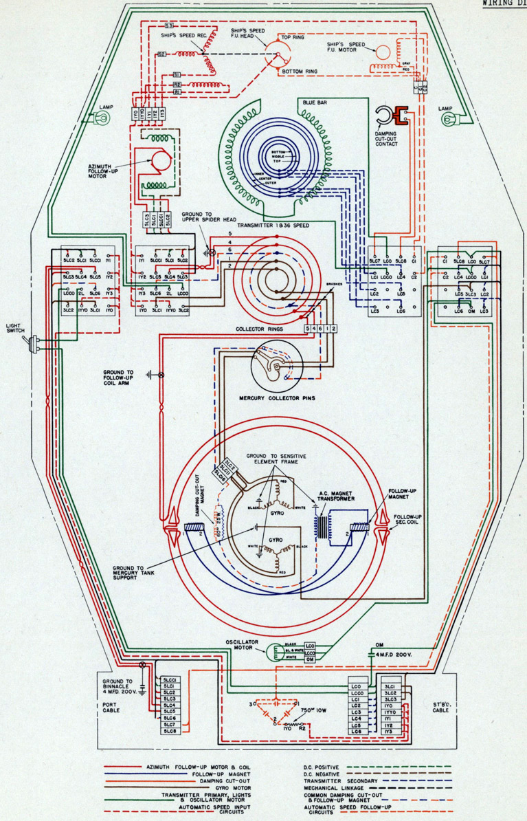
• Gyro Drive
The gyro wheels are driven by two-pole, three-phase, squirrel cage, induction motors whose supply is furnished by a motor generator set. Figure 55 is a schematic diagram of the gyro drive and follow-up system circuits. At the upper right corner of the diagram, the ship's D.C. supply is shown connected to the motor generator switch. In its "On" position the motor generator switch connects the D.C. line and the speed control rheostat to the motor generator set. Full voltage is available for the motor armature and generator field. The motor field is connected to the supply through a rheostat and a fixed resistor in series. Cutting out resistance on the rheostat decreases the motor speed. The motor generator set is constructed so that it will start directly across the line, hence no starting position is required on the switch.
As explained on page 11, the gyro wheels operate at different speeds in different latitudes. Since the gyro wheel speed is proportional to the frequency, which in turn is proportional to the speed of the motor generator set, the wheel speed may be varied by changing the motor speed. The rheostat which controls the motor speed is fitted with a dial calibrated in degrees of latitude to give the correct wheel speed for each setting. The effect of supply voltage variations is minimized by the design of the motor generator set, since a 5% voltage variation results in a 2-1/2% frequency variation.
At the equator the generated frequency is a maximum of 300 cycles, corresponding to a gyro wheel speed of 18,000 R.P.M. At 70° latitude the generated frequency is reduced to 102.6 cycles which gives a gyro wheel speed of approximately 6,000 R.P.M. The reduced generator speed at high latitudes results in a lower gyro supply voltage indication on the control panel meter.
• Follow-up Magnets and Damping Cut-Out Valve
The follow-up magnets and damping cut-out valve on the sensitive element are operated through one pair of leads. This is practical because the magnets require alternating current while the valve magnet is operated by direct current. Power is supplied from two transformers on the rear of the control panel, Figure 44.
The damping cut-out transformer primary is connected directly across the line as shown in Figure 55. The secondary voltage is impressed across a full wave metallic oxide rectifier. In this secondary circuit is a damping cut-out relay which lights a lamp on the control panel when the damping is inoperative. This relay is similar in operation and constriction to the synchro overload relay shown in Figure 46 except that only one side of the. primary is connected in the circuit. Direct current is carried to the damping cut-out magnet through two transformer windings and the sensitive element ground.
Alternating current for the follow-up magnets passes from the secondary of the follow-up magnet transformer, the primary of which is connected to the line in parallel with the damping cut-out transformer, to a transformer on the sensitive element through two resistors which shunt the rectifier and the damping cut-out magnets. The transformer on the element serves to keep direct current out of the follow-up magnets and to supply the magnets with 60-cycle current.
• Follow-up Coil
A small 60-cycle voltage is induced in the follow-up coil by the magnets on the sensitive element. The coil is wound so that the voltage induced in it when the coil is displaced in a clockwise direction from its normal position is opposite in phase from that induced when the displacement is in the other direction. Normally the voltages induced in the two halves are equal and opposite so that the net voltage is zero.
57
GYRO DRIVE & FOLLOW-UP CIRCUITS
FIGURE 55
MADE FROM
ARMA DWG. NO. 52456
58
• Amplifier
A two-stage amplifier steps up the follow-up coil voltage for control of the two grid-controlled rectifier tubes which actuate the follow-up motor. The amplifier, which is shown in Figure 56, is made up of several cased units. These units, containing transformers, chokes, condensers, rectifiers, etc., sectionalize the circuit according to function, and thereby greatly aid in testing, locating casualty, and replacing faulty units. Miscellaneous resistors and condensers are attached to a small bakelite panel which is mounted above the input transformer. The socket for the 6A6 amplifier tube is an integral part of the amplifier, and projects thru a hole in the follow-up panel. D.C. for the supply of the amplifier tube is produced in the amplifier unit by a full-wave, copper oxide rectifier, so that only a 115 volt, 60-cycle supply is necessary for, the operation of the unit.
The follow-up winding is connected to an input transformer in the amplifier thru a, cable which is shielded to keep out inductive and electrostatic pick-up. See schematic diagram, Figure 51.
The input transformer (T1) is shielded magnetically and electrostatically by alternate shields of copper and iron. In the secondary circuit of the input transformer (T1) are a resistor (R26) and small condenser (C10) which shift the phase of the signal voltage applied between one grid and cathode of a twin-triode type 6A6 amplifier tube (V1). The A.C. path from (T1) to cathode of (V1) is thru condenser (C15). The D.C. grid connection to the negative side of the D.C. supply is made thru filtering resistor (R27). These input circuits are shown as solid red lines, Figure 61. The second amplifier stage signal circuits, together with the first stage output circuit, are shown by solid blue lines in Figure 61.
The output voltage of the first stage triode (left half of V1) is developed across plate resistor (R25) and is coupled to the second stage triode (right half of V1) via condenser (C11) and gain control potentiometer (P1). This potentiometer is the sensitivity control, the dial of which may be seen directly above the amplifier tube in Figure 47. A fixed sensitivity is not used because of tube aging or replacement, and different operating conditions may require different adjustments for optimum operation.
The second stage of the 6A6 tube is transformer (T2) coupled to the C6A rectifier tubes (V2 and V3). A milliammeter (M3) in the interstage transformer (T2) primary circuit indicates the plate current. There is also a relay in this circuit to operate a flasher when the plate current falls approximately 0.7 milliampere below its normal value. When the follow-up coil is displaced more than about 1 degree, the plate current drops sufficiently from overloading of the tube to operate this relay. The alarm serves, therefore, to indicate failure of the follow-up coil in following the sensitive element.
The direct current plate supply for the first amplifier stage is filtered by choke (L3) and condenser (C13). Grid biasing voltage for both stages is developed across resistor (R24). The second stage A.C. grid return is thru condenser (C12), while the D.C. connection is made thru filtering resistor (R23). The direct current power input of the copper oxide rectifier is filtered by chokes (L1, L2) and condensers (C17, C18).
The 6.3 volt filament is heated by a small transformer (T3) connected to the 60-cycle A.C. supply. The function of the A.C. and D.C. bias transformers will be explained in the next section.
• Grid Control Rectifier Tubes
The C6A tubes are xenon gas-filled rectifier tubes having a plate, filament, and grid. One of the characteristics of these tubes is that no plate current flows until the grid becomes more positive than a certain critical value. When this voltage is reached, and there is a positive potential on the plate, the gas is ionized, and the tube shows a purple glow. Plate current then flows thru the tube, and will continue to flow until the plate voltage drops below the arcing potential. Reducing the grid potential after the tube becomes conducting will not interrupt the plate current flow.
The critical grid voltage at which the tube becomes conducting is dependent upon the plate potential. It may also change slightly during the life of the tube, going either up or down. Because this change is slight, and may be in either direction, it is impracticable to judge the life of the tube by it.
60
AMPLIFIER UNIT
FIGURE 56
61
Figure 57 represents the condition which arises when an alternating potential is connected between plate and filament, and when the grid potential varies as shown by the curve marked "A.C. Bias Voltage". As long as the grid is more negative than its critical value, no plate current flows, even though the plate voltage rises to a high positive value. When the grid reaches a certain potential, the tube becomes conducting. A heavy plate current flows with a small voltage drop in the tube. When the plate potential falls to a value insufficient to keep the gas ionized, the tube once more becomes non-conducting.
Xenon gas is used in the tube in preference to other gases, because it prevents changes in temperature from adversely affecting the tube operation.
• Grid Control Rectifier Tube Circuit
The amplified follow-up coil voltage is applied to the grids of two C6A grid control rectifier tubes whose plate currents operate the follow-up motor.
In Figure 61 the upper secondary winding, of the interstage transformer, (T2) is connected to #1 rectifier tube grid through a resistor (R12).
In series with the upper secondary winding of the interstage transformer (T2) is one winding of a grid bias transformer (T4), part of the anti-hunt unit circuit explained in the next section, and a small copper oxide rectifier (E2). The grid return goes to a center tap of the 2.5-volt filament transformer winding (T5). The small rectifier is supplied with A.C. from a rectifier bias transformer (T6), and furnishes a direct current potential of approximately 4 volts to bias the rectifier tubes. Ripples in the rectifier voltage are smoothed out by a resistance-condenser combination. When there is no voltage at the amplifier output, the rectifier tube bias is an alternating voltage superimposed on a steady voltage as illustrated in Figure 57 .
The two rectifier grid and plate circuits are alike, but the phases of grid and plate potentials are 180° apart.
An electrodynamometer type galvanometer, having one winding connected to the 60-cycle supply, and the other to the lower winding of the interstage transformer, indicates the proper operation of the rectifier tubes. If the azimuth follow-up coil is displaced to a lower card reading than is correct, a signal voltage is set up by the follow-up coil and amplified by the 6A6 tube. The rectifier circuit wiring is such that tube #1 operates to increase card readings and tube #2 operates to decrease card readings. In this case, the phase of the amplified voltage would be such that tube #1 would operate to bring the card to its proper position, and tube #2 would not function. The meter would then read "Tube #1 On - Tube #2 Off". Displacement of the coil to a higher card reading causes tube #2 to operate and the meter to read "Tube #2 On - Tube #1 Off". Thus, by indicating which tube should be "On" and which should be "Off", the meter serves to point out broken or defective tubes.
62
FOLLOW-UP SYSTEM
Referring to Figure 57, it is seen that when the follow-up coil is in its neutral position and no voltage is coming from the amplifier, the phase relation between grid potential and plate potential is such that plate current flows during a small part of the cycle which is marked by the shaded area. In order to obtain this relation, a phase shifter consisting of a series condenser (C14) and a shunt resistor (R22), is placed in the primary circuit of the grid bias transformer (T4), Figure 61. The plate current which flows does not turn the follow-up motor, because an equal current in the opposite direction flows through the other rectifier tube.
When toe follow-up coil is displaced from its neutral position, a voltage is induced in the interstage transformer secondary winding. This voltage added to the alternating bias potential has the effect of shifting the phase and changing the magnitude of the latter as illustrated in Figure 58. When the phase shift is in the direction shown, plate current flows through a larger than normal position of the cycle, causing the follow-up motor to run. When the follow-up coil is displaced in the other direction, the signal voltage from the amplifier reduces the grid potential during the half cycle in which the plate voltage is positive and no current flows through this tube.
A resistor is placed in the grid lead of each rectifier tube to limit the grid current when the tube is operating. A small mica condenser (C4) and (C5) connected from tube grid to the midpoint on the rectifier
filament transformer (T5) prevents transient voltages at the grid of one tube from affecting the other. To illustrate, if the condensers were omitted, operation of tube #1 would cause a sudden rise of grid potential which might feed back through the upper secondary winding inducing a voltage in the lower winding sufficient to cause plate current to flow in tube #2. Once started this current would continue to flow through the remainder of the half cycle.
• Sustained Oscillations or Hunting
The sensitivity of the circuit described above is adjusted by changing the amplification ratio of the amplifier. If the sensitivity is low, the follow-up coil must be displaced from its neutral position by an appreciable angle before the signal voltage, Figure 58, is sufficient to cause the tubes to run the follow-up motor. Increasing the amplification reduces this angle of "dead space", but if it is reduced too mach, continued oscillation, or hunting, of the follow-up mechanism results. It is assumed for the moment that the anti-hunt unit is inoperative.
The reason for hunting is illustrated in Figure 59 which shows a curve representing oscillation of the follow-up coil back and forth across its neutral position when the dead space has been reduced to a very small value by increasing the sensitivity of the amplifier. At position A the coil is displaced from its neutral position. Plate current flows through tube #1 turning the follow-up motor which drives the coil back along curve AB toward its neutral position. when the coil reaches B it is at the end of the very narrow dead space and the voltage induced in the follow-up coil is insufficient to operate the follow-up motor. However, there is a time lag in the amplifier and in the rectifier circuits so that the driving force continues for a fraction of a second until the coil reaches C. Just as there is a lag in the cut-off point of tube #1 there is also a lag in the starting of tube #2 which, when it starts to operate at D, opposes the inertia force of the follow-up mechanism until point E is reached and the coil has stopped.
In comparing curves ABC and DE it is apparent that more energy was added to the follow-up mechanism when it moved from A to C than was subtracted when it slowed down through the shorter distance DE. The difference in these two energies is what maintains the oscillation against the friction loss of the system.
The oscillation can be stopped by reducing the sensitivity to widen the dead space to a value such that the energy absorbed by friction is greater than the net supplied energy.
63
• Anti-Hunt Unit
In the Arma Compass an anti-hunt unit prevents oscillation of the follow-up system, even when the dead space is reduced to an extremely small value. The effect of the unit in operation is to shift the "cut-off" and "cut-on" points C and D as shown in Figure 60, so that at each swing of the follow-up coil past the neutral position the amplitude is reduced. This is accomplished by making the driving tube grid more negative as the coil approaches the neutral position, and making the grid of the other more positive.
As shown in the schematic diagram, Figure 61, the follow-up motor armature current passes through a resistance shunted by the primary of a transformer. When a tube is operating, a pulsating direct current flows through this resistor. Since these current pulsations are rapid in comparison with the frequency of hunting, only their mean value need be considered here. This current varies in magnitude with the displacement of the follow-up coil, being a maximum when the coil is farthest from its mean position. For this reason an alternating voltage of the mechanical oscillation frequency, in phase with that oscillation, is applied to the anti-hunt transformer. A phase shifter consisting of a condenser and resistance places a phase change of nearly 90° in the voltage before it is induced in the grid circuits by a second transformer.
Since the variation in grid bias produced by the anti-hunt unit is nearly 90° out of phase with follow-up coil displacement, the effect as the coil nears the neutral position is to increase the negative bias on the operating tube causing it to become inoperative sooner than it would without the anti-hunt unit. Thus the point C, Figure 59, is shifted to the position shown in Figure 60. The "cut-in" point D is shifted in the same direction because the grid bias of the tube which is about to operate is made more positive.
In Figure 60, it is apparent that the energy added to the follow-up mechanism from A to C is less than that subtracted from D to E. This condition results in damping, and permits the dead space to be reduced practically to zero, without resultant oscillation.
If the amplifier sensitivity is increased far beyond the value which effectively eliminates the dead space, the damping system will no longer be sufficient. Moreover, a large current will flow continuously through both the tubes and the follow-up motor, placing an unnecessary strain on the system. In addition, interference picked up by the coil is amplified to such an extent that it may become troublesome. For these reasons there is a practical limit to the sensitivity which may be used to advantage.
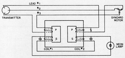
It is the function of the commutator transmitter and synchro motors to keep the repeater dials turning in synchronism with the compass card. This is accomplished by means of a transmitter on the master compass which energizes the armatures of synchro motors in the repeaters. All the motor fields and the transmitter are energized from a single-phase, 60-cycle supply.
• Synchro Motor
The synchro motor field is a laminated rotor having two poles. The stator is wound like a three-phase motor armature, but is a three-phase winding in structure only, since in operation it carries only single-phase current.
Figure 62 represents the synchro windings. The rotor field structure is energized with single-phase, 60-cycle A.C. The commutator transmitter introduces single-phase voltages in the three-phase windings of the stator. These voltages vary in amplitude and direction with respect to each other, but do not vary in phase. Consider the stator voltages as shown in the diagram. During one half-cycle the top and bottom field poles are North and South, respectively. The stator voltages are such as to make coil S2 a South pole, which attracts the North end of the rotor. The voltages acting on coils S1 and S3 cause these two poles to act as a single North pole which attracts the South end of rotor, causing it to assume the position shown. During the next half-cycle, all polarities are reversed. Therefore, the equilibrium position is not changed. Actually, in the synchronized position there is no current flowing in the stator coils, since the rotor induces currents equal and opposite to the transmitter currents. However, if the rotor is forcibly displaced, unbalanced voltages instantly develop a torque tending to restore it to the neutral, or synchronized, position.
When it is desired to change the position of the rotor, to which the repeater card is attached, it is only necessary to change the voltages between the stator leads, so that the resultant magnetic effect of the three coils is along the new desired axis. The rotor will then align itself with its poles on this new axis.
• Commutator Transmitter
The transmitter furnishes the synchro motors with voltages which keep the repeater dials turned in synchronism with the compass card.
The principal electrical elements of the transmitter are an auto transformer, a commutator, and a set of three brushes. Actually there are two sets of brushes, but since they work on the same principal only one set is considered here.
The auto transformer winding, Figure 63, is wound on a circular core. A short distance above the transformer is a commutator having 360 radial segments. These segments are connected to taps on the transformer winding. Three brushes, spaced about 120 degrees apart, rest on the commutator segments and turn with the compass card.
The extremities of the transformer winding are connected to the segments as shown, 104 volts of the line voltage being between the segment at 0° and the one at 180°. This value of 104 volts is chosen in order to have the maximum potential between brushes equal to 90 volts. Segments in corresponding positions on opposite sides of the commutator are connected together as shown by the dotted lines. Taps on the windings are so spaced that the voltage distribution around the commutator is
68
TRANSMITTER AND REPEATER
sinusoidal, as shown in Figure 64. The voltage between the 0° segment, which is painted blue, and any other bar α ° away is:
Line Voltage = (1 - Cos α) x (Line Voltage 104/115) / 2
One of the brushes is painted blue. When this brush is on the blue segment the other brushes, which are painted red and green, will rest on segments of corresponding color. The brushes are then on "electrical zero". The voltage between the blue and red or blue and green brushes is:
[1 - (-1/2)] 104/2 = 78 volts
The voltage between red and green brushes is zero because they rest on segments which are connected together. If the brushes are connected to a synchro motor, the motor will take up the position shown in Figure 62, and the dial reading will be zero.
When the brushes are turned on the commutator, the voltages between them change. The voltage between any two brushes varies as a sine curve as they are turned on the commutator. This is the condition necessary to keep the synchro motor armature turning in synchronism with the commutator brushes.
In order to give a smooth change of voltage as the brushes rotate, the brushes are offset 1/3 of a commutator segment from a true 120° spacing.
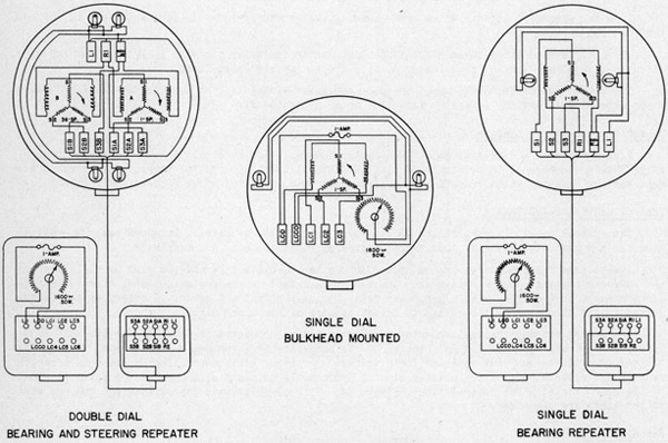
• Repeater Wiring
There are five leads to each synchro motor. Two are for the field and three for the armature. Where two synchro motors are used in one repeater, the fields are connected in parallel and there are eight active leads. The 130-volt lamps are connected to the field circuit. A rheostat in the connection box is in series with the lamps to permit dimming. This necessitates an extra lead between the connection box and repeater. Repeater wiring is illustrated in Figure 67.
Each repeater cable terminates at a switch on the repeater panel. This switch connects the armature leads to the transmitter brushes, and the field to the single-phase supply on the control panel. Leads are fused as described on page 46. Only five switch poles are required by the single dial repeaters, but all repeater switches are made to control at least two synchro motors.
• Synchro Motor Overload Relay
On the repeater panel there is a trouble indicator
lamp for each repeater. The lamp is operated by a synchro
motor overload relay connected in the motor stator leads.
The overload relay seen on the back of the repeater panel,
Figure 44, is a universal type which may be used with
several types of transmitters. For this reason there are
more terminals on the relay than are used in the compass
equipment. Figure 65 is a schematic diagram of the relay as used in the compass equipment. Two pairs
of windings are wound on one core. Each primary winding consists of comparatively few turns connected
in a stator lead. The secondary windings are made up of many turns, and are connected in series with
each other and with a neon lamp. When the synchro motor follows the transmitter properly, only a small
current flows in the stator leads, and the voltage induced in the secondary windings is insufficient
to light the lamp. If the repeater fails to follow the transmitted heading within from 15 to 20
69
degrees, the stator current rises sufficiently to light the lamp. The reason for having two pairs of windings is that there can arise a condition in which the repeater does not follow, and still the armature current in one line is zero. It is also possible to find a condition in which the currents in two leads are of equal magnitude and opposite phase, so that the voltage at the lamp would be zero if it were not for the condensers and resistors which shift the phases so that this cannot happen.
There are two overload relays on the panel for repeaters having two synchro motors. They have separate neon indicating lamps, so that the motor in trouble can be readily identified. Spare switches are also supplied with two sets of relays and lamps, thereby permitting the connection of any type of repeater.
OVERLOAD RELAY
FIGURE 65
70
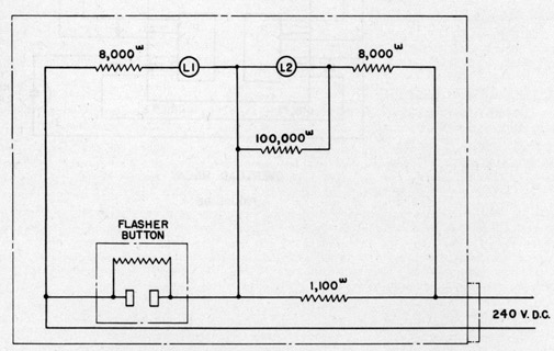
ALARM FLASHER
The alarm flasher, by means of two alternately flashing neon lamps, indicates trouble in the compass power supply or follow-up system. The alarm flasher circuit, operating on a 240 volt D.C. supply, is arranged as shown in Figure 66.
A flasher button is used to control the circuit. When this device is energized, it alternately changes its resistance from approximately 5000 ohms to a short circuit. Disregarding the 8000 and 100,000 ohm resistors for the moment, when the flasher box is energized, the 240 volts is applied to the flasher button in series with the 1100 ohm resistor. Thus, when the flasher button presents a resistance of 5000 ohms, about 5/6 of the line voltage will be across the flasher, and about 1/6 across the 1100 ohm resistor. The latter voltage is insufficient to light lamp L2, but the larger voltage across the flasher causes L1 to ignite. Now, when the flasher button shorts itself, lamp L1 will be shunted out, and lamp L2 will then have the full line voltage applied across it, causing it to light in turn. This alternate flashing continues until the supply is turned off.
Since the neon lamps are designed to operate from 115 volts D.C., an 8000 ohm resistor is placed in series with each, to prevent damage from the 240 volt alarm supply. The 100,000 ohm resistor shunted across L2 prevents this lamp from glowing due to the low voltage (about 40 volts) remaining across it when L1 is operating.
ALARM FLASHER
MARK 1 M00. 0
FIGURE 66
71
WIRING DIAGRAMS
• General
The principal electrical circuits are illustrated and explained in the schematic diagrams in the preceding section. These circuits include electrically related equipment even though the circuit elements may be far apart. This section on wiring diagrams shows the connection between parts which are all in one mechanical unit such as the master compass or control panel. Connection between units is made through cables connected to terminal blocks marked to indicate the nature of the circuit with which each terminal is associated.
• Circuit Designation
All gyro compass circuits are marked LC. The circuits are further distinguished in accordance with naval specifications as follows:
LC - Single phase 60-cycle or repeater circuits
1LC - 115-volt D.C. circuit
3LC - A.C. gyro motor circuit
4LC - A.C. alarm circuit
5LC - Follow-up amplifier and follow-up motor
In a two wire circuit both wires are marked alike except for the letters which are LC for one lead and LCC for the other.
In a three-wire three-phase circuit the last number indicates the wire 1, 2 or 3. In repeater circuits 1, 2, 3 are single-speed leads; 4, 5, 6 are thirty-six speed leads.
The second number following the LC in motor generator wiring is 1 or 2. The numeral 1 indicates motor generator #1 and the numeral 2 indicates motor generator #2.
• Master Compass Wiring Diagram
Figure 68 is a wiring diagram of the master compass. The terminals on the blocks in the binnacle base are connected to terminals of similar designation on the control panel. All circuits except that of lights, which is self-explanatory, have been explained under "Schematics", page 56.
• Control and Follow-up Panels
The control panel diagram, Figure 69, includes the follow-up panel. It shows how the various circuits are connected together, and to the switches, fuses, meters, and terminals.
Low-voltage relay windings are connected across the 60-cycle line and the gyro supply. When in the released position these relays and the sensitive relay on the follow-up panel close a simple alarm circuit consisting of an alarm power relay, a switch, and a flasher. A rotary switch is inserted in the circuit with the relays to permit testing of the alarm circuit.
The master compass transmitter auto-transformer is not connected directly to the 115 volt A.C. lines, as are the repeater fields, because it is necessary to introduce a correction to keep the transmitter voltage and the repeater field voltage in phase. This correction is made by a series reactor and resistance. The transmitter winding is connected in shunt with the reactor which is shown on the door bracket of the control panel, Figure 44. This circuit draws approximately 6 amperes when no repeaters are connected.
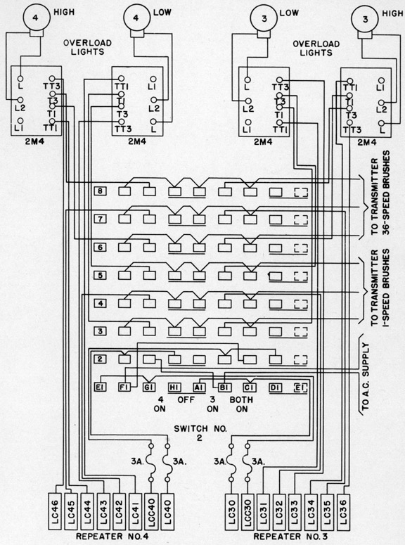
• Repeater Panel
The repeater panel wiring for Mods. 0 and 1 is shown in Figure 70. Eight leads connect the repeater panel to the control panel. Six of these leads are for the single and thirty-six speed transmitter connections. The other two carry 115 volt A.C. for the repeater fields and lights.
Each switch is wired to the eight transmitter and field leads, Figure 71. It is also wired through connection blocks to the repeater compasses. Each repeater switch controls two repeaters. The switches are wired so that the repeaters may be energized separately or together, with the exception of the Sound Stations #1 and #2, which are both on one throw of Switch No. 6. Should one of the two repeaters connected to a switch fail, the switch must be turned to the "On" position for the other repeater so that the disabled one will not affect the circuit.
Four of the connections between the switch and each repeater are made through windings of overload relays as explained on page 68.
72
• Repeaters
In Figure 67 are shown the wiring connections within the various types of repeaters and in the connection boxes. Field and armature connections are made through the connection box and ship's cable to the repeater panel. Terminal designations are as shown in the figure. Power for the lights is taken from the field supply, and a rheostat in series with the lights permits them to be dimmed or turned off. The light circuit is protected by a 1-ampere indicating fuse in the connection box.
REPEATER COMPASSES
WIRING DIAGRAMS
FIGURE '67
73
ARMA DWG. 56375
MASTER COMPASS
SCHEMATIC WIRING DIAGRAM
FIGURE 68
The accuracy of the compass is dependent upon the preservation of the balances and extreme freedom of its moving parts. Take every reasonable precaution to protect the compass and avoid rough handling as this is particularly injurious to the instrument.
When shipped from the factory, snipping clamps were fastened to the lower bowl to hold the unit in place during shipment. A shipping clamp was also attached to the gyro units on the sensitive element. The mercury was removed from the ball float tank and collector cups.
When unpacking the equipment, inspect each part for possible damage in shipment and wipe the dust and dirt from all parts before installation. Before taking the compass aboard ship, drain the oil from the oscillator mechanism to prevent the possibility of spilling oil.
• Installation of Binnacle, Gimbal Rings and Bowl
As the binnacle is too large to pass through small submarine hatchways, it will be necessary to remove the gimbal system and disassemble the binnacle as follows:
1. Remove the 16 felt-tipped spring damps from the inner gimbal ring. Suspend the gimbal rings and proceed to remove the bearing pivots. The gimbal rings and suspended parts may now be lifted slightly from the binnacle to allow removal of the cable clips which are fastened to the gimbal rings. Disconnect the electrical conductor of the oscillator motor at the gang plug assembly. Drain the oil from the oscillator mechanism by removing the drain plug at the bottom and tilting the lower bowl at a slight angle. The gimbal rings and suspended parts are now free to be removed from the binnacle as a unit. Allow the bowl to rest on a firm support.
2. Note the position of the lower bowl with relation to the gimbal rings and proceed to detach the bowl suspension springs from the inner gimbal rings. Lower the gimbal rings and place them on a firm support. Separate the cuter gimbal ring from the inner ring by removing the bearing pivots. The gimbal rings can now be separated into two halves by removing the screws and slip dowels at the junction points. Lower the gimbal rings through the hatchways.
3. Remove the bezel clamp ring in the binnacle cover to enable the binnacle window glass to be removed, and proceed to split the cover vertically into two parts.
4. Detach the terminal block supports from the lower binnacle and remove the binnacle base. The lower binnacle can now be vertically split into two parts, and the sections may be taken aboard ship through the hatchways.
5. Secure the binnacle base to the deck with the fore and aft lines on the base as nearly parallel to the ship's centerline as possible. Assemble the binnacle cover and the lower binnacle. Mount the lower binnacle on the base with the holding down bolts near the center of the slots in the flanged ring.
6. Assemble the gimbal rings, and attach the bowl suspension springs to the inner gimbal rings, making certain that the cowl is in correct position in relation to the gimbal rings. Carefully lower the suspended parts into the lower half of the binnacle with the lubber line forward. Insert the cuter gimbal ring pivot bearing and locknuts and attach the spring damps to the inner gimbal ring.
7. Connect the electrical conductor of the oscillator motor to the gang plug assembly. Attach gimbal ring cable clips and the terminal block supports. Connect the electrical conductors from the control panel to the terminal blocks at the binnacle base as indicated by the terminal markings which correspond with markings on the control panel terminal blocks. In connecting shielded cables be sure to carry the shielding right up to the terminal block.
8. Clean out the mercury tank thoroughly. Use a little cleaning fluid (alcohol, benzine, etc.) to remove all grease. Cover with clean paper (not cloth) to keep out dust and lint until the sensitive element is out into place. Fill the oscillator mechanism with oil supplied for this purpose. See rage 90 for detailed instructions.
9. When ready for installation of sensitive element, place mercury designated for the compass into the mercury tank. Be careful to keep it clean. Approximately 9 lbs. of mercury are required.
• Installation of Sensitive Element
1. Exceptional care must be used in handling the sensitive element. Have the element, in its crate, gently lifted on board. Unpack carefully, avoiding jars or blows. Suspend the element by means of the two eyebolts supplied for this purpose. If it is necessary to lift the element by hand
82
INSTALLATION
grasp it firmly under the frame, never by the gyro units. Do not let the hoist chain or other objects strike against the coupling linkage or levels. Leave the shipping clamp in place on the gyros.
2. Carefully lower the element down the hatchway to where the binnacle is set up, keeping in mind that a slight blow might render the element inoperative.
3. Unscrew the float ball, which is fastened by a right-hand thread. Clean the ball thoroughly to remove grease, using a little cleaning fluid. Now, place the Bakelite mercury pot collar on top of the ball, and screw the ball on again. When replacing the ball and collar, be sure the ball is all the way on, and is securely in place, by first backing the ball off about a quarter turn, then screwing it up with a quick twist of the hands.
4. Remove the gyro shipping clamp, and hook on the gyro centering springs, which are attached to the sensitive element frame with gummed paper tape. Be careful not to distort these delicate springs.
5. Do not change the position of any adjustable weights.
6. Inspect the gyro vacuum gauges. The gauges should read approximately 29 inches.
7. Inspect the gyros to see that they oscillate freely about the vertical, that the coupling links have not been bent, and that the centering springs have not been pulled out of shape.
8. Clean off the entire element making sure that no dirt, mercury, or other foreign material has lodged in any of the cavities. This is important, because even a small extra weight will disturb the balance and pendulous factor.
9. Clean out the mercury cups at the center of the element with a damp cloth, and allow the cups to dry. Fill the outer cup to a depth of 3/4 inch, the middle cup to a depth of 1/2 inch, and the center guide bearing half way to the top. The mercury surface level in the two outer cups will be at the same height. See Figure 31, page 24. As cleanliness is essential, the opening above the cups should be covered with clean paper until the spider assembly is put in place.
10. Slowly lower the element into the bowl, being careful not to strike the float ball against the mercury tank. When the element is lowered into place, the mercury collar will rest on the rim of the mercury tank supported by the spring clips. The collar must be seated slowly to prevent spillage of mercury.
• Installation of Spider Assembly
1. Have the spider assembly, crated, lifted on board and unpack it, being careful not to damage the follow-up coil located on the lower side.
2. Clean grease from contact pins with cleaning fluid, and examine them to make sure they have not been bent. See Figure 31 for correct shape.
3. The spider assembly is put in place with the lubber line forward. If no hoist is available, have two men grasp the spider, being careful not to lift or press against the follow-up arms. Lift high, so that follow-up coil and contact pins will clear binnacle. Place directly over bowl, and lower slowly keeping spider and bowl horizontal. Be careful not to bend the contact pins as they enter the mercury cups. The sensitive element should have perfect freedom for turning or tilting. If any resistance is observed, remove the spider, examine contact pins, bending them back into position if necessary, and replace spider as instructed above. Be sure to keep bowl and spider horizontal as otherwise the contact pins will not come down in proper place. When properly installed, secure the spider screws.
4. Lay a straight-edge across the topmost surface of sensitive element to see if this surface is level with the reference line on the contact pin support tube. Add or remove mercury until flotation is correct to within 1/32".
5. If it is desired to turn follow-up coil by hand, this can be done by turning the 36-speed compass dial. Do not force the follow-up arms, or the driving mechanism will be strained.
• Alignment of Compass
1. The base should be bolted to the deck with its fore and aft line approximately parallel to the ship's center line.
83
2. Loosen the bolts inside the binnacle which hold the binnacle to the base. Shift the binnacle until the fore and aft line of the compass is parallel to the ship's center line.
3. After the compass has been put in operation and the element has settled, compare compass reading with ship's heading. If the compass is functioning properly, but shows a constant error in the settling point, correct by shifting the follow-up arms. This may be done by loosening the three screws which clamp it to the stalk.
84
OPERATION
• General
The gyro compass is a sensitive instrument. The first essential in its operation is to see that no one but an authorized person has access to it. Never attempt to disassemble or adjust it before carefully reading the chapter on adjustments. No person other than qualified Gyro Compass repair personnel should ever attempt a major repair or adjustment.
• To Start the Master Compass
(1) The compass should be started about four hours before it is required for service.
(2) Check vacuum gauge reading of North and South gyro units. The vacuum should be approximately 29 inches. Any sudden change from a previous reading should be investigated.
(3) Check oil level in gyro case. Level should be approximately half way up on sight glass at bottom of case. This check maybe easily made by holding a mirror next to the sight glass and viewing the reflection of the oil level in the mirror.
(4) Make certain that there are no foreign objects lying anywhere on the sensitive element. Put the spider doors into place and close hinged door in binnacle cover. By means of the "Manual Input Speed" knob, set the "Corrector Setting Knots" counter at zero.
(5) See that all switches on the control and repeater panels are in the "Off" position. The damping cut-out switch is an exception to this rule and should be in the "On" position, when the ship is not making way. See Item 14, page 85.
(6) Have the power supplies to the control panel energized.
(7) Turn the A.C. and D.C. supply switch to the "Fil. Only" position. Let it remain here for five minutes to allow the rectifier tube filaments to become heated, then turn it to the "On" position. The amplifier tube plate milliammeter should read approximately 2.3 milliamperes at 115-volt, 1-phase supply. Any reading between 1.5 and 2.5 milliamperes is normal.
(8) After the A.C. and D.C. supply switch has been turned to "On", check operation of the azimuth follow-up system by turning the follow-up motor switch to "Azim. Only". If the follow-up system is operating properly the follow-up motor will immediately bring the follow-up coil into its correct alignment with the sensitive element. Compare the card reading with the emergency azimuth scale reading. After checking this reading turn the follow-up motor switch to "Off", until the gyros have been started and have come up to speed. NOTE: If the alarm switch is "Normal", the alarm will flash until the follow-up coil comes to within about 1 degree of its correct position. It will continue to flash if the gyros have not been started. For this reason, the alarm switch is left in the "Off" position until the compass is operating.
(9) Set the "Latitude" dial on the control panel and the "Latitude" correction knob on the master compass spider assembly to the correct latitude. On the sensitive element set the latitude leveling weight to the ship's latitude. For an extended voyage, the weight should be set at the middle latitude of the ship's intended traverse. Adjustment of the latitude leveling weight should be made only when the gyro wheels are not running, or when the compass is not needed for several hours, as the shift in weight on the element will disturb its equilibrium, and several hours will be required until the element settles again.
Turn the sensitive element by hand to a position within about 15 degrees of the meridian. Turn the motor generator switch to one of the "On" positions and observe the sensitive element. If the wheels are turning in the correct direction, the element will tilt up on the East side as shown by the East-West level. The spiral lines on the gyro wheels as seen through the sight glasses will appear to move from the North toward the South. Turn the gyro drive ammeter switch through all three positions to make sure current is flowing in each phase. Due to the heavy starting current, the meter will read off scale until the wheels have been running several minutes, hence the switch should be left in a neutral position until the wheels have come up to speed, as indicated by the A.C. voltmeter.
(10) If the compass is being started for the first time after being installed or having a gyro unit changed, stand by the compass wheels until they are up to speed, which takes about 10 minutes. During this time feel both gyro units to detect excessive vibration due to damage which might have occurred in shipment.
(11) The gyro wheels come up to speed in about 8 or 10 minutes. After this length of time check the current in each phase of the gyro supply. The normal running current is about 1.7 to 2.6 amperes. If the wheels have not come up to full speed the current will be higher. The current drawn by the three phases should be the same within about 0.2 ampere. If the current is excessive after the wheels have had plenty of time to come up to speed, investigate the source of trouble before the gyros are damaged from overheating. Low vacuum is the first thing to look for. See "Troubles and Remedies", page 95.
85
(12) When the wheels are up to speed, turn the follow-up motor switch to "Azim. Only" position. Turn the alarm selector switch to "Normal" position.
(13) Check the A.C. and D.C. voltages. See Item 18 for normal values.
(14) Check the damping cut-out system by turning the "Damping" switch to "Off". The lamp on the control panel should light indicating cut-out of damping.
As soon as the ship begins making way, turn the damping cut-out switch to "Automatic". This switch should always be in the automatic position when the ship is making way unless the navigator directs that it should be turned to another position. The navigator may direct that the switch be turned to "Off" during rapid speed changes to eliminate the damping error, but if left in the "Off" position more than five minutes, the compass may start to oscillate across the meridian. The navigator may also direct that the switch be turned to "On" when making wide turns lasting more than five minutes, such as for calibration of the magnetic compass. The switch must always be in the "On" position when not making way.
(15) By means of the "Manual Input Speed" knob, introduce the value of ship's speed into the correction mechanism. If the underwater log input is available proceed as follows:
To start the automatic speed corrector, turn the follow-up motor switch to the "Sp. Corr. & Azim." position. Observe the reading of the pointer on the synchro shaft, and by means of the "Manual Input Speed" handle, set the counter to match this reading, approximately. This insures that the follow-up head will synchronize itself in the correct direction. Incorrect synchronism would result, if, at the time the speed input is turned on, the synchro motor is over one-half turn (about 12 knots on the scale) away from the position of the follow-up head. The speed corrector follow-up mechanism operates at a maximum rate of 10 knots per minute. Set the latitude knob to agree with the ship's position. For accurate results, this knob must be reset as the latitude changes. This is particularly important at high latitudes. If it is desired to operate the speed corrector manually, the correct switch should be turned to "Azim. Only" position.
The following table extends the range of the speed corrector from 70 degrees latitude to 80 degrees. When sailing at latitude of over 70 degrees, the "Latitude" knob on the corrector is set at 70 degrees, and the speed value from the table below set into the corrector manually. The detailed steps are as follows:
1. Set motor generator speed control on panel at 70 degrees.
2. Turn follow-up motor switch to "Azim. Only" position.
3. Set "Latitude" knob on master compass at 70.
4. By means of "Manual Input Speed" knob, set "Corrector Setting, Knots" counter on speed corrector to figure given in table below. For example, if the latitude is 74 degrees, and the ship's speed is 15 knots, set counter to 18.6 knots.
SPEED - KNOTS
Latitude Degrees
5
10
15
20
25
30
35
40
70
5.0
10.0
15.0
20.0
25.0
30.0
35.0
40.0
71
5.3
10.5
15.8
21.0
26.3
31.5
36.8
42.0
72
5.5
11.1
16.6
22.1
27.7
33.2
38.7
44.3
73
5.8
11.7
17.5
23.4
29.2
35.1
40.9
74
6.2
12.4
18.6
24.8
31.0
37.2
43.4
75
6.6
13.2
19.8
26.4
33.0
39.6
46.3
76
7.1
14.1
21.2
28.3
35.3
42.4
77
7.6
15.2
22.8
30.4
38.0
45.6
78
8.2
16.5
24.7
32.9
41.1
79
9.0
17.9
26.9
35.9
44.8
80
9.8
19.7
29.5
39.4
49.2
Note: Since the maximum setting of the motor generator speed control is 70 degrees, the ballistic deflection will not be correct at latitudes above 70. A temporary error will occur following a large change in course, or after a rapid change in ship's speed, when the speed change has a North or South component. In the above table, values above the maximum setting of the counter are for interpolation purposes. For example, when the speed is 28 knots at 76 degrees latitude, the value lies 3/5 of the way between 35.3 and 42.4:
On a compass with the counter stop set at 40.0, this value is within the range of the mechanism. Interpolations for latitude can be made in a similar manner.
(16) Keep the spider covers and binnacle cover door closed except when making an observation or adjustment. These covers keep out dust and reduce temperature fluctuation.
(17) Read gyro current in each phase every hour. The current should be about 1.7 to 2.6 amperes. An abnormally high current indicates trouble. Investigate immediately. See page 95.
(18) Read all voltages and currents every hour. Normal values are as follows:
Gyro current
1.7 to 2.6 amperes
Repeater system current
See below
D.C. voltage
115 volts
A. G. single phase
115 volts
A.C. gyro drive voltage
See below
Amplifier tube plate current
1.5 to 2.5 milliamperes
The instrument marked "Repeater System Current" indicates the current drawn by the transmitter circuit and repeaters. It will read about 5 to 6 amperes when no repeaters are connected. The reading should increase about 0.6 ampere for each additional synchro motor added to the load.
The gyro supply voltage is dependent on the motor generator speed which varies with the latitude and the D.C. supply voltage. When the D.C. voltage is normal (115 volts) the gyro supply voltage should have approximately the following values.
Lat.
Gyro Voltage
M.G. Speed
Lat.
Gyro Voltage
M.G. Speed
0°
68 ± 5 volts
3000 R.P.M.
47.5°
46 ± 5 volts
2025 R.P.M.
10°
67 ± 5 volts
2955 R.P.M.
50°
44 ± 5 volts
1930 R.P.M.
20°
64 ± 5 volts
2820 R.P.M.
52.5°
41 ± 5 volts
1830 R.P.M.
25°
62 ± 5 volts
2720 R.P.M.
55°
39 ± 5 volts
1720 R.P.M.
30°
59 ± 5 volts
2600 R.P.M.
57.5°
37 ± 5 volts
1610 R.P.M.
35°
56 ± 5 volts
2460 R.P.M.
60°
34 ± 5 volts
1500 R.P.M.
40°
52 ± 5 volts
2300 R.P.M.
62.5°
31 ± 5 volts
1385 R.P.M.
40.7°
51 ± 5 volts
2275 R.P.M.
65°
29 ± 5 volts
1270 R.P.M.
42.5°
50 ± 5 volts
2210 R.P.M.
67.5°
26 ± 5 volts
1150 R.P.M.
45°
48 ± 5 volts
2120 R.P.M.
70°
23 ± 5 volts
1025 R.P.M.
• Power Requirements of Compass Equipment
These values are approximate.
(1) Total D.C. consumption (maximum)
115 volts
8 amps.
920 watts
(2) Total A.C. consumption (30% power factor)
115 volts
25 amps.
2.9 kva.
(3) Gyro 3-phase consumption This power is furnished by the compass motor generator and varies with the latitude at which the compass is operating.
0° Lat.
67.5 volts
2.3 amps.
0.27 kva.
70° Lat.
23 volts
2.3 amps.
0.09 kva.
(4) Each single dial repeater draws from the control panel:
115 volts
0.6 amps.
0.07 kva.
(5) Each double dial repeater draws from the control panel:
115 volts
1.2 amps.
0.14 kva.
• Use of Level in Settling Element on Meridian
Ordinarily the master compass is started several hours before it is needed for service. If it is necessary to put the compass in operation on short notice, considerable time may be saved by precessing the element onto the meridian by hand. Precess as follows:
(1) Start the compass in the manner described above.
(2) Determine the approximate ship's heading.
(3) Precess the element until the card indicates the ship's heading. This is done by pressing down lightly on the North or South side of the element. To obtain higher card readings, press down on the North side. To obtain lower readings press down on the South side.
87
(4) Bring bubble in North-South level to center of scale. To do this press against the end of the bubble tube in the direction the bubble must go.
(5) Observe the North-South level for a five minute period. If the bubble moves toward the North, that is to higher readings, it indicates that the element is off the meridian and should be precessed to a higher card reading. The number of divisions the bubble moves in a five minute period is the approximate number of degrees the element if off the meridian.
(6) The bubble maybe observed for another five minute period and a second azimuth setting made.
(7) If the bubble stays nearly centered but the card reading changes during the five minute observation period, the bearing is nearly correct but the element is not leveled in its final settling position, or, what is much more likely, the damping oil has not reached its equilibrium distribution. Time must be allowed for the oil to come to rest.
(8) It is impractical to set the compass and have it remain exactly in its settled position because the damping oil must seek its final level and because temperature changes as the instrument warms up cause slight disturbances. The spider covers and binnacle cover door should be closed while the compass is settling.
• Position of Bubble when Element has Settled
When the element has settled on the meridian, it is desirable that the bubble in the North-South level be on the scale. If the bubble is off scale, the settling point will not be affected, but changes of motor generator supply voltage or frequency will produce an acceleration or deceleration of the gyro wheels and the reaction upon the sensitive element will turn it off the meridian.
If the North-South bubble is consistently off scale after the compass has settled, the bubble should be brought back on the scale by shifting the weight a quarter turn the next time the compass is shut down. See page 102.
The East-West level adjustment is not critical and need not be changed unless replacements are made on the element.
• To Shut Down the Compass
To stop the compass turn all switches on the control and repeater panels to the "Off" position. The damping cut-out switch may be left in the "On" position. No further attention is required. The gyro wheels will continue to rotate for two or three hours. Do not attempt any work on the element until the wheels have stopped.
88
CARE AND MAINTENANCE
• When to Make Inspections and Checks
The gyro compass requires little attention if operating instructions are carefully followed. Inspection, cleaning, and oiling should be done regularly in accordance with the schedule below. Visual inspection may, of course, be made at any time, but as long as the compass is operating satisfactorily it is best not to perform the other checks more often than indicated by the schedule.
Never shift a weight or make any other adjustment until it is definitely known that trouble exists, and until that trouble has been analyzed in accordance with the table, Page 95. Read section on adjustment, page 101.
LUBRICATION CHART
Read specific instructions in Maintenance Schedule.
PARTS TO BE CHECKED OR LUBRICATED
EVERY MONTH
EVERY 12 MONTHS
EVERY 24 MONTHS
Motor Generator Bearings
Starfak "M" or any medium grade grease Spec. #14G1
Commutator Transmitter Collector Rings & Bars
Gulf Precision Grease No. 1
Spider Collector Rings
Gulf Precision Grease No. 1
Oscillator
Nujol or Fractol "A"
Gyro Wheels
Gyro Oil #7380
Gyro Linkage
Gulf Precision Grease No. 1
Gyro Stem Bearings
Gulf Precision Grease No. 1
Gimbal Ring Bearings
Gulf Precision Grease No. 1
Follow-up Motor Bearings
Gulf Precision Grease No. 1
Upper Spider Bearings & Gears
Gulf Precision Grease No. 1
Multiplier Lead Screws
Gulf Precision Grease No. 1
Synchro Bearings
Shell Hydraulic Gear Oil V994
MAINTENANCE SCHEDULE
• Every Hour
Check gyro current and voltages. See page 86 for proper values.
• Every Watch
Inspect for burned out vacuum tubes. Make immediate replacement of defective tubes.
89
• Every Week
Check vacuum gauge readings. A reading of about 29 or 30 inches is normal. Small changes from previous readings maybe due to variations in barometric pressure. A large change indicates trouble.
Clean control and repeater panels. Inspect for loose connections and blown fuses.
• Every Month
Clean motor generator set. Turn down each grease cup 1/2 turn. When cup is empty, refill with a good grade of grease suitable for ball bearings, such as Starfak "M" or any medium grade grease as specified in Navy Spec. 14G1.
Caution: Before performing the following inspections, turn off the compass power supply.
Clean binnacle inside and out, making certain that no foreign objects have fallen across terminal blocks in base.
Clean bowl and spider.
Remove the spun aluminum cover from the transmitter head and examine the commutator transmitter collector rings and bars. Clean with a cloth dampened with alcohol, and apply the thinnest possible layer of Gulf Precision Grease No. 1. Keep the commutator bars and slip rings clean and smooth. If it is necessary to smooth the bars and slip rings, use a clean #6 file, never emery cloth. Clean parts thoroughly, being careful not to spill cleaning fluid on bearings or painted surfaces. Examine the damping cut-out contacts, and, if necessary, wipe off with a cloth dampened with alcohol. Do not lubricate.
Remove the spider covers and examine the collector rings. Clean the rings and apply a thin layer of Gulf Precision Grease No. 1.
Remove and inspect the follow-up motor brushes. The square portion of a new commutator brush is 17/32" long. When worn to 3/8", brush should be replaced.
When gyro wheels are not rotating, clean entire sensitive element. Check all adjustable weights to make sure none has worked loose, but do not move any of the weights. Check to see that the gyro units oscillate freely about the vertical. If excessive friction is noted, proceed as directed under "Once a Year".
Check flotation of element by placing a straight edge across the top of the sensitive element to see if line on contact support tube is level with this surface. Add or remove mercury to obtain this condition. When adding mercury do not let it spill on element. If mercury should be spilled on element be sure it is all brushed off and cleaned out of pockets around damping tanks and other places.
Check level of oil in gyro wheels. The oil should be at least 1/8 of the way up the oil sight glass. If the oil is over 3/4 of the way up the glass the reservoir has been overfilled.
To drain or refill the gyro, first open the exhausting valve thereby letting air into the case. To drain, tilt the gyro slightly and remove the drain plug at the bottom of the unit. To refill, tilt the gyro up and add oil through the same opening. When adding oil, rock the gyro slightly to dislodge any air bubbles which may have formed at the oil sight glass or in the oil reservoir. If the wheel has been in service for more than a year, it may be advisable to drain all the old oil. To do this, it will be found much Tore practical to remove the sensitive element, and, when it is on the bench, to remove the gyros. Use Gyro Oil #7380, manufactured by the Standard Oil Company of New Jersey. A supply of this oil is furnished in the spare parts box. If none is available, use an oil having approximately the following characteristics:
Gravity
33.6 A.P.I.
Flash Point
325° F.
Fire Point
365° F.
Pour Point
30° F.
Saybolt Universal Viscosity
60 seconds at 100° F.
Saybolt Universal Viscosity.
35 seconds at 210° F.
Carbon Content
0.01%
A slight difference in oil level maybe observed when the wheel is running, but the correct level will return when the wheel has stopped.
Before checking the oil in the oscillator mechanism, it is advisable to cover the terminal blocks
90
and other apparatus in the binnacle base with rags or other suitable covering. Remove the filler plug. If the oil is at its proper level, it will be just up to the filler hole. If the oil is not visible, tip the oscillator slightly to determine how much oil is needed. To fill the oscillator, use the funnel and tubing supplied for this purpose. If the unit has been in service for more than six months, open the drain plug at the bottom of the mechanism, and drain all the old oil into a pan before refilling with clean Nujol or Fractol "A" oil.
Check alarm operation by (1) opening A.C. supply circuit, (2) opening gyro supply circuit, and (3) turning 36-speed dial after placing follow-up motor switch in "Off" position. Alarm flasher should operate when card is displaced about one degree.
Check neon trouble lamps. The repeater trouble lamps may be tested by removing one of the field fuses in the circuit of the lamp to be tested and turning the repeater switch to "On". In testing these lights only one fuse at a time should be removed, as the repeaters draw their magnetizing current from the transmitter when the field is not energized. The damping cut-out light may be tested by turning the damping cut-out switch to "Off".
• Twice a Year
Remove the spider assembly and check the mercury level in the sensitive element collector cups. Depth should be 3/4" in outer cup, 1/2"in middle, and half-way to top in center guide bearing. Make certain that the space below the throat of the guide bearing is filled with mercury. The total amount of mercury required for the collector cups is 15 ounces by weight.
Check depth of oil in damping tanks. This should be 1-1/8" to 1-1/4" average value in the two tanks. The depth in each tank maybe measured by removing the cover and inserting a clean metal scale. If the average depth is low, add clean oil to bring it to the correct value. Be very careful to keep out dirt or any foreign particles.
The type of oil used is A.E.C. #894 Special, having the following properties:
Specific Gravity
0.797
Saybolt Thermal Viscosity
405 sec. at 60° F.
Flash Point
144° F.
Pour Point.
-35° F.
Since the damping tanks are completely enclosed, there is little opportunity for oil to escape. Therefore it is neither necessary nor desirable to measure the depth except at long intervals of time.
• Once a Year
Carefully disassemble the gyro linkage assembly. Note the correct assembly and relation of all parts. Remove the gyro units from the sensitive element frame and remove the gyro stem bearings. For detailed instructions refer to page 116. Wash all bearings thoroughly with benzine or Savasol *5 and apply a film of Gulf Precision Grease No. 1. Although the gyro stem bearings are equipped with ball oilers, grease is now specified as it insures greater freedom from gumming. Install the gyro units and the linkage assembly. Check for freedom of action about the vertical axis.
Examine the gimbal ring bearings and, if necessary, apply Gulf Precision Grease No. 1.
Remove the azimuth follow-up motor from the spider assembly. In order to gain access to the bearings, it will first be necessary to remove the pinion from the rotor shaft. Proceed by removing the end cap and the rotor. The bearings are now accessible and may be removed for cleaning. After cleaning thoroughly with benzine or Savasol #5, apply a coating of Gulf Precision Grease No. 1 to all bearings. Examine the commutator, and, if necessary, clean with fine sandpaper. If the commutator is extremely rough or worn, it may be advisable to take a small out on the lathe. Be sure to undercut the insulating bars to prevent brush troubles. If the square portion of a commutator brush is worn to 3/8" length, it should be replaced.
• Once Every 24 Months
It is desirable to lubricate the multiplier lead screws, all gearing, ball bearings, etc. in the upper spider every 24 months, although this is not absolutely necessary. During the period of routine overhaul, or in case the equipment is disassembled for any other reason, these parts should be lubricated with Gulf Precision Grease No. 1.
While it is desirable to lubricate synchro bearings every 24 months, it is not absolutely necessary. However, if a synchro is removed for any reason, the opportunity should be taken to lubricate its bearings if they have not been lubricated in the previous 18 months. Use one drop of Shell Hydraulic Gear Oil, V994. Synchro collector rings are not to be lubricated.
91
• After Extended Shut Down
Before starting the compass after it has been out of service for some time, make all the checks in the maintenance schedule.
• Compartment Pressure Test
Before any compartment of the ship is submitted to any pressure test, all repeater compasses in compartment must have the small plug in the lower cover removed to equalize the pressure on the glass. The master compass must have the vacuum cocks of both gyro casings opened to equalize the pressure on the casings and to protect the vacuum gauges from breakage.
92
INSPECTION CHECK-OFF LIST
• General
The following list describes an inspection procedure which may be followed when the equipment is shut down, as in port. Detailed instructions will be found under ADJUSTMENT AND REPAIR for correcting any troubles disclosed by this inspection. If the instructions given in the CARE AND MAINTENANCE section are followed, the compass will rarely need adjustment. The procedure given here should only be necessary at long intervals.
• Spider Assembly
1. Remove the spun aluminum cover from around the transmitter. It is held down by two screws.
2. Set the course for zero degrees, by moving the 36-speed dial with the thumbs. Never try to move the mechanism by pushing on the follow-up coil arms. Due to the very high gear ratio to the follow-up motor, the mechanism would almost certainly be severely strained. When the 36-speed dial is exactly on zero for a North course, check to see that the zero on the 1-speed dial is exactly opposite the lubber line.
3. Examine the setting of the transmitter brushes. The edge of one of the 360 commutator bars is painted blue. When the heading is zero, both 1 and 36-speed blue brushes should be exactly in the center of the blue bar. Two other commutator bars, each 120 degrees away from the blue bar, will be found painted green and red. Check to see that brushes of corresponding color are resting on these bars. However, these brushes should not be exactly in the center of their bars. The 1-speed brushes should be displaced an angle of 20 minutes from the centerline of the segment away from the blue brush. The 36-speed brushes should be displaced 20 minutes toward the blue brush.
4. With the heading still on zero degrees, place a dial indicator against one of the follow-up coil arms. Check the backlash of the arm. Although it may be found that the arm can be moved appreciably, the anti-backlash springs on the speed corrector should bring the arm back to within 0.002" of its original position, when it is released. A movement of 0.005" on the extreme radius of the follow-up coil arm represents about 0.03 degree change of course.
5. Keep the compass on zero heading, and set the speed corrector for zero knots. Moving the latitude knob from 0 to 70 degrees, under these conditions, should not cause a variation of more than 0.003" on the dial indicator.
6. By moving the 36-speed dial, set the mechanism on a 90 degree heading. Again, place the dial indicator against a follow-up coil arm. Move the speed input from 0 to 25 knots with the latitude knob at zero. Then, slowly turn the latitude knob to 70 degrees. At no time should the dial indicator move more than 0.005" from its original setting.
7. Check the speed corrector for different combinations of speed, latitude and course. The accompanying table gives a well-distributed group of test settings.
As an example, assume that the instrument is to be tested on a 45 degree heading. With speed and latitude settings at zero, set the dials for 45 degrees. The dial indicator is now set against a follow-up coil arm in such a direction that the correction value will move the arm away from the indicator. This prevents damage to the indicator. Note the indicator reading, and put in a speed value of 12 knots. Now, by carefully moving the 36-speed dial, bring the follow-up coil arm back to the original position. If the speed corrector has no error, the course will now read 44.46 degrees.
Next, set the latitude at 40 degrees, and check the new heading. Continue for 60 and 70 degrees latitude. Then, restore the latitude to zero, first moving the course dials so that the follow-up coil arm, moving back toward the dial indicator, will not damage the indicator. Next, set the speed at 25 knots, and repeat the various latitude settings. Do this on all the headings listed in the table.
The values of course obtained from the above method should check the tabulated values within 0.10 degree.
8. Remove the azimuth follow-up motor and examine the commutator and brushes for wear. When the square portion of the brush is worn to 3/8" length, the brush should be replaced.
9. Check the dead space on the speed receiver synchro motor; see detailed instructions on page 106. Examine the synchro and follow-up head slip rings and brushes for burning and, wear.
10. Check the electrical zero on the synchro; see detailed procedure on page 106.
11. Measure the slip clutch torque on the speed follow-up motor. It should be between 5 and 7 ounce-inches; see instructions on page 112.
93
12. Examine all brushes and slip rings for wear. Check brush tension.
13. Check the damping cut-out contacts for wear. See that the travel is 15 J: 0.50 degrees, using the procedure described under ADJUSTMENT AND REPAIR.
14. Check the lamps which illuminate the compass interior, to see that they are not burned out.
15. See that the prongs on the centering stalk are perfectly clean, and not bent. Check the stalk for freedom of movement in all directions. Make sure that the stalk is completely seated when in the normal position.
16. See that all electrical connections are tight, and that wire insulation is in good condition.
TABLE FOR 25-KNOT AUTOMATIC SPEED CORRECTOR CHECK
Speed Knots
Latitude Degrees
Course
0°
45°
90°
135°
180°
225°
270°
315°
12
0
359.24
44.46
90.00
135.54
180.76
225.54
270.00
314.46
12
40
359.01
44.30
90.00
135.70
180.99
225.70
270.00
314.30
12
60
358.48
43.92
90.00
136.08
181.52
226.08
270.00
313.92
12
70
357.77
43.42
90.00
136.58
182.23
226.58
270.00
313.42
25
0
358.41
43.88
90.00
136.12
181.59
226.12
270.00
313.88
25
40
357.93
43.53
90.00
136.47
182.07
226.47
270.00
313.53
25
60
356.82
42.75
90.00
137.25
183.18
227.25
270.00
312.75
25
70
355.35
41.72
90.00
138.28
184.65
228.28
270.00
311.72
Additional values may be computed from the following formula:
sin c1 = (-s cos C') / (e cos L)
c1 = Change in course reading caused by corrector.
s = Speed setting, knots.
C' = Course, degrees (before correction is applied).
e = Earth's speed at equator= 902.464 knots.
• Sensitive Element
1. Lift out the sensitive element. The mercury collar is lifted with the element.
2. Thoroughly clean the entire sensitive element; be especially careful to remove any foreign particles from pockets in the casting.
3. Remove the covers from the damping tanks and take out the restricter. Remove the plug under the damping cut-out valve, and drain the system. If the damping system appears dirty, wash all parts with a cleaning fluid made up of equal portions of benzol and acetone. Caution: Keep cleaning fluid off painted surfaces. Dry with tissue paper; do not use a rag, or lint may be deposited in the system. Make certain that the valve seat is perfectly clean. If the valve ball is pitted, replace it with the one furnished in the spare parts box. Do not attempt to use an ordinary bearing ball. The ball supplied with the instrument is made of magnetic stainless steel, which resists corrosion.
After making sure that the sensitive element is level, replace the valve ball and plug, and fill the damping tanks with fresh damping fluid to a depth of 1-1/4 inches. The correct liquid is Gulf A. E. C. #894 Special. A supply is furnished with the spare parts. Never use any other liquid, or corrosion and gumming will probably result.
4. Check the gyro linkage system for play, and freedom of movement. The bearings should have no side play. However, the gyro spindle bearings should have approximately 1/64" end play. Test by lifting upward on each gyro. Hold the gyros in the extreme outward position, and release. Three complete oscillations should result before friction causes the movement to stop. Make certain that the gyro coupling stop screws are correctly adjusted. Normally the gyro axles are inclined 35° from the North-South axis. At the extreme outward position (using the gyro centering spring stud as a reference point) the axles are inclined 20° and
94
at the extreme inward position the axles are inclined 42°. See that the gyro centering springs are not damaged.
5. Check the vacuum on each gyro. Look at the oil level. It should be approximately half way up the sight glass.
6. See that the locknuts on all adjusting weights are tight.
7. Check the levels and vacuum gauges for cracked glass.
8. See that all electrical connections are tight, and that wire insulation is in good condition.
• Binnacle and Lower Bowl
1. Thoroughly clean the binnacle and lower bowl. Be very careful that no foreign particles are allowed to fall upon the terminal blocks mounted on the binnacle base.
2. Examine the spring damps and also check the tension of the damps. A pressure of about 18 to 20 ounces applied at a point 1/8" above the saw cues should just hold the felts clear of the bowl.
3. Check gimbal system for freedom of movement.
4. Disassemble the oscillator mechanism, and wash the parts in cleaning fluid. Caution: Keep cleaning fluid off painted surfaces. Refill with fresh oil.
5. See that all electrical connections are tight, and that wire insulation is in good condition.
• Motor Generators
1. Remove bearings and clean thoroughly. Repack with fresh grease.
2. Examine commutator and brushes for wear.
3. Tighten all connections.
• Control, Repeater and Follow-up Panels
1. Blow dust from wiring. Carefully examine all switches to make sure that objects such as washers, or the like, have not fallen across the contacts.
2. See that all meters read zero when not operating. Examine for cracked glass.
3. Check all neon lamps and vacuum tubes. Look for burned out fuses.
4. Check action of "Latitude" knob clutch. Be sure the rheostat makes good contact over its entire range.
5. See that all electrical connections are tight, and that wire insulation is in good condition.
• Repeater Compasses
1. Inspect cables and connections.
2. Check for burned out lamps.
3. See that dials move freely without sticking. If the repeater has gears make sure that they are clean and run freely.
4. Check zero point by turning off compass follow-up, and setting compass dials at zero. Repeaters should all read zero. Allowable errors are: 1 speed-dials, 0.70 degree; 6-speed dials, 0.10 degree. Repeat check at every 45-degree heading.
5. If a repeater dial oscillates excessively upon a sudden change in heading, check the synchro motor damp.
6. Examine the connection box dimmer switches for faulty contact.

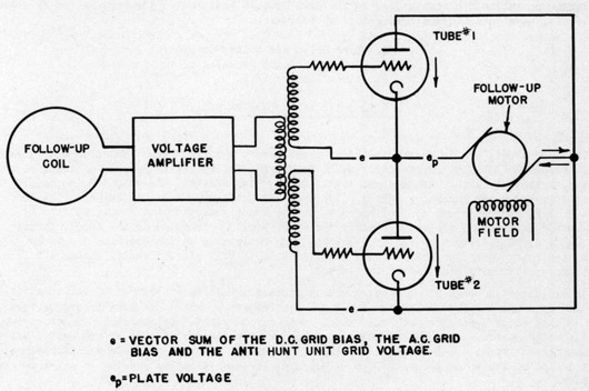
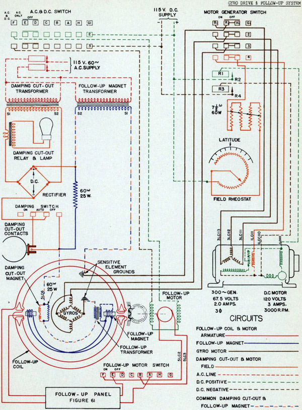
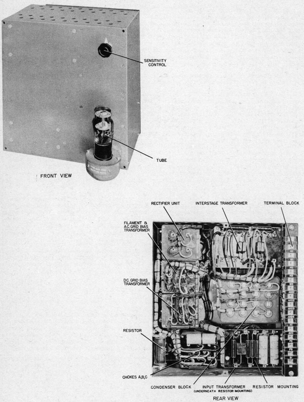
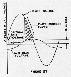 Figure 57 represents the condition which arises when an alternating potential is connected between plate and filament, and when the grid potential varies as shown by the curve marked "A.C. Bias Voltage". As long as the grid is more negative than its critical value, no plate current flows, even though the plate voltage rises to a high positive value. When the grid reaches a certain potential, the tube becomes conducting. A heavy plate current flows with a small voltage drop in the tube. When the plate potential falls to a value insufficient to keep the gas ionized, the tube once more becomes non-conducting.
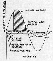 An electrodynamometer type galvanometer, having one winding connected to the 60-cycle supply, and the other to the lower winding of the interstage transformer, indicates the proper operation of the rectifier tubes. If the azimuth follow-up coil is displaced to a lower card reading than is correct, a signal voltage is set up by the follow-up coil and amplified by the 6A6 tube. The rectifier circuit wiring is such that tube #1 operates to increase card readings and tube #2 operates to decrease card readings. In this case, the phase of the amplified voltage would be such that tube #1 would operate to bring the card to its proper position, and tube #2 would not function. The meter would then read "Tube #1 On - Tube #2 Off". Displacement of the coil to a higher card reading causes tube #2 to operate and the meter to read "Tube #2 On - Tube #1 Off". Thus, by indicating which tube should be "On" and which should be "Off", the meter serves to point out broken or defective tubes.
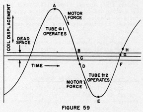 When toe follow-up coil is displaced from its neutral position, a voltage is induced in the interstage transformer secondary winding. This voltage added to the alternating bias potential has the effect of shifting the phase and changing the magnitude of the latter as illustrated in Figure 58. When the phase shift is in the direction shown, plate current flows through a larger than normal position of the cycle, causing the follow-up motor to run. When the follow-up coil is displaced in the other direction, the signal voltage from the amplifier reduces the grid potential during the half cycle in which the plate voltage is positive and no current flows through this tube.
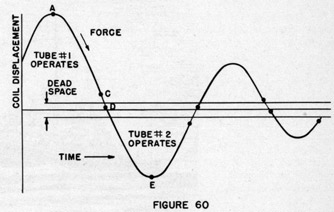 Since the variation in grid bias produced by the anti-hunt unit is nearly 90° out of phase with follow-up coil displacement, the effect as the coil nears the neutral position is to increase the negative bias on the operating tube causing it to become inoperative sooner than it would without the anti-hunt unit. Thus the point C, Figure 59, is shifted to the position shown in Figure 60. The "cut-in" point D is shifted in the same direction because the grid bias of the tube which is about to operate is made more positive.
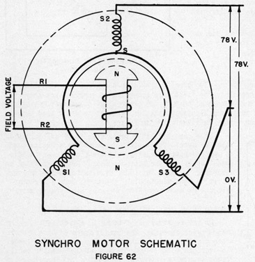 When it is desired to change the position of the rotor, to which the repeater card is attached, it is only necessary to change the voltages between the stator leads, so that the resultant magnetic effect of the three coils is along the new desired axis. The rotor will then align itself with its poles on this new axis.
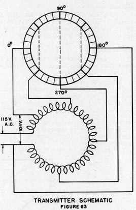 sinusoidal, as shown in Figure 64. The voltage between the 0° segment, which is painted blue, and any other bar α ° away is:
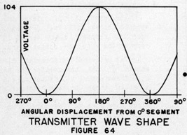 Each repeater cable terminates at a switch on the repeater panel. This switch connects the armature leads to the transmitter brushes, and the field to the single-phase supply on the control panel. Leads are fused as described on page 46. Only five switch poles are required by the single dial repeaters, but all repeater switches are made to control at least two synchro motors.