Gyro-compass Mark XIV, Mod. 1, 17-1400D, 1944, is a service manual for the most widely built gyro of WW II. This gyro was used on pretty much any ship that did not have automated fire control.
In this online version of the manual we have
attempted to keep the flavor of the original layout while taking advantage
of the Web's universal accessibility. Different browsers and fonts will cause
the text to move, but the text will remain roughly where it is in the original
manual. In addition to errors we have attempted to preserve from the original
this text was captured by optical character recognition. This process creates errors that are compounded while encoding for the Web.
Please report any typos, or particularly annoying layout issues with the Mail Feedback Form for correction.
SPERRY GYROSCOPE COMPANY, INC., MANHATTAN BRIDGE PLAZA, BROOKLYN, NEW YORK
I
SPERRY GYRO-COMPASS
FOREWORD
1. The purpose of this book is to enable the ship's personnel to operate and maintain their Gyro-Compass in a satisfactory and economical manner. If the basic principles of the Compass are understood and the rules laid down for operation, care and maintenance are followed carefully, the instrument should give satisfactory service for many years. Normal replacements, due to wear, will be necessary from time to time. Most of these replacements may be made by the Compass operator, following the instructions contained in this book. But the operator should not attempt to make any repairs or adjustments other than those noted in the text, otherwise he may seriously affect the adjustments and balances of the compass. It will be found more economical to have a Gyro-Compass Service Engineer make any major adjustments, overhauls, etc. The Sperry Gyroscope Company, Inc. maintains a staff of expert Service Engineers ready to render quick and efficient service in any port in the United States. A list of service stations will be found at the end of this foreword. If it is necessary to engage a Service Engineer, time and money will be saved by stating in your request for service the nature and cause of the trouble.
2. Basically the Compass is much like the very popular Mk. VI and VIII Compasses, of which over 1000 have been placed in service on ships representing almost every maritime nation in the world. Many improvements in design are present in the new compass but since they are too numerous to detail here, only a few outstanding changes will be mentioned.
3. The binnacle is designed to support the Compass in such a manner that the entire unit is shock-proofed. The doors are large, permitting free access for oiling and cleaning.
4. The mercury ballistic is cast in one piece so as not to be subject to distortion. The mercury tubes are made of stainless steel.
5. The follow-up system for the Compass is the a-c amplifier type. The great advantage of the Amplifier Unit over the trolleys and contactors, formerly used, is that it permits much smoother and more accurate transmission of the Master Compass readings to the repeater compasses. Its use also eliminates any rolling or sliding contact between the sensitive and phantom elements. This serves to lessen friction about the vertical axis of the sensitive element and assists in improving the accuracy of the compass. Furthermore, maintenance requirements are minimized.
6. In order to secure constancy of balance, all parts are made to have the utmost rigidity, thus balances once made are permanent.
7. Special attention has been devoted to ruggedness, simplicity, and accessibility of construction. This is considered specially important for the proper maintenance of a compass equipment aboard ship.
8. The Mark XIV Gyro-Compass Equipment consists of the following groups of units:
(a) Master Compass, by which the true north reading is gyroscopically discovered and maintained.
II
(b) Repeater Compasses, which receive and indicate the true heading transmitted electrically from the Master Compass.
(c) Course Recorder, which also receives the true heading electrically from the Master Compass, and makes a continuous record of the heading on a moving strip of paper.
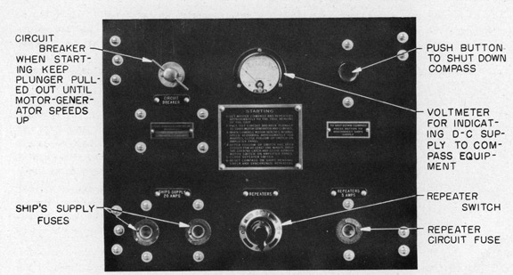
(d) Control Panel, for governing the electrical operation of the system and for ascertaining the running condition by means of a suitable meter.
(e) Voltage Regulator, to maintain constant the ship's supply to the motor-generator.
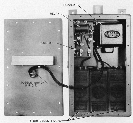
(f) Alarm Unit, for indicating failure of the ship's supply.
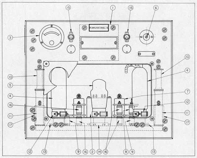
(g) Amplifier Panel, for controlling the follow-up system.
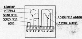
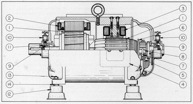
(h) Motor-generator, which converts the ship's d-c supply to a-c for energizing the Compass equipment.
9. Items a and b are treated in this pamphlet; likewise d, e and f are treated in another pamphlet. The remaining items are treated separately. The separate pamphlets are designed to be bound within one cover for convenience.
1. NOTE: A discussion of the fundamental principles of the gyroscope is contained in the Appendix to this text.
SENSITIVE ELEMENT
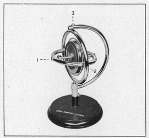
2. A gyro must be mounted so that it has 3 degrees of freedom. This is accomplished in the Sperry Gyro-Compass as described in the following paragraphs.
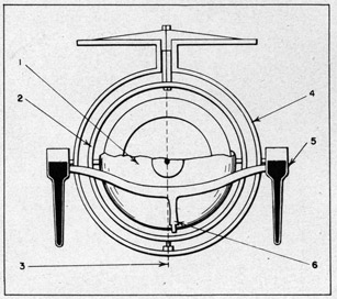
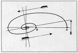
3. The gyro wheel is mounted on ball bearings in a case so that the wheel is free to turn about its SPINNING AXIS. See figure 1. Since the axle of the gyro aligns itself with the meridian we may speak of the north end and the south end of the axle. Carrying this terminology further, we refer to the north and south ends of the gyro rotor case, and the east and west sides of the case.
4. The case is provided with studs aligned horizontally on the east and west sides. These studs rest in bearings in the vertical ring. Refer to figure 2. This provides the gyro and ease with freedom about the HORIZONTAL AXIS.
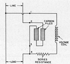
2
5. The vertical ring is provided with ball bearings aligned in the vertical axis of the Compass. This provides the gyro with freedom about the VERTICAL AXIS. The vertical bearings referred to do not actually support the vertical ring and hence they are called the (upper and lower) guide bearings. The actual weight of vertical ring, case and gyro is borne by a group of wires called a suspension. The reason for this is discussed under PHANTOM ELEMENT.
6. From paragraphs 3, 4, and 5 it can be seen that the gyro is mounted with the necessary 3 degrees of freedom. The gyro
wheel, its case, the vertical ring and the suspension constitute the north-seeking assembly of the Compass and are collectively known as the sensitive element.
7. Because the sensitive element is the north-seeking part of the Compass, it must be kept as free as possible from disturbing forces. The whole Compass is mounted in its binnacle on a gimbal system so that it may hang undisturbed by the rolling and pitching motion of the ship. Due to any number of causes the Compass might start swinging on its gimbal supports and thus be subjected to a disturbing force called the "pendulum effect". This effect arises from the fact that any weight swinging back and forth
as a Pendulum will turn so as to align its longest axis in the plane of the swing. In order
to give the sensitive element the effect of a sphere so that it has no "longest axis" and
thus not be subjected to the disturbing pendulum effect, certain weights are added to the
vertical ring. These weights are called COMPENSATOR WEIGHTS (see figure 2). They are accurately positioned on assembly at the factory and from the above it can be seen that THE SETTING OF THE COMPENSATOR WEIGHTS MUST NOT BE DISTURBED.
PHANTOM ELEMENT
8. As explained in the preceding, the sensitive element is the north-seeking element of the Compass. For this reason it must be mounted so as to be free to turn about a vertical axis in order that the gyro axle may align itself with the meridian. The mounting must also be arranged so that the sensitive element will not be carried away from the meridian as the ship turns beneath it. Any bearing friction, while the sensitive element turns (with respect to the binnacle) about a vertical axis, would cause a disturbance of the Compass. A practically frictionless method of mounting the sensitive element must be used. The method employed in the Sperry Gyro-Compass is explained in the following paragraphs.
3
9. It has already been said that the suspension supports the sensitive element. The top of the suspension is secured to the top of the phantom element (refer to figure 3). As the sensitive element is turned in azimuth (i.e., about the vertical axis) it would tend to twist the suspension. However, the phantom element is also arranged so that it can turn about the vertical axis and, by means of the follow-up system, is made to follow every movement of the sensitive element. This system of support supplies a practically frictionless mounting of the sensitive element. The manner in which the phantom is made to follow the sensitive element is described under FOLLOW-UP SYSTEM.
10. Since the phantom element is kept accurately aligned with the sensitive element, the former provides a convenient place to mount the compass card. Reference to figure 3 shows the location of the compass card, at the top of the phantom stem.
11. The phantom element, which consists primarily of a ring attached to a tubular piece called a stem, is supported by the spider element (figure 5). Ball bearings, called stem bearings, keep the 2 elements aligned and permit the former to turn freely with respect to the latter. The phantom is supported from the hub of the spider on a roller thrust bearing.
MERCURY BALLISTIC
12. The mercury ballistic (figure 4) is sometimes referred to as the control element.
13. The ballistic is suspended on horizontal studs fitted into ball bearings in the phantom ring and is attached to a bearing on the bottom of the gyro case by means of an arm called the link arm. The
bearing referred to is called the link bearing and is offset .170" to the east of the vertical axis of the case. See Appendix for a discussion of the principle involved.
4
14. As shown in figure 4, the 2 reservoirs in the east side of the mercury ballistic are interconnected by stainless steel tubes. The west pair is similarly connected. Each
pair of reservoirs contains 8 ounces of mercury.
15. The mercury ballistic is designed to be non-pendulous with respect to the horizontal axis. (Refer to para. 37 in the Appendix.) The balance weights are mounted on studs on the reservoir covers. Care must be taken not to alter or interchange these weights.
SPIDER ELEMENT
16. The spider element (see figure 5) is mounted on the gimbal system of the binnacle on athwartship trunnions. It carries (a) the azimuth motor which drives the phantom element to follow the sensitive element (see FOLLOW-UP PANEL), (b) the transmitters for operating the repeater compasses (see TRANSMISSION SYSTEM), (c) the speed and latitude corrector, and (d) the lubber ring.
17. The spider consists of a main frame, designed to bear the weight of the phantom and sensitive elements. The construction of the frame maybe seen in figure 5. A detachable lubber ring is carried on the rim of the spider frame. This ring carries an adjustable lubber line plate which is engraved with a lubber line against which the compass card is read. The correctors mentioned are mounted on the spider but are connected to the lubber ring so as to cause the latter to move as required. The corrections in the compass indication, as solved by the corrector mechanisms, are thus introduced into the Compass by shifting the position of the lubber ring. The transmitters for the repeater system, also mounted on the lubber ring, introduce the compass correction into the repeater compasses automatically.
18. The speed and latitude corrector (figure 5) is designed to compensate both the Master Compass and the repeater compass for the speed and latitude error. The correction for speed and latitude error could be set into the compass periodically, except that it varies as the cosine of the course and inversely as the cosine of the latitude. Therefore, some means of inserting a correction automatically for all changes in course must be used. A groove called the cosine cam is cut into the bottom of the azimuth gear on the phantom element. This cam is designed to move the corrector mechanism the proper amount to correct the compass readings for all changes in course. Changes of speed ( over 3 knots)
5
and latitude (over 3°) are set in manually. The corrector mechanism is shown schematically in figure 6. Roller 59 rides in the cosine cam which is cut into the lower side of the azimuth gear. As the Compass turns in azimuth, the cam causes arm 60 to move. Arm 60 constitutes a bell crank which moves arm 62 about adjustable pivot 63. This motion is imparted in turn to arm 64 through pivot 65. Arm 64 moves a pivoted block 66 which is attached to lubber ring 45. Thus the lubber ring is caused to move, as the ship changes course in a given latitude. It can be seen, from a study of figure 6, that for a given movement of arm 60, the amplitude of the resulting movement of the lubber line is determined by the position of pivot 63. The position of pivot 63 is a function of ship's speed and latitude. This position is determined by means of a latitude scale which moves across a plate engraved with speed curves as knob 57 is turned.
19. It will be noted that pivot 66, which shifts the lubber ring, is mounted on a block which may be translated by means of knob 58. This arrangement permits the correction for the tangent latitude error
to be superimposed on the speed correction. An auxiliary latitude scale enables this correction to be set in accurately.
BINNACLE
20. The binnacle supports and provides a protective housing for the Compass. It is provided with a gimbal system within which the Compass is suspended so that the Compass may hang vertically regardless of the ship's motion, within limits of 60° roll and 20° pitch.
21. To prevent violent swinging of the Compass when the ship is in heavy weather, dampers are provided on the gimbal system. See page 16 for description and maintenance.
22. The entire Compass is shock-mounted in the binnacle to absorb ship vibration. This is done to protect the Compass, moving parts from excessive wear which might result from undue vibration.
6
23. The sides of the binnacle open on hinges to provide convenient access to the Compass. The top may be removed when necessary.
24. Two lamps, connected in parallel, are provided in the binnacle for illumination. A switch and terminals are provided also in the binnacle to connect the lamps to
the lighting system of the Compass compartment.
GYRO-DRIVE SYSTEM
25. The gyro-drive system links the ship's supply to the gyro wheel.
26. The Compass gyro wheel is driven by a 3-phase induction motor. The rotor of the induction motor is a part of the gyro wheel, while the stator is attached to the gyro case. This motor is energized by a 3-phase, 210-cycle, 50 volt a-c supply. The method of obtaining this supply is described in separate pamphlets entitled "Control Panel" and "Motor-Generator".
27. The supply is lead to the binnacle terminal block, then to the spider terminal block, through the slip-rings mounted on the stem of the phantom ring, across to the vertical ring, down the east "side" of the vertical ring as far as the horizontal axis of the case, then across to the case and the gyro-drive motor.
28. This circuit has been lead from the source of supply to the gyro motor in the manner described so that the balance of the Compass will not be disturbed. Where the leads pass from phantom element to vertical ring, and from vertical ring to rotor case, extra flexible conductors are used so as not to exert a torque on the sensitive element. THE POSITION OF THESE LEADS SHOULD NOT BE DISTURBED BY THE COMPASS OPERATOR.
TRANSMISSION SYSTEM
29. The transmission system is used to transmit the heading of the Master Gyro-Compass to all repeater compasses, and to the Course Recorder should the ship be supplied with this instrument.
30. The system operates on 70-volts d-c and consists of a transmitter attached to the lubber ring of the Gyro-Compass (see figure 5), connected electrically with the repeater motor mounted in the casing of each repeater compass.
31. The transmitter consists mainly of a commutator and a roller carriage. The
commutator comprises 12 segments secured to the lower end of the transmitter frame. The
roller carriage is secured to a shaft free to turn within the transmitter frame and the shaft is geared to the azimuth gear on the phantom element. A contact arm, held against the roller carriage by a spring, provides a means to hold the carriage in place and to connect it to the 70-volt d-c supply.
32. It has been previously stated that the compass card is attached to the stem of the phantom element, and that attached to the stem below the compass card is the azimuth gear (see figure 3). The gear on the transmitter roller carriage is meshed with the azimuth gear so that the latter will drive the roller carriage of the transmitter as the phantom element moves in azimuth.
7
FIGURE 7
SCHEMATIC DIAGRAM
SHOWING HOW THE REPEATER COMPASSES ARE OPERATED FROM THE MASTER COMPASS
33. The repeater compass consists of a small d-c step-by-step motor mounted in a casing. The motor drives a compass card which is read against a lubber line secured to the casing.
34. A lamp for illuminating the repeater card is mounted under the repeater motor. The repeater bottom cover may be removed for access to the lamp. A dimmer switch for controlling the brilliancy of the repeater will be found in the repeater stand.
35. Figure 7 shows the electrical connections between transmitter and repeater. The leads marked "Supply Line" are connected to a 70-volt d-c source: The 70-volt supply is obtained by reducing the ship's 115-volt d-c supply by means of a carbon pile regulator or a series resistor (see circuit diagram in Control Panel instruction book). If the ship's supply is 220 volts, the 70-volt supply is obtained from a d-c generator which is incorporated in the compass (220 V.) motor-generator set.
36. Lead 4 (figure 7) carries the positive leg of the circuit to the transmitter when the circuit breaker and repeater switches are closed on the compass panel. At the transmitter the positive leg is directed to lead 1, 2 or 3 depending on the position of the roller carriage. The circuit then passes back to the panel, through the repeater switch to the
correspondingly numbered coils on the repeater motor. The return to the panel is made through lead 5 which is connected through a fuse and the repeater switch to the common return for the various compass circuits.
8
37. Resistors for loading the transmitter, and condensers for quenching sparking as the roller carriage passes from segment to segment, are connected in the circuit at the compass binnacle terminal block. See circuit diagram in the Control Panel instruction book.
FOLLOW-UP SYSTEM
38. The Gyro-Compass employs the a-c amplifier type of follow-up control. The
amplifier panel used is external to the Compass and is described in detail in a separate pamphlet entitled "Amplifier Panel". For convenience, the operation will be described briefly here.
39. A follow-up transformer is mounted on phantom element (figure 3) so as to
be normally aligned with an armature carried by the sensitive element. The transformer has 3 legs; the center leg is energized from one phase of the 210 cycle supply to the gyro motor, while the 2 outer legs are connected to the vacuum tube amplifier in such a way that when the transformer and armature are aligned, there is no signal to the amplifier. When the sensitive element moves away from the phantom element, the signal to the amplifier corresponds in direction and amount to the direction and amount of such movement.
40. The amplifier augments the input signal so as to control 2 rectifier tubes, which energize the azimuth motor armature. Since the field of this motor is continuously
excited from the d-c supply, the motor drives the phantom element so as to bring the transformer again opposite the armature on the sensitive element. Then the input to the amplifier ceases and the motor stops.
41. Because of the sensitivity of the follow-up control, in actual operation the phantom element never becomes more than slightly displaced from the vertical ring, and upon being so displaced is instantly brought back into alignment.
RADIO FILTER
42. An electrical filter, comprising chokes and condensers, is usually provided within the binnacle so as to suppress any interference with the radio equipment on the Ship.
9
SECTION II
- OPERATION -
PREPARING TO START
43. Preparations should be begun preferably at least 4 hours before the Compass is required for service.
44. Make certain that all supply switches are open.
45. Unlock binnacle top cover, open one door and make sure that vertical ring and rotor case locks are applied.
46. Take hold of both sides of phantom and vertical rings and turn them slowly until compass card indicates approximate heading of ship. The Compass should never be turned in azimuth, with the power off, by pressure on compensator weights or mercury ballistic.
47. Check height of oil on oil well windows. Make sure that oil level is just
even with center of dot on window and that oil level is the same on both sides of Compass.
48. Test alarm by throwing switch on alarm unit for a second or so, to make sure relay functions.
49. Adjust speed and latitude and auxiliary latitude correctors to proper setting. (See paragraphs 67 to 69.)
STARTING COMPASS
50. Throw control switch on control panel to ON.
51. Pull out circuit breaker plunger on control panel to energize motor generator. Hold plunger out by hand until motor-generator speeds up (in about 5 seconds).
52. When starting alongside a dock, wait until rotor is up to speed (in approximately 10 minutes), then turn on follow-up switch on amplifier panel. (When starting up at sea, release the rotor case and vertical ring locking latches immediately and steady the rotor case by hand until rotor is up to speed.)
53. Wait one minute for rectifier tube filaments to heat up.
54. Release rotor case and vertical ring locking latches.
55. Turn ON azimuth motor switch at amplifier panel.
56. Synchronize all repeaters to the same heading as the Master Compass, and then close all repeater switches.
57. Turn switch at alarm unit so as to silence alarm.
10
58. Reset Compass on ship's heading by pressing down on one or the other of the rotor case bearing housings, and if necessary level the rotor by pressing against the vertical ring until bubble is on normal settled position. Check repeaters, and synchronize if necessary.
SETTING COMPASS ON MERIDIAN WHEN DIRECTION OF NORTH IS KNOWN
59. After Compass is up to speed and operating normally, precess Compass by pressing on top of either rotor case bearing housing until zero on compass card points true north, at which time the card will indicate the true heading of the ship. Then level the case by bringing bubble to normal settled position and allow Compass one hour to settle.
SETTING COMPASS ON MERIDIAN WHEN DIRECTION OF NORTH IS UNKNOWN
Within 2 Hours After Rotor Has Come Up to Speed
60. Level the case; approximately 21 minutes later level it again; approximately 21 minutes later level it a third time. The Compass then will indicate approximately the
true meridian. When the bubble remains at its normal operating position, the Compass has settled on the true meridian.
Within One Hour After Rotor Has Come Up to Speed
61. Level the case and observe rate of travel of rotor case level bubble, in minutes of arc for any convenient period of time (say 3 minutes). Also note direction of movement.
62. Divide number of minutes of arc through which bubble traveled by number of minutes of time allowed for the test. Multiply this quotient by the constant 5. The product will give approximate number of degrees deflection from meridian.
63. If bubble travels to south, Compass should be precessed to east, and if bubble travels to north, Compass should be precessed to west. Amount of precession should be equal to number of degrees obtained in preceding paragraph. Thus, if bubble moves to south at
rate of 6 minutes of arc in 2 minutes of time, when Compass heading was 125°, then north end of Compass is pointing approximately 6/2 x 5 = 15° west of the meridian and it should be precessed this number of degrees to the east, or to 125° - 15 = 110°.
64. Level the case, again observe bubble movement and make a finer correction if and when necessary. When bubble movement has become less than one minute of arc in 5 minutes of time, Compass should be within one degree of the meridian. The foregoing rule is
approximately accurate for deflections up to about 50° in latitudes between 0° and 60°.
65. Care should be taken that Compass is not started exactly 180° off the meridian, as bubble will travel very slowly when Compass is heading in such a direction.
66. The settling position of the gyro axle relative to the meridian is reached when the bubble finally occupies its normal settled position in the level. In case the normal settled position of the bubble is not central, when Compass is settled on the meridian, its normal settled position should be recorded and used in making the above setting.
11
SETTING THE SPEED AND LATITUDE CORRECTOR
67. When Compass is in operation, the corrector should be set for the approximate speed and latitude of the ship. These settings need not be changed for small variations in speed and latitude, but should be kept within 3 knots and 3° respectively.
68. To set corrector, turn knob 57 (figure 1) until the scale line corresponding to the ship's latitude on the movable latitude bar intersects the curve representing the ship's speed on the speed plate across which the latitude bar is movable.
SETTING THE AUXILIARY LATITUDE CORRECTOR
69. To set the auxiliary corrector, turn knob 58 (figure 1) until line engraved on lubber ring coincides with approximate local latitude marked on adjustable block of corrector.
IF ALARM SOUNDS DURING NORMAL COMPASS OPERATION
70. A momentary failure of the supply current will cause buzzer to sound until the supply is restored, and in such case the accuracy of the Compass will not be affected. It is advisable, however, to check repeaters with Master Compass after any momentary failure of the supply.
71. If alarm continues to sound, the current failure evidently is more than temporary. Turn switch OFF to silence buzzer. Examine control panel immediately. The circuit breaker is adjusted to open approximately 5 seconds after ship's supply fails. If, on examination, the circuit breaker is found open, repeat instructions for starting Compass at sea. Check Master Compass and repeaters.
STOPPING COMPASS
72. Open repeater switches.
73. Turn alarm switch to silence buzzer.
74. Turn OFF azimuth motor switch.
75. Turn OFF follow-up switch.
76. Throw toggle switch on control panel to OFF. This de-energizes the circuit breaker coil and causes circuit breaker to open.
77. If stopping Compass at sea, during heavy weather when considerable motion is imparted to the Compass, steady rotor by hand until it stops, then lock it with locking latches. If stopping at dock, there is no need of supporting rotor by hand; it may be locked immediately.
78. Inspect equipment and clean same if convenient. The equipment can best be
cleaned while it is still warm.
12
NOTES
79. Under normal operation, the rotor case is uncomfortably hot to the bare hand. This should occasion no alarm, as the normal operating temperature is approximately 45° C higher than room temperature. Keep oil level even with center of dot in oil-well windows at each end of rotor case.
80. Keep binnacle doors closed and cover locked whenever the Compass is left unattended. Allow no unauthorized person to tamper with it at any time.
81. With ships having 220-volt d-c supply, the operating instructions are somewhat different from the preceding. Refer to separate instruction pamphlet provided with 220-volt control panel.
13
SECTION III
- MAINTENANCE -
82. A summary of inspection, cleaning and oiling instructions is presented herewith. Further details will be found in the Amplifier Panel, Control Panel, and Motor-Generator pamphlets.
ROUTINE INSPECTION
EACH WATCH
83. Check repeaters with Master Compass to be sure repeater system is functioning properly. If supply fails for any reason be sure to check and, if necessary, synchronize
repeaters as soon as supply is restored.
84. Check Compass by azimuth observation if possible.
85. The speed and latitude corrector and auxiliary latitude corrector should be properly reset whenever changes of speed and latitude make resetting necessary, as advised in paragraph 67 under OPERATION.
86. Inspect Compass to guard against any abnormal condition of operation.
EACH WEEK
87. Check alarm unit by turning switch on alarm unit and noting that buzzer sounds.
88. Check all electrical connections to make sure they are tight, clean and free from oil.
89. Clean and oil parts as indicated on charts, pages 18-21.
EACH MONTH
90. Polish the glass over the repeater card. Clean the repeater stand if it is
in an exposed position.
91. Check alignment of azimuth motor brushes as described on page 15.
92. Clean and oil parts as indicated on charts, pages 18-21.
CARE OF MERCURY BALLISTIC
93. The mercury ballistic reservoirs are ventilated through small holes in the reservoir tops so that the mercury will not become air bound as it flows from one reservoir to the other. Due to the presence of this air, a certain amount of oxidation of the mercury takes place. This takes the form of a film on the surface of the fluid and eventually the film will retard its free movement. For this reason the mercury should be checked about every
14
3 months to make sure that it flows freely. For economy of up-keep and maintenance, instructions are given here so that the ship's personnel may inspect and, if necessary, change the mercury. It must be borne in mind, however, that the mercury ballistic is the controlling element of the Compass and that care must be exercised in handling and adjusting it. The instructions given herein must be followed exactly.
94. To observe flow of mercury in ballistic, remove tops of reservoirs, unlock case and tilt ballistic from side to side. This must be done only when gyro is not running. The mercury should flow freely from one reservoir to the other. The appearance of film on the fluid is not harmful, provided the mercury flows freely. If it does not flow freely,
proceed as described below. If it does, replace reservoir tops, but be very careful not to interchange them when replacing.
95. If the mercury needs changing, remove ballistic from Compass as described on page 15. Pour out the old mercury, keeping that removed from each set of reservoirs in separate non-metallic containers.
96. Carefully wipe out reservoirs with a clean cloth moistened with carbon tetrachloride. (Do not use gasoline.) Make sure that all carbon tetrachloride is evaporated
from the parts, before replacing the mercury. Clean out mercury tubes with tube (pipe)
cleaners, provided in the spare parts box. After using cleaners, blow out tube to remove
any lint.
97. Carefully strain mercury removed from west reservoirs through fine cheese cloth until it is clean and bright. Then pour this mercury back into one of the west reservoirs, pouring in a continuous stream so that no air bubbles are trapped in the tube. Repeat process for fluid removed from east reservoirs. If any mercury is spilled during this process, BOTH sets of reservoirs should be emptied and refilled with fresh mercury found in spare parts box. Each bottle contains 8 ounces of mercury. Pour 8 ounces into each set of reservoirs as described above. After refilling ballistic with mercury, replace reservoir tops, making sure not to interchange them. Replace ballistic on Compass as described on page 15.
ADJUSTMENTS AND REPLACEMENTS
TO REMOVE LOST MOTION IN TRANSMITTER
98. Turn lost motion adjusting knob (figure 1) all the way counterclockwise.
TO REPLACE TRANSMITTER ON LUBBER RING
99. Position the compass card so that it reads to an exact degree. Card may be
turned slight amount required by turning azimuth motor shaft.
100. Turn lost-motion adjusting knob (figure 1) all the way counterclockwise to take up, as much as possible, lost motion in transmitter carriage drive.
101. Place roller carriage on contact segment 1.
102. Put transmitter in place as shown in figure 1 and make sure its gear meshes properly with azimuth gear. Insert mounting screws loosely. With card on an even degree,
15
shift transmitter until roller is again positioned on segment 1, if it was moved while attaching transmitter. Then take, up tightly on mounting screws.
103. Start Compass arid repeaters. Check repeater readings and synchronize with
Master Compass. If, when compass card is on an exact degree heading, repeaters do not exactly synchronize, loosen transmitter mounting screws and tap the transmitter so that it moves slightly on the elongated mounting holes until repeater readings match exactly with Compass reading.
TO REMOVE AND REPLACE MERCURY BALLISTIC
104. Remove 2 screws which attach link arm (figure 4) to ballistic frame.
105. Carefully lower link arm so that it slides away easily from link bearing on bottom of case.
106. Back off the mercury ballistic bearing studs (figure 4) until they are clear of their bearings. Lower ballistic frame until it is clear of Compass and remove from binnacle.
107. When replacing ballistic, proceed in reverse order from above. The west bearing stud is pinned to its locknut and should be screwed in as far as it will go. The east stud should be adjusted so that ballistic has about 0.005" side shake when Compass is cool. The locknut then should be taken up so that stud is locked in place. If possible, use feeler gauge to determine the proper side shake. If gauges are not available, the stud may be replaced properly by making a mark on phantom ring in line with slot in stud before removing ballistic. When replacing ballistic, take up on stud until it is tight, then back off until slot is in line with the mark. If this method is used, take care not to back off 1/2 turn too much. When replacing ballistic, make sure that north side of ballistic frame is on
north side of gyro case. A letter N is stenciled on north side of frame.
108. When replacing link arm, make sure it engages link bearing properly before attaching arm to ballistic frame.
TO ADJUST AZIMUTH MOTOR GEAR MESH
109. The azimuth motor may be adjusted in or out, with respect to the main gear, by means of the set screw and clamp screw on one end of the frame. It should be set so there is no lost motion between the azimuth gear and the azimuth motor pinion.
110. When making this setting the Compass should be slowly turned in azimuth by hand to make sure that it is free in all positions. There must be no binding or stalling
of the azimuth motor in any position about the azimuth gear.
TO ADJUST AZIMUTH MOTOR BRUSHES
111. The azimuth motor brushes are clamped in holders mounted on the azimuth motor frame. The brushes should be adjusted so that, when they are seated on the commutator, the brush holders are parallel to each other. To obtain this condition, loosen brush clamping screws, adjust brush and reclamp. When holders are parallel, the distance from commutator to holder is approximately 1/4 inch. When brushes are readjusted, sand them into fit commutator.
16
TO ADJUST LUBBER LINE PLATE
112. This plate is provided on the Compass to compensate the reading for small permanent errors. Do not attempt to remove such errors by twisting the suspension.
113. The compensation is made as follows: Suppose the Compass reading is 278 and it has been definitely established (by sun azimuths, bearings, etc.) that the Compass is 2° low. Simply loosen thumb nuts which clamp lubber line plate to lubber ring and shift
lubber line so that reading is 280. Reclamp plate. It is then necessary to change each repeater reading so that the repeaters are synchronized with the Compass. NOTE: If the plate is moved only a fraction of a degree, the repeater headings should be changed by loosening the transmitter on the Compass and shifting it as necessary to make repeater reading correspond to Compass reading.
ROLL DAMPER
114. A dashpot damper (figure 8) is provided at the after gimbal bearing to restrict movement of the Compass about the fore-and-aft axis. The unit comprises two dash-pots, each containing a piston and a quantity of oil. Movement of the pistons, due to swinging of the Compass about the axis mentioned, is opposed because of the restricted oil flow.
115. The action of the dashpot damper is entirely automatic; no adjustment of the unit should be attempted.
116. The dashpot dampers should be kept filled with compass rotor oil to a point one inch below the top of the pots. The level can be determined by pushing a small piece
of wire through the holes in the cap. If dashpots are too full, the oil will run out when the ship is rolling heavily. If the oil level drops below the piston, the dashpots will be useless. The level should be checked each month and new oil added if necessary.
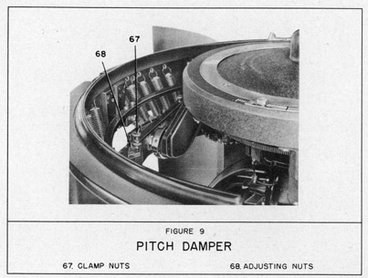
PITCH DAMPER
117. A friction damper (figure 9)is used to restrict swinging of the Compass about the athwartship axis. The damper comprises an adjustable friction brush riding on a cam.
To obtain proper damping action, proceed as follows:
118. Loosen clamp nuts 67 (figure 9) and raise brush off cam far enough to insert a small piece of paper under brush.
119. Position adjusting nuts 68, keeping friction brush holder horizontal, so that when clamp nuts are taken up tight it is just possible to withdraw the paper without tearing it.
17
120. In heavy weather it may be necessary to take up on the damper to prevent the compass case from hitting the stops on the vertical ring. However, as soon as the weather permits, the dampers should be readjusted as described above. If this is not done, an error in the compass indication may result.
18
CLEANING CHART
GENERAL
AT MONTHLY INTERVALS - Clean inside of binnacle and all mechanical compass parts with a soft cloth moistened in carbon tetrachloride. Wipe dry after cleaning. Check all electrical connections to make sure they are tight, clean and free from oil.
The crocus paper referred to in these instructions is an extra fine, high grade abrasive paper. Do not use any other kind.
CAUTION: When cleaning or oiling the Master Compass, be careful not to disturb
the 3 flexible leads between the phantom ring and the vertical ring, and between the vertical ring and the rotor case.
MASTER COMPASS
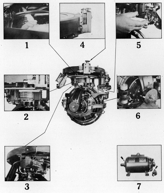
1 CORRECTOR COSINE CAM: MONTHLY - Clean out any hard deposit of grease and dirt.
2 COLLECTOR RINGS: MONTHLY - Clean with a strip of cloth (about 1/2 inch wide) moistened in carbon tetrachloride, drawing the cloth back and forth on each ring surface throughout about half its circumference. Then turn compass 180° and repeat.
Polish with a dry strip of cloth in the same manner.
3 AZIMUTH MOTOR COMMUTATOR AND BRUSHES: MONTHLY - Wipe off commutator brushes and brush-arms with a soft cloth moistened in carbon tetrachloride. Polish commutator with a clean, lintless cloth, holding it against the commutator with the index finger while turning the damping weight back and forth with the other hand.
4 CORRECTOR: MONTHLY - Wipe excess oil from the outer surfaces of the corrector and from the bottom of the lever arm.
5 TRANSMITTER: MONTHLY - Snap contact arm in to the vertical position and remove roller carriage. Clean the contact surface of the segments with a small piece
of folded crocus paper. Insert the edge of the folded crocus paper between adjacent segments to remove carbon dust. Clean the roller carriage and the interior of the carriage compartment with a soft cloth moistened in carbon tetrachloride, and wipe out with a dry cloth. NOTE: It is not necessary to remove the transmitter from the lubber ring, for cleaning. CAUTION: The Compass must not be turned in azimuth while the contact arm is in the vertical position.
6 ROTOR BEARING HOUSING AND OIL WINDOW: EVERY 3 MONTHS - Clean when renewing
rotor bearing oil. After the old oil has been pumped out, remove the bearing housing end plate, shown by the upper arrow. Take out the attaching screws and screw two of them into the two threaded holes in the edges of the plate to force the plate and gasket off the housing. Clean the oil window with a soft cloth moistened in carbon tetrachloride and held on the end of a thin hardwood stick. Do not unscrew the oil window from the bearing housing. If the oil wicks are clogged with sediment, remove the assembly by taking out the 4 small screws that hold it in place. Clean the assembly thoroughly in carbon tetrachloride and brush the wicks off with stiff brush. Be sure all carbon tetrachloride has evaporated from the wicks before replacing them. Clean the interior of the housing with a small piece of cloth saturated with carbon tetrachloride. Use the thin hardwood stick to force the cloth around the interior of the housing to remove all oil sediment. Dry out interior with a clean cloth to remove all traces of carbon tetrachloride before replenishing with oil. (See paragraph 13 under Oiling.)
19
7 COMMUTATOR AND BRUSHES: MONTHLY - Wipe off the commutator surface and brushes
with a soft cloth moistened with carbon tetrachloride. When the motor-generator is stopped, brush the space between the commutator bars axially with a small stiff brush. Wipe off with a soft dry cloth. Be sure that no particles of dust or dirt remain between the brush and commutator surface. To insure proper ventilation, brush the screened plates at each end of the motor-generator with a stiff brush.
20
OILING CHART
GENERAL
WEEKLY OILINGS may be omitted where such application would disturb the Compass. However, it is recommended that the interval between such oilings be not greater than 2 weeks.
Wherever oil is mentioned in these instructions, compass rotor oil is implied.
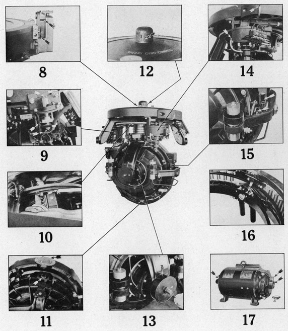
8 CORRECTOR: MONTHLY - Lubricate moving parts with a film of oil. Add one or two drops of oil to roller stud in cosine cam.
9 TRANSMITTER: WEEKLY - An oil hole at the top center leads to the upper shaft bearing. An arrow at the bottom points to the lower shaft bearing. A small
arrow above the one just mentioned points to the lost-motion device yoke rollers, within the transmitter. Two oil tubes, terminating at the top of the transmitter, lead to other bearings requiring lubrication. The top oil hole, the two arrows and the two tubes are painted red and are readily located. Apply two drops of oil to each lubrication point. MONTHLY -Coat gear surfaces with a light film of oil, using a camel's hair brush. Keep segments and roller carriage free from oil.
10 CORRECTOR COSINE CAM: MONTHLY - After cleaning the cosine cam groove, add a thin coating of the cup grease supplied in the spare parts box. Coat azimuth gear surfaces with a light film of oil applied with a camel's hair brush.
11 BALLISTIC LINK BEARING: WEEKLY - Add 4 drops of oil to the bearing and its
link (upper arrow). LOWER VERTICAL RING GUIDE BEARING: This bearing (lower arrow) is submerged in oil which need be changed only when the Compass is undergoing general overhaul.
12 PHANTOM STEM BEARINGS AND UPPER VERTICAL RING GUIDE BEARING: WEEKLY - Apply 10 drops of oil to each of the two oil holes underneath the suspension cap. Access is provided to these oil holes through holes in the cap.
13 ROTOR BEARINGS: AT WEEKLY INTERVALS inspect oil level on each side of rotor case and replenish if necessary to keep the oil surface level with center of
dot at center of glass window. EVERY 3 MONTHS renew the oil in each side of rotor case as follows: remove oil plug and pump out the oil with metal syringe provided in the spare part box. Remove the bearing housing end plate as described in paragraph 6 under Cleaning. Inspect the interior of the housing and the oil wicks. If wicks are clogged with sediment, remove assembly and clean as described in paragraph 6. Before filling oil reservoir clean interior of housing and oil window as described in paragraph 6. When reinstalling the oil wick assemblies make sure they are put back exactly as they were. The upper ends of the 3 wicks should touch the lower edge of the ball bearing inner race. The lower ends of the wicks should be coiled in the lower part of the housing so that the oil level will completely cover them. Replace the end plate, tightening the attaching screws evenly all around, and fill with oil through the oil plug hole to the center of dot in center of glass window.
14 AZIMUTH MOTOR: WEEKLY - The upper oil tube carries oil to the upper motor shaft bearing, and also to the upper and lower intermediate gear shaft bearings. The lower tube leads to the lower motor shaft bearing. Apply 6 drops of oil to the upper tube, and 2 drops to the lower tube. MONTHLY - Coat gear surfaces with a light film of compass rotor oil, using a camel's hair brush.
15 BALLISTIC BEARINGS: WEEKLY - Fill up the cup-type reservoirs on each side of the phantom ring with oil (upper arrow). HORIZONTAL ROTOR CASE BEARINGS:
WEEKLY - Move vertical ring to maximum out-of-alignment position with phantom ring and apply 8 drops of oil to hole in center of large nut containing the horizontal rotor-case bearings on each side (lower arrow).
16 GIMBAL BEARINGS: MONTHLY - The fore-and-aft and athwartship ball bearings are oiled by placing a few drops of oil on the studs where they enter the bearings. The two azimuth guide pins should be given a thin coating of cup grease.
21
17 MOTOR-GENERATOR: EVERY 3 MONTHS - Turn the grease cups down one full turn.
YEARLY - Remove bearings and clean them thoroughly in carbon tetrachloride.
After all trace of carbon tetrachloride has evaporated from bearings, repack them with cup grease of the kind supplied in the spare part box, and replace. To repack: coat ball bearings with a thin layer of grease. Place just sufficient grease in each bearing housing to cover the lower part of the ball bearing.
CAUTION: DO NOT OVER OIL
22
SECTION IV
PARTS LIST
INTRODUCTION
This Parts List contains all replaceable parts for the Sperry Mk. XIV, Mod. 1 Gyro-Compass and Accessories.
The parts are grouped by assemblies and sub-assemblies. A drawing of the assembly, and a list of the
parts giving the name, part number and quantity required are included for each assembly.
By means of a symbol each part is identified with the assembly drawing, and the description of the part. THE SYMBOL IS TO BE USED ONLY FOR IDENTIFICATION OF THE CORRECT PART NUMBER AND DESCRIPTION. THE PART NUMBER AND DESCRIPTION MUST ALWAYS BE USED FOR INQUIRIES AND ORDERS.
Letters are used as symbols in place of numerals where a separate drawing for the assembly has been prepared. Double letters indicate the assembly appears on the same sheet. Single letters indicate the assembly is shown on a separate sheet.
Standard size screws, nuts, washers, and pins are not assigned part numbers. On inquiries or orders the
dimensions in addition to the name must always be given.
ORDERING INSTRUCTIONS
Quick shipments and prompt replies to inquiries are possible
only when complete identifying information for parts is given.
Careful observance of the following points on inquiries or
orders is essential for prompt service.
1. Name the part and part number as shown in the list and state quantity desired.
2. Furnish the name plate data of the apparatus for which parts are desired.
3. State whether shipment is to be made by express, freight or parcel post.
1. The word "gyroscope" is of French origin -- a combination of two Greek words, "gyros", meaning tumor revolution, and "skopein", meaning to view, the literal translation of the two words being "to view the revolution" of the earth. The correct pronunciation of the word is with the g soft as in "gentleman". In the first syllable the y is long, as in "sky". Ro is pronounced like the "row" in rowboat, and scope to rhyme with "rope".
2. The reason the French have the distinction of originating the name gyroscope is because the great French scientist Leon Foucault was one of the first authorities on the subject of gyroscopic phenomena, having succeeded as early as 1852 in actually producing a gyroscope with which he could observe, with the aid of a microscope, the ceaseless onward movement of the earth's rotation.
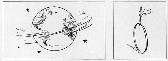
3. If the reader will permit one more slight digression, it might be well to remember (before we get down to serious business) that the sphere on which we live is in itself a mammoth gyroscope and that there probably would be no life at all on the earth if it did not revolve like a top, with the direction of its polar axis fairly constant. Otherwise the surface of the earth would be exposed to extremes of heat and cold with such rapidity that living organisms would not be able to survive.
DEFINITION AND PRINCIPLES OF THE GYROSCOPE
4. There is nothing mysterious about the gyroscope. Its actions, though they may appear at first to defy the laws of physics, in reality depend entirely upon Sir Isaac Newton's Laws of Motion.
5. Many of the toys we used to play with were based on gyroscopic principles. A spinning top is an elementary form of gyroscope, the "diabolo" -- once a popular object for pastime -- is another; so also is a hoop, for it will exhibit the characteristics of a gyro as long as it has sufficient motion to roll along the ground.
6. All of the practical applications of the gyroscope are based upon two fundamental characteristics, namely: "Gyroscopic Inertia" and "Precession".
2a
FIGURE 1a
The gyroscope has three axes of angular freedom.
7. Gyroscopic Inertia, or rigidity in space as it is sometimes known, is the tendency of any rotating body to preserve its plane of rotation. For example, a
hoop, when set in motion, will keep on rolling approximately in a straight line if undisturbed, instead of tipping over as it would if not revolving.
8. The second characteristic of the gyroscope -- Precession -- is also exhibited by the rolling hoop. If we wish
to change its direction of travel, we do not press against the rim at the front or back, but at the top -- as though we intended to tip it over about an imaginary horizontal axis. The hoop resists this
pressure and turns, instead, about a vertical axis which is at right angles to the axis about which the pressure was applied.
9. If we transform the hoop into a wheel, provide an axle for it, and mount the axle in supporting rings as shown in Figure la, we can obtain a true gyroscope, which is simply a spinning wheel or mass, universally mounted. Only one point -- the geometrical center of its supporting system -- is in a fixed position, the wheel being free to turn in any direction around this point. The wheel or rotor is free to revolve in its supporting ring about axis 1. The supporting ring is free to revolve in an outer ring about axis 2 which is always at right angles to the axis of rotation of the
FIGURE 2a
When spinning, the gyro exhibits
'gyroscopic inertia'
FIGURE 3a
The original plane of rotation
is maintained no matter how the
base is moved about.
3a
FIGURE 4a
Precession about the vertical axis.
FIGURE 5a
Precession about the horizontal axis.
wheel. The outer ring likewise is free to revolve in pivot bearings in a supporting frame about axis 3 which is always at right angles to the axis of rotation of the inner ring.
10. With this arrangement, the axle can be pointed in any direction without altering the geometrical center of the assembly. When such a wheel is spinning, it exhibits
exactly the same characteristics as the hoop, but does so without having to be rolled along
the ground. "Gyroscopic inertia" may be illustrated by spinning the rotor and placing it
in the position shown in Figure 2a. If the base of the gyroscope is tilted, as shown in
Figure 3a, the rotor, instead of tipping over as it would if not revolving, maintains its original plane of rotation. It will continue to do so, no matter how much the base of the gyro is moved about, as long as it continues to spin with sufficient velocity to overcome the friction between itself and its supporting bearings.
11. This characteristic is the result of the action of forces affecting the state of rest and motion of a gyroscope in the manner expressed by Newton's First Law of Motion, which states that every body continues in its state of rest or of uniform motion in a straight line, unless it is compelled by forces to change that state. This law as applied to a rotating wheel may be expressed by stating that a rotating wheel tends to maintain the direction of its plane of rotation in space and the direction of its axis in space.
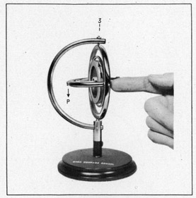
12. "Precession" may be illustrated by applying a force or pressure to the gyro about the horizontal axis as shown in Figure 4a. It will be found that the applied pressure meets with resistance and that the gyro, instead of turning about its horizontal axis, turns or "precesses" about its vertical axis in the direction indicated by the arrow P. Similarly, if we apply a pressure about the vertical axis, the gyro will precess about its horizontal axis as shown at P in Figure 5a. If there were a complete absence of inertia and friction about the precessional axis, the rate of precession would be such that the resistance of the
4a
gyro would be exactly equal to the applied pressure at any instant, and no movement from this pressure could ensue until the gyro had precessed so that its plane of rotation coincided with the plane of the applied pressure. Then the precession would cease and, with it, all resistance to the applied pressure.
FIGURE 6a
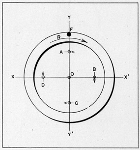
Gyro rotor shown in section. For the sake of clarity its mass is considered to be concentrated in four separate particles, A, B, C, and D.
13. A convenient way to remember the direction in which precession takes place is to regard the pressure as though it acted at a single point on the rim of the wheel, as indicated by the black dot in Figure 4a. This point will not move in response to the pressure, but a point 90 degrees beyond, in the direction of the wheel's rotation, will move away instead.
14. There you have the gyroscope in a nutshell, but inasmuch as the next step will be an explanation of the reason for precession, your may wish to ask a question or two at this point. You might like to
ask, for instance, why it is that of the many rotating objects with which you are familiar, some display gyroscopic phenomena and others do not. Why does a top exhibit gyroscopic characteristics while an engine flywheel, which also spins with high angular velocity, does not. Why does a rifle
bullet behave like a gyroscope while a windmill merely behaves like a windmill.
15. Gyroscopic properties are inherent in all rotating masses, but can best be observed in those which have the greatest amount of freedom about two axes in addition to the spinning axis. The top comes under the latter category. The engine flywheel, on the other hand, is limited to one angular axis of freedom -- its spinning axis. A rifle bullet may be likened to a gyroscope because it is free to revolve about two other axes, in addition to its spinning axis; therefore it exhibits gyroscopic inertia, tending to maintain a straighter line of flight than it would if not rotating. A windmill has freedom about its spinning axis and also about a vertical axis (as it must be able to turn in any direction under the control of its rudder). However, it has no freedom about a horizontal axis other than its spinning axis, and therefore, although precessional forces are impressed upon the apparatus by shifts of wind, there are no visible effects. The precessional forces result in a torque which is absorbed in the bearings. In a windmill these forces are small, however, owing to the light construction of the fan. In order to obtain maximum gyroscopic effects a rotor should be comparatively heavy, with as much of its weight concentrated at the rim as practicable, and it should spin with considerable velocity. Gyroscopic inertia depends upon angular velocity, weight and radius at which the weight is concentrated. Maximum effect is obtained therefore from a mass, with its principal weight concentrated near the rim, rotating at high speed.
5a
FIGURE 7a
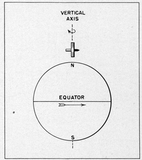
A gyro with its spinning axis set in the East-West position at the equator appears
to turn about its horizontal axis
once each twenty-four hours.
REASON FOR PRECESSION
16. The reason for precession may be explained quite simply if we consider the mass of the rotor to be concentrated in separate particles such as A, B, C, and D in Figure 6a. Figure 6a is a section through the center of the rotor, just as though you sliced it in half with a knife, threw the upper half away and lay the bottom half on the paper. We will assume that the wheel is spinning with considerable velocity in the direction of the arrow R at the top, and we will select that instant in the cycle when the particles are in the positions shown in Figure 6a. If we can show what will happen to four particles equally spaced as are A, B, C, and D, we can show what happens to the entire rotor, since all other particles within it act in the same manner.
17. In order to make the explanation clearer we will simulate the movements of the rotor by corresponding motions of the
booklet itself, and as a first step in this direction we will lay the booklet flat upon the table.
18. Now let us assume that a force F is applied against the rotor just as though we pressed down against the paper with a pencil at this point -- as though we tipped the top of the booklet down, the bottom up. This would tend to rotate the wheel about the axis X-X'. Sir Isaac Newton said, in effect, that all matter is pigheaded and stubborn --that it will continue to move in a straight line unless disturbed, and if disturbed, it will offer resistance to the disturbing force. Let us see what happens to particle A. This particle was moving to the right before we started pushing down at F. Now, however, it tends to
move to the right and down into the paper -- a combination of the motion due to the wheel's rotation and the motion due to our applied force F. Likewise particle C, which was moving to the left, now tends to move to the left and up out of the paper.
19. As a result of these motions the wheel actually turns about the axis YY' which is at right angles to the axis about which the force F was applied. Its motion is the same as though we tipped the right hand side of the booklet down, the left up. This is precession.
20. The reader will probably ask, "What happens to B and D?" Since B and D lie in the axis about which the force F is applied, they are unaffected by that force. Like A and C, however, they are pigheaded and want to have their own way.
21. Because of the wheel's rotation, B moves toward the bottom of the page, D toward the top. But the wheel is now turning about axis YY' because of its precession. Therefore B tends to move toward the bottom of the page and down into the paper, D tends to move
6a
toward the top of the page and up out of the paper. In a perfectly balanced gyro operating without friction, the sum of these motions would exactly offset the force F, so that no motion could take place about axis XX'. Thus the only motion which could result from the application of a force as at F would be precessional rotation about an axis at right angles to the axis about which the force is applied. In other words, the wheel moves in the direction of the least resistance to any force which tends to disturb its plane of rotation -and the point of least resistance is always 90 degrees away in the direction of the wheel's rotation.
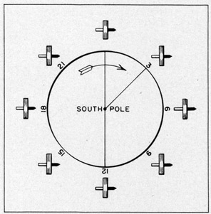
FIGURE 8a
A gyro with its spinning axis set horizontal
at the Pole appears to turn about its
vertical axis once each
twenty-four hours.
OPERATING PRINCIPLES OF THE GYRO-COMPASS
22. In the Gyro-Compass the characteristics of the gyroscope, "inertia" and "precession", which we have just explained, are combined with two constant, natural phenomena -- the earth's rotation and the force of gravity, with the result that the instrument aligns itself with the geographic meridian and provides a constant true north indication regardless of the rolling, pitching, and yawing of the vessel.
APPARENT ROTATION
23. Let us consider the gyro to be mounted at the equator with its axle east and west. We will observe its behavior
from a point in space beyond the South pole as shown in Figure 7a. To avoid confusion we will dispense with the supporting rings in this and subsequent illustrations, and show only the wheel and axle of the gyro, as these are the parts with which we are concerned chiefly.
24. The earth turns in the direction of the arrow, or clockwise, with an angular velocity of one revolution every 24 hours, carrying the gyro around with it; but the gyro, because of its inertia, maintains its original plane of rotation in regard to space just as it did when its base was tilted as shown in Figure 3a. With respect to the earth, however, the gyro rotates about its horizontal axis with an equal velocity (one revolution in 24 hours) but in the opposite direction to the rotation of the earth. After three hours the end of the axle which was pointing east apparently is elevated at an angle of 45 degrees; after six hours, 90 degrees; after twelve hours, 180 degrees; and so on, until, at the end of 24 hours, it is back where it started.
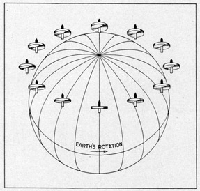
25. Similarly, if we consider the gyro to be placed either at the North or the South pole at the theoretical axis of rotation of the earth, with the axis of the gyro horizontal as shown in Figure 8a, the gyro will appear to rotate, but this time about its vertical rather than its horizontal axis.
7a
FIGURE 9a
A gyro with its spinning axle set horizontal
at any point away from the equator maintains
its plane of rotation in space and apparently
moves about both its horizontal
and vertical axis.
FIGURE 10a
To make the gyro seek the North a mercury
tube is added, its effect being applied
about the horizontal axis.
26. At points between the poles and the equator the gyro appears to turn partly about the horizontal axis and partly about the vertical, because it is affected by both the horizontal component and the vertical component of the earth's rotation. See Figure 9a. The horizontal component of the earth's rotation causes the north end of the axle to rise. The vertical component causes it to turn to the east.
27. The reader will perceive that the difference between gyroscopic inertia and apparent rotation is simply one of
point of view. As far as space is concerned the gyro remains fixed. In comparison with the earth, however, the gyro actually rotates as described above. It is this rotation which makes it possible to apply the force of gravity so as to convert the gyroscope into a North seeking gyro-compass.
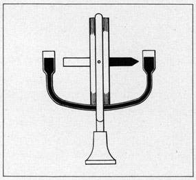
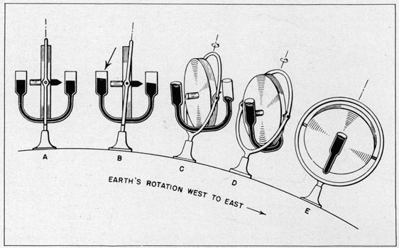
28. The first step in this direction is to cause the gyro to precess toward the meridian. Figure 10 shows diagrammatically a gyro to which has been added a pair of containers with interconnecting tube; the assembly is partially filled with mercury and is attached to the gyro frame in such a way that it will tilt with the gyro when the gyro tilts or rotates about its horizontal axis. With the gyro at the equator and horizontal as shown at A in Figure 11a, the mercury is distributed equally in the tube and its weight exerts an equal downward pressure on each end of the axle. Therefore, in this position, the mercury has no effect upon the gyro. As the end of the axle which is pointing east (the right-hand end) slowly rises, some of the mercury, under the influence of gravity, is transferred to the lower end of the axle, as shown by the arrow at the left in B of Figure 11a. In this position a force is being exerted about the horizontal axis; the effect of the mercury being the same as though we were to push down on the west end (the left-hand end) of the gyro axle. The result is that the gyro precesses about
8a
FIGURE 11a
Effect of the mercury ballistic when applied about the horizontal axis.
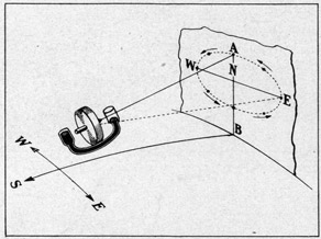
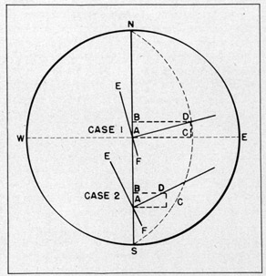
the vertical axis as shown by the small arrows at the top in C and D, the axle turning slowly counterclockwise. As the end of the gyro which at first was pointing east (which we shall now refer to as the north end) precesses toward the meridian, it continues to rise under the influence of the earth's rotation. After the gyro axle has precessed so that it is parallel to the meridian, the excess mercury at the south end causes its precession to continue, and the end of the gyro axle which was at first pointing west (which we shall now refer to as the south end) is carried to the east of the meridian. This south end now commences to rise and the mercury starts flowing back to the north end, precession being gradually diminished until the axle is again horizontal and the mercury evenly distributed. At this point precession of the north end toward the west ceases. The south end continues to rise, however, because it is still east of the meridian, and at length the mercury in the north side of the tube overbalances that in the south side. Precession, therefore, is reversed, and the north end returns toward the meridian, declining more and more as the south end continues to rise. This oscillation of the gyro about the meridian may be clearly understood by referring to Figure 12a which shows the movements of the gyro axle projected onto a vertical plane. The ellipse in Figure 12a is the result of a displacement of the gyro axle of only a few degrees from the meridian. If the gyro axle were pointing east and west at the beginning of the cycle, as shown in Figure 11a, precession would take place through 180 degrees in each direction, and at one extreme the north end of the gyro axle would point east, at the other, west. In any case the gyro never comes to rest, as there is no force tending to restore its axle to a horizontal position until after it has passed the meridian.
29. The ratio of the movement about the horizontal axis (caused by "apparent rotation") to the precessional movement about the vertical axis (caused by the flow of mercury) determines the shape of the ellipse. If the free surface of the mercury in the
9a
FIGURE 12a
Diagram showing the movement of a mercury-controlled gyro wheel when set with its axle pointing east of north.
containers is increased so that more mercury can be transferred, the rate of precession will increase and therefore the ellipse will be flatter. If the mercury effect is decreased, the rate of precession will diminish to a point where the ellipse would, theoretically, be almost circular.
30. In the preceding paragraphs we
have explained the behavior of a gyro under
the simplest form of mercury control, the
mercury being attached directly to the ring,
frame or casing which supports the gyro.
With such an arrangement the mercury can
act only about the horizontal axis, and
therefore the gyro will precess only about
the vertical axis. An additional pressure
is required about the vertical axis in
order to generate precession about the
horizontal axis which will counteract the
natural tendency of the gyro axle to tilt. The manner in which this is accomplished will be shown in the following paragraphs.
31. It will be necessary first, however, to explain the basic elements of an actual gyro-compass. As shown in Figure 13a the rotor is contained in a case (1) and the case is supported on horizontal bearings in a vertical ring (2). The rotor-case
and the vertical ring are free to turn about the vertical suspension axis (3). Although the gyro-compass, as shown in Figure 13a, necessarily differs in its details of construction from the model gyros shown in some of the previous illustrations, it has the same angular freedom about its spinning, horizontal, and vertical axes, and exhibits exactly the same characteristics.
32. Figure 13a shows the addition of an outer frame (4) called the phantom, which is driven by an electrical follow-up system so that it follows every movement of the gyro about the vertical axis. By supporting the mercury tube or ballistic (5) in bearings in the phantom ring we can obtain a controlling action about the vertical axis of the gyro so as to arrest its oscillations and cause it to align itself with the meridian.
FIGURE 13a
Elements of the Gyro-Compass
In order to obtain a more symmetrical construction, the mercury ballistic consists
of two sets of containers and tubes,
instead of the single pair of containers shown in preceding
illustrations.
10a
33. This is accomplished by connecting the mercury ballistic to the gyro case at a point (6) slightly to the east of the vertical centerline. With this arrangement the major effect of the mercury still acts about the horizontal axis and causes the gyro to precess toward the meridian as before; but there is now an additional effect about the vertical axis which causes the gyro to precess about the horizontal axis, introducing a tilt of the gyro counter to the natural tilt resulting from "apparent rotation". Therefore the end of the axle will follow a spiral path as shown in the polar diagram, Figure 14a. The reduction of the oscillation which is produced by the action of the mercury ballistic about the vertical axis is called "Damping". Si careful consideration of the action of the mercury ballistic will make it apparent that the only position of rest which the gyro can find at the equator will be with its axle horizontal and in the meridian. In other words, we have obtained a true, meridian-seeking Gyro-Compass.
FIGURE 14a
Action of the gyro axis when the mercury
ballistic is connected to its casing
through an eccentric pivot.
34. A number of other factors must be considered, however, before we can obtain a gyro-compass which will function accurately and reliably, at various latitudes on a rolling, pitching vessel moving over the earth's surface at considerable speed.
35. We have seen that the action of the mercury ballistic about both the horizontal and vertical axes is made possible by the use of the phantom element. This element serves another important purpose; it provides a means of suspending the gyro so that it is practically free from friction about its vertical axis. The gyro is
supported from the top of the phantom by steel wires and the phantom is kept in
exact alignment with the gyro by means of an electrical follow-up system. The compass
card is a part of the phantom element, the whole of which is supported on ball bearings from the main supporting frame or "spider". Thus, with the exception of the eccentric connection between the mercury ballistic and the gyro case and the upper and lower guide bearings, which are practically frictionless, there is no physical contact which can result in any friction between the sensitive gyro element and the compass card or other external parts.
36. If the compass were to be used on shore, it would be feasible to control the gyro simply by suspending a weight from the phantom, like a pendulum, and connecting the weight to the eccentric pivot on the bottom of the rotor case. This would be impractical on board ship, however, where a compass is subjected to rolling movements in an inter-cardinal plane (northeast to southwest, or northwest to southeast). Inter-cardinal rolling causes a compass to swing in its gimbals, with the result that the pendulum would be subjected to acceleration forces which would cause a continuous torque about the vertical axis of the compass.
11a
37. One way of avoiding this effect would be to stabilize the compass gyroscopically and so prevent it from swinging. In the Sperry compass, however, the complication of stabilizing gyros is avoided by the use of the mercury ballistic, which controls the gyro as we have already explained. The mercury ballistic is non-pendulous: its weight is distributed equally above and below the gyro axle so that it is neither top-heavy nor bottom-heavy. Therefore, no acceleration forces are generated and no torque about the vertical axis of the compass is introduced by the swinging of the compass in its gimbals.
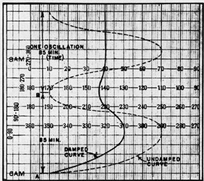
FIGURE 15a
Gyro-Compass damping curve as charted by a course recorder operated from the master compass. A shows settling characteristics when compass is set 30 degrees away from the meridian. B shows undamped oscillations.
Chart is read from bottom up.
38. Under slow rates of inclination such as those produced by the earth's rotation, the action of the mercury ballistic is equivalent to that of an ordinary pendulum, but opposite indirection. Under rapid rates of movement, however, the small bore of the mercury tubes prevents the mercury from surging back and forth and introducing errors in the compass.
DAMPING FACTOR
39. The extent of the damping action is governed by the displacement of the mercury ballistic connecting link from the centerline. Commercial compasses are given a damping factor of 66%, i.e., the eccentricity of the connecting link is such that each swing of the gyro axle from the meridian is one-third of the preceding swing, the amplitude being reduced by 66% at each oscillation. If the compass is
started 30 degrees east of the meridian, the first swing will carry the compass to 10 degrees west, the return swing to 3-1/3 degrees east, then 1-1/9 degrees west, and so on, until it comes to rest. Figure 15a shows graphically the damping characteristics of the gyro-compass.
PERIOD OF OSCILLATION
40. The natural period of the compass, i.e., the time it takes to perform a complete oscillation (from A to B in Figure 14a) is 85 minutes. The period of oscillation is governed by two factors:
(1) The angular momentum of the gyro (the product of weight, speed and square of radius of gyration) and
(2) The torque about the horizontal axis supplied by the action of the mercury ballistic. (This, in turn, is governed by the free surface of the mercury in the containers and the distance of the containers from the horizontal axis.)
12a
41. If the weight or the speed of the gyro is increased, the period of oscillation will be longer. If the free surface of the mercury is increased, the period of oscillation will be shorter.
42. As is explained under the heading Ship's Speed and Course the effect of the ship's speed and course when superimposed on the earth's speed and direction of travel is such as to cause the compass to settle on a new apparent meridian which is not coincident with the true meridian. The compass must have an 85 minute period so that during any given change in speed and course the compass will be oriented to its new apparent meridian during the length of time required to change to the new speed and course.
COMPENSATING WEIGHTS
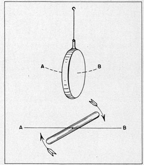
43. Unsymmetrical distribution of weight is another potential source of disturbance, when the compass is swinging, which must be neutralized. When the unsymmetrical weight shown in Figure 16a is swung in the plane A-B, centrifugal stresses act upon it in such a way as to cause all of its particles to place themselves as far as possible from the axis of swing. This causes a tendency to turn, as indicated by the arrows. The same effect may be observed when a watch is swung back and forth on its chain through a small arc. In the gyro-compass this effect is avoided by the use of compensating weights which permit of a symmetrical distribution of weight about the vertical axis.
FIGURE I6a
Effect of unsymmetrical distribution of weight.
44. The foregoing explanation applies particularly to a compass at the equator and in a vessel which is not under way. At points other than the equator and on board ships which are moving over the surface of the earth, certain factors are introduced which would result in errors if they were not compensated or corrected in the design of the compass.
LATITUDE CORRECTION
45. The latitude correction is necessary because of the eccentric connection employed to damp the oscillations of the compass. The correction is made by means of a latitude adjustment scale, no special knowledge of the problem being required in order to make the correction. A complete explanation of the reasons for the latitude error, however, will be welcomed by the student because it involves a general discussion of compass behavior and will give
the student an opportunity to find out
some of the whys and wherefores that might otherwise escape attention.
46. At the equator, where only the horizontal component of the earth's rotation affects the gyro, the axle of the compass is horizontal and parallel to the earth's axis. At the equator, therefore, as soon as the compass has settled on the meridian, the ballistic will he at rest and the compass may be considered as a true gyroscope.
13a
47. If we move the compass to a point to the north or south of the equator, however, it will be affected by the vertical as well as the horizontal component of the earth's rotation. At a point north of the equator, for instance, the north end of the gyro axle
tends to turn toward the east and rise, as the earth rotates out from beneath it. This was illustrated in Figure 9a. It is apparent that the north end of the gyro axle must be precessed continuously in a westerly direction toward the meridian as fast as it is being displaced by the vertical component of the earth's rotation. The force necessary to do this
is obtained automatically by the simultaneous tilt of the mercury ballistic which permits an accumulation of mercury in the lower or south containers so as to precess the axle continuously toward the meridian.
48. If it were not for the offset connection of the mercury ballistic, the gyro axle would eventually settle, theoretically, exactly on the meridian, with the end away from the equator tilted up just enough so that there would be sufficient excess mercury in the containers toward the equator to precess the gyro toward the meridian at the same rate as it is being carried away by the vertical component of the earth's rotation.
49. In order to damp the oscillation, however, the mercury ballistic connection is offset to the east of the centerline of the compass. This produces a counterclockwise
torque about the vertical axis, causing the north end of the axle to precess continuously down. The axle, therefore, settles to the east of the meridian (in north latitudes) at a point where the downward precession of the axle due to torque about the vertical axis is exactly balanced by the horizontal component of the earth's rotation tending to tilt the north end up.
50. As we move the compass further north, the north end of the gyro axle turns to the east faster and rises faster, and for this reason the compass must be precessed faster toward the meridian. The downward pressure on the south end of the axle is correspondingly greater, the torque about the vertical axis is greater, the north- end precesses down faster, and the gyro consequently settles further to the east.
51. South of the equator the effect of the earth's rotation on the gyro is just the opposite: here the south end of the axle tends to rise and turn to the east; the excess mercury is in the north containers, precessing the north end to the east toward the meridian. Torque about the vertical axis is reversed so that the south end is being precessed down at the same rate as the horizontal component of the earth's rotation is tilting it up. Therefore the north end of the axle lies slightly to the west of the meridian.
52. The small angle at which the gyro axle settles from the meridian varies with the latitude, and for this reason a correction must be introduced which will compensate for this natural error at any latitude where the compass may be expected to be used.
53. From zero at the equator, this error increases to 2.9 degrees at 60 degrees north or south latitude; it is easterly in north latitudes and westerly in south latitudes.
54. No attempt is made in the gyro-compass to compel the axle to seek a resting place at variance with its natural settling position. Instead, a latitude adjustment is
provided which moves the lubber-ring the necessary amount to cause the compass indication to be true. Since the transmitter is mounted on the lubber-ring a correctional movement
applied to the lubber-ring also transmits the corrected reading to all repeater compasses.
14a
FIGURE 17a
Diagram illustrating the effect of ship's speed and latitude on the gyro-compass.
This is the "Latitude Correction", and is made independently of the speed and course correction described-below.
SHIP'S SPEED AND COURSE
55. It has been shown that the relatively slow angular movement of the earth's rotation (only one revolution in 24 hours) provides the motive force for the north-seeking precessional movement
of the compass. However, when a vessel
is traveling over the earth's surface, and therefore about the earth's center, the vessel's movement is compounded with that of the earth. If the direction of travel is east or west, the vessel's motion only adds to or subtracts from the earth's motion, and the effect on the indication of the compass is negligible.
56. When the vessel is traveling
north or south, however, the effect is a
maximum because the ship's speed produces
a resultant which is not parallel to the
plane of the earth's rotation. The effect on compass indication is proportional to the ship's speed and course and is explained as follows:
57. In Figure 17a (Case 1)the line AB represents the movement of a vessel steaming due north for a given period of time. Line AC represents the movement of the earth in the same period of time. The actual path taken by the vessel relative to the earth's rotation is AD. AC is the normal plane of rotation. AD is the actual plane of rotation due to combined movement of earth and ship. Therefore, as far as the gyro-compass is concerned, a new
meridian EF is produced which is at right angles to the line AD. At higher latitudes the
movement of the earth is relatively smaller, the new, apparent meridian is displaced farther
from the actual meridian, and a larger correction is required. Thus the amount of the
correction is dependent upon the latitude of the ship (Case 2 of Figure 17a).
58. The displacement of the gyro axle is to the west for northerly courses and to the east 'or southerly courses, and the angular difference between the actual meridian and this new apparent meridian depends upon:
(1) The ship's speed
(2) The ship's course, as it is only the northerly or southerly components of the course which are to be taken into account, and
(3) The latitude, as the higher the latitude the smaller the earth's surface speed and therefore the greater the effect of the ship's speed.
15a
59. The compass is provided with a corrector mechanism which automatically applies the correction due to course and speed at any given latitude by moving the lubber line the required amount to compensate for this error. The compass indicates the ship's true heading on all courses, and no corrections have to be applied by reference to tables.
NOTE: THIS BOOK APPLIES TO PANELS BEARING SERIAL NOS. 1207 THROUGH 1281, 1402 THROUGH 15C1, .1902 THROUGH 2001, 2302 THROUGH 2401, 3322 THROUGH 4346, ALSO 4347 THROUGH 4846, ALSO 4847 THROUGH 5463 AND 5544 THROUGH 5806,
SPERRY GYROSCOPE COMPANY, INC. MANHATTAN BRIDGE PLAZA, BROOKLYN, NEW YORK
1
INTRODUCTION
1. The Gyro-Compass uses both direct and alternating current. The direct current, which is supplied to the compass at 70 volts, is known as the service supply and is used to operate the motor end of a motor-generator set, the compass repeater and part of the amplifier circuit. This current is obtained from the ship's supply and is reduced to 70 volts as described in this text.
2. The alternating current is used to operate the compass rotor. It is supplied at 50 volts, 3 phase and 210 cycles by the generator end of the motor-generator set.
3. This book treats of (I) the control panel which is used to control these D-C and A-C supplies, (II) the regulator or resistor for reducing the ship's supply voltage, and (III) the alarm unit which is used to warn the ship's personnel of an interruption of the ship's supply.
1. The Control Panel provides electrical control for the Master Gyro-Compass, the motor-generator and the repeater compasses, and indicates through a D-C voltmeter the regulated voltage to the Gyro-Compass Equipment.
2. In the following paragraphs the units which appear on the panel front, and inside the panel box, are described in this order.
PANEL FRONT
3. The following units appear on the front of the panel. See Fig. 1.
a) Voltmeter (range 0-100), for indicating the D-C voltage supplies to the repeaters, the alarm unit, and the motor end of the motor-generator.
b) Circuit breaker, for connecting the ship's D-C supply to the units just mentioned. The circuit breaker plunger is pulled out to connect the ship's supply.
c) Push-button, located in the upper right corner of the panel, used to shut down the equipment. Its function is to disconnect the circuit breaker
coil, thereby releasing the contacts and disconnecting the ship's supply.
d) Repeater snitch, located below the voltmeter in the middle of the panel, used for connecting the repeater compasses to the transmitter on the Master Compass.
e) Fuses, plug type. There are 3 fuses, 2 in the ship's supply circuit and
1 in the repeater switch circuit.
PANEL BOX
4. In addition to the items mentioned above, which, of course, protrude through the rear of the panel, the following items are located inside the panel box:
a) Motor field resistor, located in the middle of the box, connected in series with the motor field. It is used to control the compass rotor speed,
by varying the speed of the alternator. Shorting out steps of the resistor with a jumper DECREASES the compass speed. The normal speed of the
motor-generator is 2100 r.p.m.
b) Alternator field resistor, mounted on the same frame with the motor field resistor, connected in series with the alternator field for controlling the A-C voltage to the compass rotor.
VOLTAGE REDUCTION DEVICE
5. The ship's D-C supply is stepped down from normal of about 115 volts to 70 volts for the D-C service supply. This supply, however, must be constant within ±5 volts in order to obtain satisfactory operation of the compass. Therefore, 3 devices for obtaining a proper service supply are available, the device selected depending on the voltage
3
FIGURE 1
CONTROL PANEL
FIGURE 2
CONTROL PANEL, VIEW INSIDE BOX
4
and regulation of the ship's supply. The devices are:
a) Series resistor, used when the ship's supply is regulated to 115 volts or is constant (within -15 volts) at any voltage between 100 and 125 volts. The resistor, Sperry part #116733, has a total resistance of 7.4 ohms and is provided with taps for adjusting the service voltage to 70 volts. If the resistor is used, it should be connected between terminals R9 and RO on the control panel terminal block.
b) Carbon pile regulator, used to provide a 70 volt output when the ship's supply voltage varies between 90 and 130 volts. If the regulator is used, its terminals 1, 2 and 3 should be connected to terminals CP1, CP2, and CP3-4 respectively on the control panel terminal block. Also a jumper
must be connected between terminals 3 and 4 on the regulator. The regulator, described below, is the voltage reduction device most frequently used.
c) Carbon pile regulator and a resistor - If the ship's supply varies between 90 and 150 volts, it will be necessary to connect a 2 ohm resistor (Sperry part #129367) in series with the carbon pile. This may be done by removing the jumper between terminals 3 and 4 on the regulator and connecting the 2 ohm resistor between these terminals.
6. The voltage reduction device should be mounted near the control panel and connected to it by passing the cable through an entrance hole in the panel box.
CARBON PILE REGULATOR
7. The regulator comprises a voltage coil which operates an arm to vary the pressure on two piles of carbon discs. The resistance of these discs to a flow of electricity varies inversely as the pressure on them, hence the pressure arm is arranged so that a spring exerts the pressure and the voltage coil acts against the spring to lessen the pressure. The coil is connected across the regulated supply and the carbon piles are
connected in series with the line, as shown in Fig. 3. One cycle of operation of the regulator would be as follows: (1) the D-C supply voltage increases, thereby raising the voltage across the coil, (2) the coil attracts the pressure arm against its spring, lessening the pressure on the carbon piles, (3) the resistance of the carbon piles increases, and (4) this increases the resistance in the supply line and the load voltage drops.
FIGURE 3
CARBON PILE WIRING DIAGRAM
8. A dashpot damper is connected to the pressure arm to prevent any tendency to hunt when the changes of voltage are rapid. A resistance is connected in series with the coil to reduce the coil voltage to a safe heating value and also to limit the flux density in the magnetic circuit as required for good voltage regulation.
5
ALARM UNIT
9. Since the compass equipment is dependent on the ship's supply and its accuracy may be seriously affected by a failure or an interruption of the current, it is essential that adequate warning be given in case the supply does fail, so that steps may be taken to remedy the difficulty at once. For this reason an alarm unit, arranged to sound an
alarm in the wheelhouse in case the 70 volt D-C supply is interrupted, is supplied with the equipment.
10. The alarm unit (Fig. 4) comprises a weatherproof case containing a voltage relay, a buzzer, a set of dry cells which supply current for operating the buzzer, and a toggle switch mounted on the front of the case. The relay is connected across the 70 volt
repeater supply, preferably at the bridge. When the compass supply is normal, the relay
armature is held in place by the energized magnet coil. The circuit to the buzzer is controlled by the toggle switch which ordinarily is turned so as to silence the alarm.
11. Failure or reduction of the compass supply voltage causes the relay armature to drop, closing the buzzer circuit and sounding the alarm until the switch is turned OFF to silence it. To prevent the switch from being left in the OFF position when the supply has been restored and the relay armature returned to its normal operating position, the circuit is so arranged that the buzzer is again sounded when the armature is in the normal position. The switch is then turned ON which silences the buzzer during normal operation.
6
FIGURE 4
ALARM UNIT, COVER TURNED OVER
7
SECTION II
- OPERATION -
TO START GYRO-COMPASS
12. Set Master Compass and repeater compasses approximately to true heading of ship. NOTE: Turn Master Compass by grasping both the vertical and phantom rings.
13. Pull out circuit breaker plunger to start motor-generator and compass. Hold
plunger out by hand until motor-generator speeds up (in about 5 seconds). If necessary,
rock Compass rotor case, in plane of rotor, until it starts.
14. When starting alongside a dock, wait until rotor is up to speed (in approximately 10 minutes), then turn on follow-up switch on amplifier panel. (When starting up
at sea, release the rotor case and vertical ring locking latches immediately and steady the rotor case by hand until rotor is up to speed.)
15. Wait one minute for rectifier tube filaments to heat up.
16. Release rotor case and vertical ring locking latches.
17. Turn ON azimuth motor switch at amplifier panel.
18. Turn ON all repeater switches.
19. Turn switch at alarm unit so as to silence alarm.
20. Reset Compass on ship's heading by pressing down on one or the other of the rotor case bearing housings, and if necessary, level the rotor by pressing against the vertical ring. Check repeaters, and synchronize if necessary.
IF ALARM SOUNDS DURING NORMAL COMPASS OPERATION
21. A momentary failure of the supply current will cause buzzer to sound until the supply is restored, and in such case the accuracy of the compass will not be affected. It is well, however, to check repeaters with Master Compass after any momentary failure of the supply.
22. If alarm continues to sound, the current failure evidently is more than temporary. Turn switch OFF to silence buzzer. Examine control panel immediately. The circuit breaker is adjusted to open approximately 5 seconds after ship's supply fails. If, on examination, the circuit breaker is found open, repeat instructions for starting compass at sea. Check Master Compass and repeaters.
23. If motor-generator fails to start when circuit breaker is closed, steps should be taken immediately to locate cause of trouble. Lock Master Compass rotor case upright, with locking device if necessary, and when the trouble has been located and remedied, start Master Compass according to directions for starting compass at sea.
8
TO STOP COMPASS
24. Turn OFF repeater switches.
25. Turn alarm switch to silence buzzer.
26. Turn OFF azimuth motor switch.
27. Turn OFF follow-up switch.
28. Depress push button on control panel until circuit breaker snaps open, whence the voltmeter will go down to O.
29. If stopping compass at sea, steady rotor by hand until it stops, then lock it with locking latches. If stopping at dock, there is no need of supporting rotor by hand;
it may be locked immediately.
30. Inspect equipment and clean same, if convenient. The equipment can best be
cleaned while it is still warm.
9
SECTION III
- MAINTENANCE -
31. Keep panel clean and free from oil and grease.
32. Keep circuit breaker contacts clean and bright.
33. Test alarm unit every week by turning alarm switch OFF while compass is operating. If alarm does not sound, check alarm battery. Average life of these dry-cells is
3 to 4 months.
34. Keep 20-ampere fuses in ship's supply fuse sockets.
35. Keep proper size fuse in repeater circuit fuse socket.
36. CARBON PILE ADJUSTMENTS.- The carbon pile regulator (used in some installations to keep the 70 volt D-C supply constant) is a simple and rugged piece of apparatus and is carefully tested and adjusted before shipment. Adjustment of the voltage setting,
as described in the following, may occasionally be necessary, but otherwise very little attention should be required.
37. If regulator does not function properly, carefully check all connections to be sure they are complete and tight. If voltage remains too high, probably the regulator
coil circuit is open. This can be checked by holding a wrench or apiece of iron close to the magnet. If there is no strong pull, the circuit is open or partly so.
38. The following adjustments should not be attempted until all other possible causes of trouble have been eliminated.
39. VOLTAGE ADJUSTMENT - The voltage which the regulator will hold can be changed ONLY by changing the position of the 1/4" nuts on stud to which spring is attached, and which protrude through bracket at left side of regulator. One of these nuts is used merely
as a locknut. To raise voltage, the nuts should be screwed farther up on stud, while to
reduce voltage they should be screwed farther out. When setting voltage which regulator
is to hold, be sure regulator has reached its normal operating temperature and that supply voltage is approximately normal. When coil is cold, it tends to regulate to a value lower than normal.
40. CARBON PRESSURE ADJUSTMENT - If the regulated voltage changes with heavy loads and the fault is not in the connections or the generator, or due to sub-normal operating temperature, the difficulty may be due to lack of pressure on carbons. This can be
corrected by means of large knurled nut at left side of carbon pile. To adjust pressure on carbons, have no current on magnet, pull down on armature and screw up on knurled nut until spring arm will just barely go back against its stop when armature is released. Then loosen adjusting nut 1/2 turn which will allow arm to go back freely against its stop. NEVER try to change voltage setting by adjusting this knurled nut, as this will only result in reducing range of regulator.
41. DASHPOT ADJUSTMENT - The dashpot is of the inverted air type, with a graphite
10
plunger and an air vent adjustment. This vent should be adjusted so as to overcome any
tendency to hunt when load is light, or during starting. Care should be taken not to
close up vent too much as this will reduce regulator sensitivity. The dashpot is constant in action regardless of temperature changes and its construction is such that it will not become clogged with dust.
42. REPLACEMENT OF CARBONS - Broken or damaged carbons may be readily replaced by removing one of the porcelain guide rods of the stacks. Care should be taken not to add or omit any carbon plates.
11
FIGURE 5
SCHEMATIC WIRING DIAGRAM: GYRO-COMPASS EQUIPMENT
NOTE UNITS AND CONNECTIONS NOT BOXED IN ARE ON CONTROL PANEL
12
FIGURE 6
GYRO-COMPASS MK XIV, MOD. I
WIRING DIAGRAM #75454
13
SECTION IV
COMPASS CONTROL PANEL ASS'D. #642639-L
Panel front panel.
Symbol No.
Part Number
No. Req'd.
Description
1
144850
1
Fuse, 5 Amp.
2
163337
2
Fuse, 20 Amp.
3
144854
1
Switch, 5 P.S.T. Rotary
4
74949
1
Switch Ass'd., Clapper
5
144879
1
Knob Ass'd., Clapper Switch
6
154886
1
Voltmeter (0-100 V. D-C.
7
150268
1
Button, Push
ALARM UNIT ASS'D. #642640-D
Part Number
No. Req'd.
Description
75666
1
Gasket, Front Cover
154681
1
Switch, Toggle
200653
1
Buzzer Ass'd.
114471
1
Spring, Buzzer
200654
3
Battery, Dry Cell (1-1/2 Volt
1056
1
Coil Ass'd-, Relay
123960
1
Armature Ass'd., Relay
127885
2
Spring, Relay Armature
123957
2
Screw Ass'd., Relay Contact
4675
1
Unit Ass'd., Resistance (A-350)
CARBON PILE REGULATOR ASS'D. #75023-E
Part Number
No. Req'd.
Description
149579
1
Unit Ass'd., Resis. (36 ohms)
149578
101
Disc, Carbon (1/16" thick)
140949
1
Coil, Regulating (17 ohms)
RIBOHM RESISTOR ASS'D. #116733-F
Part Number
No. Req'd.
Description
103345
2
Unit Ass'd., Resis.(D-0.9)
RESISTOR ASS'D. #129367-B
Part Number
No. Req'd.
Description
86038
4
Unit Ass'd., Resis. (.5 ohm)
INSTRUCTIONS NO.17-AP-642202-D
NOVEMBER 1943
NOTE: THIS BOOK APPLIES TO PANELS BEARING
SERIAL NOs. 5472 THROUGH 6010.
SPERRY GYROSCOPE COMPANY, INC., MANHATTAN BRIDGE PLAZA, BROOKLYN, NEW YORK
1
INTRODUCTION
1. As explained in the compass instruction book, the phantom element of the compass is kept in alignment with the sensitive element of the compass by means of a follow-up system. The Mk. XIV, Mod. 1 Compass employs a thermionic type of follow-up system which is controlled by a separate electrical panel called the Amplifier Panel. This book describes the follow-up system and gives instructions for operating the amplifier panel.
2. The thermionic type of follow-up system has several advantages over other types of follow-up systems in that:
(a) It permits smooth and accurate transmission of the Master Compass readings to the repeater compasses.
(b) It eliminates any rolling or sliding contact between the sensitive and phantom elements. This reduces friction about the vertical axis of the sensitive element, thus improving the accuracy of the compass.
(c) Since there are no rolling or sliding contacts, maintenance requirements are minimized.
3. The follow-up system treated in this book is of the "non-hunting" type.
2
AMPLIFIER PANEL
SECTION I
DESCRIPTION
1. The function of the amplifier panel is to control automatically a source of electrical supply to the azimuth motor on the compass so that this motor will run in the proper direction and for the proper length of time to keep the phantom element in alignment
with the sensitive element. The signal, which causes the motor to operate is given by a
follow-up transformer mounted on the phantom element. The transformer has a primary coil
and two secondary coils, the coils being mounted on an E-shaped core so that the primary coil is in the center and the secondary coils are on either side of it. An armature carried by the sensitive element completes the magnetic circuit by bridging the gap between the primary coil and the two secondary coils in the following manner:
2. When the phantom and sensitive elements are aligned, the follow-up transformer armature passes equal amounts of magnetic flux through each secondary coil. These fluxes
are opposing each other, hence, no signal is generated and the azimuth motor does not operate. When the armature is displaced from this balanced position by a movement of the phantom element away from the sensitive element, unequal fluxes pass through the transformer secondaries, and the difference of the unequal voltages thus induced is transmitted to the grid of the amplifier tube on the amplifier panel. The amplifier tube intensifies the signal, which then serves to control two grid-controlled, gas-filled rectifier tubes. The output of these tubes is fed through the armature of the shunt field azimuth motor, which then drives the phantom element in azimuth to restore its alignment with the sensitive element.
3. The primary coil of the follow-up transformer on the phantom element of the compass is supplied with 210 cycle a-c from phase #9-10 of the gyro supply through a current limiting resistance R1 mounted near the top of the phantom ring. The secondary coils are
tuned for maximum output at 210 cycles by .20 m.f. condensers Cl and C2 mounted on small brackets near the top of the phantom ring. The secondary coils are connected in series opposing, so that when their voltages are equal, their combined output is zero.
4. The amplifier may be divided into two parts for purposes of explanation: (1) the voltage amplifier, consisting of vacuum tube V1 and its associated components, and (2) the power amplifier, consisting of the rectifier tubes V2 and V3 and the azimuth motor circuit. The voltage amplifier merely serves to amplify the signal from the pick-up transformer to a value suitable for operating the power amplifier, which in turn supplies and controls current to drive the azimuth motor.
ELECTRICAL CIRCUITS
5. As shown in figure 2, the compass signal (shown in red) is carried from terminals A and B of the follow-up transformer, through the compass cable, to the amplifier panel where it is fed to the grid and cathode of the type 2A5 vacuum tube Vl. This tube operates as a linear amplifier and, therefore, delivers to the primary, 5-6, of transformer Tl an amplified reproduction of the compass signal. This is an alternating voltage built up across 5 and 6 as the signal on the grid of V1 permits more or less current to flow in the plate circuit.
3
6. The plate supply of tube Vl (shown in blue) is obtained from terminal T4 which is positive d-c from the ship's supply. From this terminal the supply passes to K, the
screen grid terminal of tube V1, and also through the primary of transformer T1 to the plate of Vl, through Vl to its cathode, through potentiometer P1 to terminal T5 which is the negative side of the ship's supply.
7. The plate current drawn by V1 (approximately 10 milliamperes) must pass through P1. A voltage drop is thus obtained and communicated to the grid of V1 through the resistance R2 and the signal circuit, the amount of drop depending upon the position of the sliding contact of P1. The voltage drop serves to bias the grid of tube V1 to the proper operating point, and negative with respect to the cathode. Resistance R2 and condenser C3 serve to
filter out any ripple which maybe present in the drop across the potentiometer P1. Condenser C4 permits amplified signal currents in the primary of transformer Ti to return to the cathode of V1 without passing through the plate supply circuit. As the currents are the result of an induced EMF in the follow-up transformer, they are, therefore, alternating in character and can be passed through the condenser.
8. The filament or heater circuit of tube V1 (shown in black) is obtained from the secondary coil AS-AF of the power transformer T2.
9. The power stage employs two grid-controlled, gas-filled, rectifier tubes V2 and V3. These tubes are half-wave rectifiers and consequently pass current on positive plate alternations only, and then only when the grids are sufficiently positive to permit tube operation. By supplying the grids with a bias voltage of the same frequency as the plate supply, the firing of each rectifier can be controlled by controlling the potential on its respective grid. The potential of each rectifier grid is controlled by the signal from the coupling transformer Ti superimposed on the bias voltage.
10. The plate circuit of tube V2 (shown in blue) starts at tap 276 of the power supply transformer T2, passes to the plate of V2, through V2 to its filament, from the filament through the heater winding in the power transformer for V2, through the a-c ammeter M to one side of the azimuth motor armature AZ2, through the armature to one side of the azimuth motor switch S, through the switch to the azimuth motor series resistance R3, and through the resistance to terminal TS of the secondary of the power supply transformer T2.
11. The plate circuit of tube V3 (also shown in blue)starts at terminal TS of the secondary of the power supply transformer T2 and passes to one end of the series resistance R3, through the resistance to one side of the azimuth motor switch S, through the switch to one side of the azimuth motor armature AZ1, through the armature to the a-c ammeter, through the ammeter to the plate of tube V3, through tube V3 to its filament and from the filament through the heater winding for V3 to tap 276 of the secondary of the power supply transformer T2.
12. The filament or heater circuits for tubes V2 and V3 (shown in black) are obtained from the two secondary coils MS-MF of the power transformer T2. The same conductors are used for the grid returns.
13. The grid circuit of tube V2 (shown in red)starts at terminal 8 of the coupling transformer T1, passes through the grid resistor R4 to the grid of tube V2, through the tube to the filament, from the filament through the filament heater winding for V2 to terminal
4
0C of the 10-volt winding 0S-0C-0F on the power transformer T2. The winding 0S-0C-0F, together with the small microfarad condenser C5 and the resistor R7, forma phase-shift bridge. The common terminal of the condenser and the resistor is connected to terminal 7 on T1. The phase-shift bridge is so connected that a bias of 5 volts is always applied to the grid of V2.
14. The grid circuit of tube V3 (also shown in red) starts at terminal 4 of the coupling transformer T1, passes through the grid resistor R5 to the grid of tube V3, through the tube to the filament, from the filament through the filament heater winding for V3 to terminal NC of the 10-volt winding NS-NC-NF on the power transformer T2. The winding NS-
NC-NF, together with the small microfarad condenser C6 and the resistor R8, form a phase-shift bridge. The common terminal of the condenser and the resistor is connected to terminal 3 on T1. The phase-shift bridge is so connected that a bias of 5 volts is always applied to the grid of V3.
15. The two secondaries of the coupling transformer T1 are so connected to the grids of the rectifier tubes V2 and V3 that when a signal is received from the compass follow-up transformer and amplified through the amplifier tube V1, the signal voltage on the grid of
V2 is in phase with the signal voltage on the grid of V3. This signal voltage is superimposed on the bias voltage of each rectifier tube, hence the voltage applied to the grid of each tube is the resultant of the signal and bias voltages.
16. The azimuth motor field (shown in blue) is connected as a shunt field through a series resistance R6 of approximately 170 ohms on the amplifier panel to the ship's 115-volt d-c supply. One side of this field circuit is connected directly to the positive side of the ship's d-c supply. The other side returns to compass #10 terminal which is negative and common to both the ship's supply and the 210 cycle a-c compass rotor circuit.
17. The signal for tube V3 originates when the transformer armature on the compass moves upward, as viewed in figure 2. The signal for tube V2 originates when the transformer armature moves downward, as viewed in figure 2.
OPERATING CHARACTERISTICS
18. The amplifier is wired to provide non-hunting operation of the follow-up system, that is, the azimuth motor comes to rest without oscillation as the follow-up transformer is centered.
19. Under normal operation and with the follow-up transformer centered, the rectifier tubes glow steadily and the current measured by the ammeter in the plate circuit will read about 0.4 ampere. The bias voltage on the grid of each rectifier tube causes the tube to pass current continuously. This is accomplished by having the bias voltage nearly in
phase with the plate voltage, so that when the plate is positive the bias voltage will cause the tube to fire.
20. As the follow-up transformer on the compass is displaced to one side with respect to the armature, the amplified signal voltage from transformer T1 is added to the bias voltage on each rectifier tube, the output of one rectifier tube is decreased while the output of the other is increased. As shown in figure 2 the output currents from tubes V2 and
V3 pass through the azimuth motor armature in opposite directions. The difference between
5
the two currents provides the torque to turn the azimuth motor in a direction to bring the follow-up transformer back into alignment with the armature and reduce the signal voltage to zero. Hence, a displacement of the follow-up transformer to one side causes the azimuth motor to turn in one direction while a displacement of the follow-up transformer to the other side causes the azimuth motor to turn in the opposite direction.
SECTION II
INSTALLATION
21. When installing the amplifier, it is necessary simply to connect the terminals on the amplifier panel terminal block to the corresponding terminals in the compass and on the compass control panel. It is important that terminals T4 and T5 on the amplifier panel are connected to the ship's supply of 115-volts, d-c. The polarity of these terminals must also be correct; that is, T4 must be positive and T5 negative.
22. After making all connections correctly, start the compass rotor and let it come up to full speed. Close the "Follow-Up" switch on the amplifier panel; then wait approximately one minute for the rectifier tube filaments to heat up. In starting up the first
time, have someone hold the azimuth motor armature on the compass, then close the "Azimuth Motor" switch on the amplifier panel. The amplifier should start to function immediately
and the azimuth motor should turn the phantom element into exact alignment with the sensitive element. If the azimuth motor turnstile phantom out of alignment with the sensitive element, it will be necessary to reverse the azimuth motor brush leads between the brush holders and the azimuth motor terminal block so that the motor will run in the right direction to restore the alignment of the phantom and sensitive elements.
SECTION III
OPERATION
STARTING
23. To start the compass proceed as follows:
24. Follow the starting instructions given in the compass instruction book and control panel instruction book which are supplied with the equipment.
25. When the compass rotor has come up to speed, close the "Follow-Up" switch. Then wait for one minute for the rectifier tube filaments to heat up.
6
26. Close the "Azimuth Motor" switch, first making sure the rotor case and vertical ring locking latches have been released.
STOPPING
27. Open the "Azimuth Motor" switch.
28. Open the "Follow-Up" switch.
29. Shut down the compass as explained in the compass and control panel books.
SECTION IV
MAINTENANCE
ADJUSTMENTS
30. The current through the azimuth motor armature from the amplifier is indicated on the a-c ammeter on the amplifier panel and should be approximately 0.4 ampere. At semiannual intervals it may be necessary to adjust the sliding contact on the potentiometer P1 by means of a small screwdriver in order to obtain the best possible operation. This adjustment should be made only by a service engineer.
31. As the rectifier tubes age or after they have been used several thousand hours, it will be found that the azimuth motor current has decreased and may be considerably less than 0.4 ampere. This current can be restored to normal by shorting out some of the azimuth motor armature series resistance R3 on the back of the amplifier panel.
TUBES, MOTOR, ETC.
32. The life of the C1A rectifier tubes varies. The tubes may function satisfactorily for a few hundred hours or for several thousand hours. As a C1A rectifier tube ages, the starting voltage of the tube gradually increases and it will eventually become so high that the supply voltage from the power transformer will not be enough to fire the tube, in which case the tube is no longer of any use. If one tube in the amplifier fails, it is
probable that the starting voltage was too high or the filament burned out. A new rectifier tube then should be put in its place. If the other tube is very old, it would be advisable to replace both rectifiers in order to have the amplifier function smoothly.
33. It is improbable that the type 2A5 vacuum tube will fail except after a very long time. This tube is one of the indirectly heated cathode type, is very rugged, and is being operated in the amplifier at less than half its rated load.
34. If both rectifiers go out suddenly, look for an open in the azimuth motor armature circuit or an open resistance unit, R3, in series with the azimuth motor armature.
7
35. If by holding the follow-up transformer armature approximately in the center and then by moving it first to one side and then the other, the signal controls the rectifier tubes, and still the azimuth motor has no torque at all, it is very probable that the field circuit to the azimuth motor is open. There may be an open field connection or the resistance R6, in series with the motor field and located on the back of the amplifier panel, may be burned out.
36. IMPORTANT NOTE. When the non-hunting type of follow-up, described in this booklet, is used with the Mark XIV, Mod. 1 Gyro-Compass, the lost motion device on the compass transmitter must be set for zero lost motion.
8
FIGURE I
AMPLIFIER PANEL-FRONT AND REAR VIEWS
FOR RATINGS AND DESIGNATIONS 0F ITEMS SHOWN IN THIS FIGURE SEE PAGE 9.
9
ELECTRICAL RATINGS OF ITEMS SH0WN IS FIG. 2
Item
Name
Rating
Part No.
C1, C2
*Follow-Up Transformer Secondary Coil Condenser
.20 MF
154848
C3
Filament Bias Filter Condenser
2 MF
151442
C4
By-Pass Condenser
2 MF
151442
C5, C6
Phase-Shift Bridge Condenser
.75 MF
150648
R1
*Follow-Up Transformer Primary Coil Series Resistance
1200 ohms
133324
R2
2A5 Amplifier Tube Bias Filter Resistor
.05 Meg.
147371
R3
Azimuth Motor Armature Series Resistors
( 25 ohms
(151033
(146 ohms
(110093
R4, R5
Grid Resistor
.01 Meg.
151040
R6
Azimuth Motor Field Series Resistors
( 25 ohms
(151033
(146 ohms
(110093
R7
Phase-Shift Bridge Resistors (2)
5000 ohms ea.
158132
R8
Phase-Shift Bridge Resistors (2)
5000 ohms ea.
158132
T1
Rectifier Input Transformer
Type 1651
150974
T2
Power Transformer
642645
P1
2A5 Amplifier Tube Bias Filter Potentiometer
1000 ohms
154695
V1
Amplifier Tube (Vacuum)
2A5
144132
V2, V3
Rectifier Tubes (Thyratron)
C1A
140406
*Follow-Up Transformer
-
152076
*Follow-Up Transformer Primary Coil
-
152077
*Follow-Up Transformer Secondary Coil
-
152078
M
A-C Ammeter (Range 0-1 Amp.)
-
151029
*Azimuth Motor Assembly
-
642135
*Azimuth Motor Armature
-
91296
*Azimuth Motor Field Coil
-
91297
Items marked (*) belong to the Gyro-Compass Assembly.
FIGURE 2
AMPLIFIER-SCHEMATIC WIRING DIAGRAM
10
AMPLIFIER PANEL #642202 -AL
Symbol No.
Part Number
No. Req'd.
Description
1
642645
1
Transformer Ass'y., Power
2
150974
1
Transformer Ass'y., Rectifier Input
3
151029
1
Ammeter (0-1 Amp. A.C.
4
650029
2
Thyratron (CIA
5
144132
1
Tube, Vacuum (2A5
6
154695
1
Potentiometer Ass'y.
7
151442
2
Condenser (2MFD
8
147371
1
Resistor (.05 Megohm
9
151040
2
Resistor (.01 Megohm
10
151033
2
Resistor (A25-T1
11
110093
2
Resistor (B146-T1
12
146405
3
Clamp Ass'y., Tube
13
144954
2
Socket Ass'y. (4 Prong
14
143435
1
Socket Ass'y. (6 Prong
15
151031
2
Switch Ass'y., 2 P.S.T. Toggle
16
158132
4
Resistor (5000 0hms
17
150648
2
Condenser (0.75 MFD
INSTRUCTIONS NO. 17-MG-67633-B
AUGUST 1940
SPERRY GYROSCOPE COMPANY, INC. MANHATTAN BRIDGE PLAZA, BROOKLYN, NEW YORK
2
FOREWORD
1. The Motor-Generator is designed for conversion of the ship's supply of 115-volt D-C to 50 volt, 3-phase, 210 cycle A-C for driving the gyro-wheel of the Master Gyro-Compass.
2. The 115-volt ship's supply is reduced through a carbon pile regulator or a series resistor to 70 volts for driving the motor end of the Motor-Generator, and also the repeater system of the Master Compass.
DESCRIPTION
3. The alternator end of the machine consists of an inductor type generator, the
stationary windings of which are a D-C field and a 3-phase A-C winding. The 5 terminals
are brought out to a common terminal block on the side of the machine. The alternator
field winding, and also the motor field winding, are excited from the Control Panel through adjustable resistors.
WIRING DIAGRAM
MOTOR-GENERATOR MK. XXXVI, MOD. 1
4. The motor end consists of an interpole compound-wound motor. The speed of the motor is controlled by resistors located on the back of the Control Panel. At the time the Compass is installed, these resistors are adjusted to give a Motor-Generator speed of 2100 r.p.m. under normal running conditions. Once made,
this adjustment becomes permanent unless the normal value of the ship's supply is altered.
5. The armature shaft is mounted on ball bearings enclosed in housings in the end brackets. The bearings are the deep groove type, with their inner races clamped to the shaft. The bearing at the generator end is locked in position and acts as both a radial and a thrust bearing. The bearing at the motor end floats to allow sufficient freedom for expansion. The motor end of the shaft is provided with an oil-thrower to prevent creepage of oil or grease from the bearings to the electrical connections of the armature.
6. The machine is suspended on 4 shock-mounts. See outline drawing on page 4.
OPERATION
7. The machine is operated from the Control Panel, by means of the circuit breaker. For starting, the circuit breaker plunger is pulled out and held by hand until the Motor-Generator speeds up, when the voltage across the breaker coil will be sufficient to hold the plunger and the operator's hand may be released. Usually the plunger
must be held for about 5 seconds.
8. The machine is stopped simply by pressing the push button on the Control Panel. The button disconnects the circuit breaker coil, thereby allowing the breaker to open.
3
MAINTENANCE
9. Inspect the commutator and brushes every week. If the brushes slide freely
in the holders, they will bear upon the commutator with the proper tension. Brushes which have worn down more than 3/8-inch should be replaced.
10. Sparking, the chief cause of commutator troubles, may be entirely prevented by:
a. Properly sanding in new brushes, when substituting for old ones, until the bearing surface of the brushes conforms perfectly to the curved surface of the commutator.
b. Never allowing oil or carbon dust to collect in the vicinity of the brush holders.
c. Keeping the ship's supply voltage within 10 volts of the normal value.
d. Keeping the commutator surface free from oil, grease and moisture.
e. Keeping the slots between the commutator bars free from dust and grease.
11. A dirty commutator should be cleaned with a piece of soft cloth moistened
with carbon tetrachloride. Remove all traces of carbon, and polish the commutator preferably with a fresh piece of cloth moistened with alcohol. This will remove any excess
carbon tetrachloride and insure proper drying of the insulation. If need be, clean the
brush holders in the same manner, after removing the brushes, making sure that the brushes are replaced properly and slide freely in the holders.
12. A rough commutator should be carefully smoothed with a piece of fine sandpaper while the machine is running. Make sure to remove all copper and carbon dust from the vicinity of the brush-holders after this operation. If necessary, clean out the slots between the commutator bars with a sharp piece of hard wood. DO NOT USE EMERY ON COMMUTATOR.
13. The neutral or normal operating position of the brush-holders is set at the factory and is clearly marked by a white line across the brush-holder support and the
brush ring. If the machine is disassembled, care should be taken not to shift the brush-
holders from their normal marked position. However, should the brush-holders be moved
from their proper position, the brush ring to which the brush-holders are attached should be shifted back to its marked position by loosening the brush ring clamp screw, moving the ring in the required direction and tightening the screw.
LUBRICATION
14. The ball bearings of the motor-generator are packed with grease and require only an occasional additional application of lubricant through the cups provided at each end of the machine. Keep the cups filled with a good grade of bearing grease (such as is supplied in the spare part box).
15. The cups should be filled before starting the equipment, and the handles turned down slightly. It will be necessary to give them only about 1 turn every month thereafter.

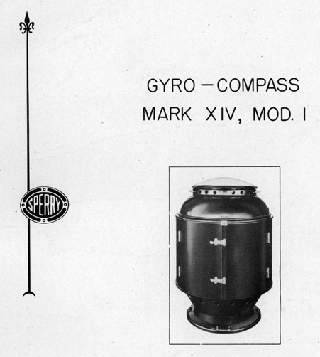
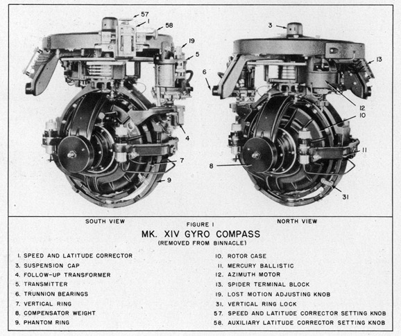
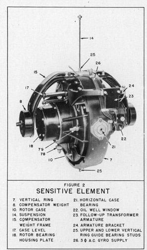
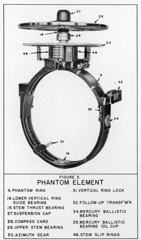 9. It has already been said that the suspension supports the sensitive element. The top of the suspension is secured to the top of the phantom element (refer to figure 3). As the sensitive element is turned in azimuth (i.e., about the vertical axis) it would tend to twist the suspension. However, the phantom element is also arranged so that it can turn about the vertical axis and, by means of the follow-up system, is made to follow every movement of the sensitive element. This system of support supplies a practically frictionless mounting of the sensitive element. The manner in which the phantom is made to follow the sensitive element is described under FOLLOW-UP SYSTEM.
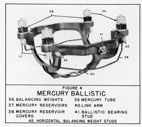
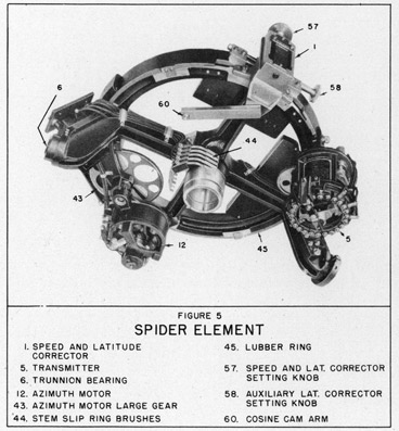
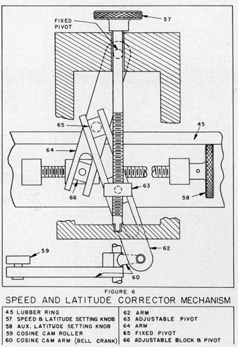
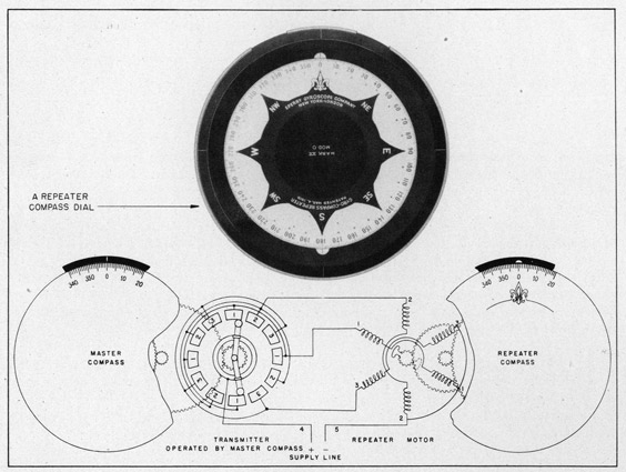
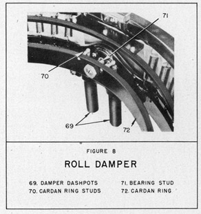 113. The compensation is made as follows: Suppose the Compass reading is 278 and it has been definitely established (by sun azimuths, bearings, etc.) that the Compass is 2° low. Simply loosen thumb nuts which clamp lubber line plate to lubber ring and shift
lubber line so that reading is 280. Reclamp plate. It is then necessary to change each repeater reading so that the repeaters are synchronized with the Compass. NOTE: If the plate is moved only a fraction of a degree, the repeater headings should be changed by loosening the transmitter on the Compass and shifting it as necessary to make repeater reading correspond to Compass reading.
113. The compensation is made as follows: Suppose the Compass reading is 278 and it has been definitely established (by sun azimuths, bearings, etc.) that the Compass is 2° low. Simply loosen thumb nuts which clamp lubber line plate to lubber ring and shift
lubber line so that reading is 280. Reclamp plate. It is then necessary to change each repeater reading so that the repeaters are synchronized with the Compass. NOTE: If the plate is moved only a fraction of a degree, the repeater headings should be changed by loosening the transmitter on the Compass and shifting it as necessary to make repeater reading correspond to Compass reading.