Instructions For Assembling And Disassembling Gun Barrels And Housings (Bayonet Joint Type), OD 2772, 1950, describes the best practices for installing and removing bayonet (interrupted thread) gun barrels from large guns.
In this online version of the manual we have attempted to keep the flavor of the original layout while taking advantage of the Web's universal accessibility. Different browsers and fonts will cause the text to move, but the text will remain roughly where it is in the original manual. In addition to errors we have attempted to preserve from the original this text was captured by optical character recognition. This process creates errors that are compounded while encoding for the Web.
Please report any typos, or particularly annoying layout issues with the Mail Feedback Form for correction.
1. The following instructions are intended for the guidance of Naval Shipyards, Ships in Service and Contractors when called upon to assemble or disassemble gun barrels and housings having the interrupted thread, or "bayonet joint" type of locking method. The sizes and marks of guns and housings having this locking feature are:
Size
Gun
Housing
First Group
5"/25 Cal.
Mk. 13 Mod 0
Mk. 3 Mod 0
5"/38 Cal.
Mk. 12 Mod 1
Mk. 1 and Mods
5"/54 Cal.
Mk. 16 Mod 0
Mk. 4 Mod 0
6"/47 Cal.
Mk. 16 Mod 0
Mk. 1 and Mods
6"/47 Cal.
Mk. 16 Mod 0
Mk. 3 Mods 4 and 5
8"/55 Cal.
Mk. 16 Mod 0
Mk. 1 Mods 0 and 1
Second Group
3"/50 Cal.
Mk. 19 Mod 0
Mk. 1
3"/50 Cal.
Mk. 21 Mod 0
Mk. 2 Mod 4
3"/50 Cal.
Mk. 22 Mod 0
Mk. 2 Mod 4
5"/25 Cal.
Mk. 17 Mod 0
Mk. 9 Mod 1
Third Group
3"/50 Cal.
Mk. 22 Mods 4 and 5
Mk. 8 Mods 1 and 2
2. The assembling or disassembling operatios may be required in order to:
(A) Make an initial assembly
(B) Make an inspection of joint condition
(C) Make a replacement of barrels.
3. The operations may be performed under one or a combination of the following working conditions:
(A) Ashore, in shop, with the use of a lathe (Housing and gun barrel removed from mount).
(B) Afloat or ashore, using cribbing and tackle, housing and gun barrel removed from mount.
(C) Afloat or ashore, using cribbing and tackle, housing not removed from mount.
3
4. The instructions which follow are, in general, divided into sections covering the various conditions under which the work may be performed.
5, Housing and Gun Barrel removed from mount - work performed in shop, using a lathe.
Assembly (5"/38 Cal. Gun Mk.12 Mod 1, Housing Mk. 1 and Mods)
A. Place housing on the tool carriage of a large lathe, with the gun socket towards the face plate and the keyway in the three o'clock position relative to the face of the plate. Align housing axis parallel with the tool carriage guides. Examine carefully all threads, bearing surfaces and keyway for burrs, grit or other foreign material. Check the fit between key and keyway.
B. Place two steady rests on the lathe carriage guides, one about 14" from the face plate, and the other in such location as will just clear the housing face and key after housing is in its final assembled position. Place gun barrel on the steady rests with keyway in the 4:30 o'clock position relative to the face plate. The thread portions on the barrel should now coincide with the blank spaces in the housing. Insert a block of wood between the face plate and gun muzzle to act as a stop and to prevent marring of gun muzzle. Examine all threads, bearing surfaces and keyway for burrs, grit, etc. Check the fit of key in the keyway.
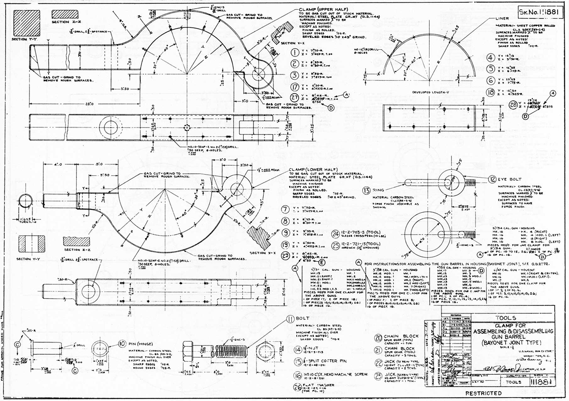
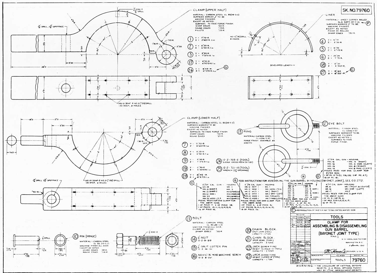
C. Assemble the applicable clamp and copper liner, shown on Ordnance Sketch No. 79760, or Sketch No. 111881, in a position, forward of the rear steady rest, such that the gun and clamp may be rotated one eighth of a turn, counter clockwise, relative to the face plate.
D. Check the alignment of housing and barrel by moving the lathe carriage, by hand, until the housing covers the gun barrel for the full length of its engagement. Clamp the housing securely to the carriage, and move carriage, with housing, back clear of the barrel.
E. Heat gun slushing compound, Grade A, 14C8 (Ord)
4
sufficiently to permit slushing it on the gun barrel and interior of the housing with a paint brush. While the compound is still hot, move the housing onto the gun barrel, forcing excess compound out through clearance spaces.
F. Rotate the barrel, engaging the threads of the barrel with those of the housing, until the keyways, are in alignment. Remove excess compound from keyways, using a narrow metal strip having a hooked end. Assemble the key. Pump slushing compound in at the Zerk fitting or fittings, located at top of housing, to fill all recesses completely. Wipe off all excess compound from exterior surfaces of barrel and housing.
6. Housing and gun barrel removed from mount, work performed in shop or on deck without use of lathe - assembly.
A. In general the same sequence of operations as above outlined should be followed, except that the gun and housing must be supported on cribbing, "V"-blocks or jacks and power to draw the gun and housing together must be supplied by tackle or screw jacks, depending upon the equipment at hand. It will probably by found necessary to apply the gun slushing compound sparingly prior to forcing the barrel home because of the power required to force out the excess. Depending upon the power available, it may even be found necessary to use oil only on the barrel and housing during the assembly operation. In either event, following the assembly and securing of the key, the internal recesses should be completely filled by pumping hot gun slushing compound Grade A, 14C8 (Ord) in through the Zerk fittings.
7. Housing not removed from mount - work performed afloat or ashore - disassembly and assembly.
Note: The following sequence of operations was followed by Mare Island Naval Shipyard when removing 5"/38 Caliber Gun Barrel Mark 12 Mod 1 from 5" Housing Mk. 1, in No. 1 Mount of the U.S.S. FARRAGUT. No difficulties were reported either in disassembling or reassembling the barrel. (See paragraph 9 also).
5
A. Place gun in zero elevation.
B. Bleed air from the counterrecoil system.
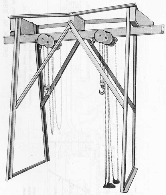
C. Place cribbing under the barrel and slide to support the gun horizontally, as shown on Ordnance Sketch No. 28640. Cover top of 12" x 12" timbers under the barrel with heavy grease and place two chocks, to support the barrel, on top of the greased surface of the cribbing. Block up slide, using 12" x 12" cribbing, to prevent excessive load on the elevating arc when removing barrel from housing.
D. Remove safety link.
E. Jack gun out of battery 7-1/2", using 10" screw jack to permit removal of gun and housing key.
F. Return gun to battery, using an 8" screw jack.
G. Check location lines for alignment.
H. Place the applicable assembling clamp, Sketch No. 79760 or Sketch No. 111881, in position 134" from the muzzle, sufficient distance forward of the shield to permit the extended arm of the clamp to clear the shield.
I. Take strain on clamp (in a counter clockwise direction, looking from muzzle), using a piece of pipe on the 1-5/8" round end of the assembling clamp. Before attempting to revolve the gun insure that the breech block is fully dropped, in order that the extractor nibs will be with drawn from the pockets in the gun; otherwise, extractors may be damaged or broken. Tap lightly with a 20 lb. sledge on the extended arm of clamp, to revolve and unlock.
J. Place wire strap aft of clamp and, using a 5-ton chain-fall, pull the gun forward 4', a sufficient distance to clean and inspect the threads of the gun housing.
K. Remove the heavy coating of gun slushing compound and replace it with a new coat.
6
L. Reinstall gun in housing by passing a pendant, toggled at muzzle through the bore of the gun and by attaching a 5-ton chain-fall to the structure of the ship at the rear of the gun slide.
M. When fully to the rear, maintain strain on the chain-fall and turn the assembling clamp clockwise until the location lines coincide.
N. Jack gun out of battery 7-1/2", install gun and housing key, and jack gun back to the battery position. Insert safety link.
8.
A. The foregoing will apply generally, to all of the gun and housing combinations listed under the First Group of paragraph 1, as, in each of these combinations the barrel may be removed from the front of the mount without removing the housing from its slide. It will be found necessary to remove the forward bearing block or bushing from the front of the slide before the gun barrel can be dismounted. Inspection of the individual mount will reveal these bearings. It is understood that modifications of the foregoing general instructions may be found necessary, due to differences in size, design and location of the different mount, barrel and housing combinations and to the availability of cribbing material and tackle.
B. The sequence of operations followed by a destroyer and tender in removal and replacement of a 5"/38 Cal. gun barrel is outlined in paragraph 9.
C. The 8"/55 Cal. Gun Mk. 16 Mod 0 consists of a tube and liner. Instructions for removing and installing the liner and tube are included in Ordnance Pamphlet No. 1180, Vol. 2 Chap. 3. Tools required are shown in Vol. 6 of Ordnance Pamphlet No. 1180.
D. Additional instructions for assembly and disassembly of gun barrels are included in Ordnance Pamphlets as follows:
7
Size
Gun
Housing
Ordnance Pamphlet
5"/54
Mk.16 Mod 0
Mk.4 Mod 0
O.P. 1027 - Chap. 2
6"/47
Mk.16 Mod 0
Mk.1 & Mods
O.P. 592 - Chap. 2
6"/47
Mk.16 Mod 0
Mk.3 Mods 4&5
O.P. 760 - Chap. 3
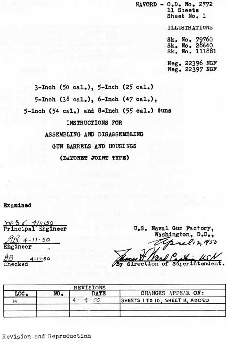
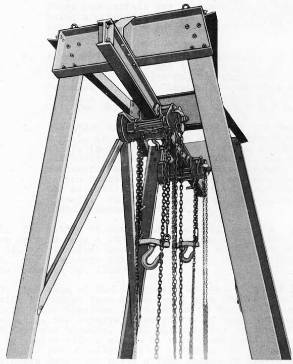
9. The following sequence of operations was followed by the U.S.S. DOBBIN in the process of disassembly and reassembly of the 5"/38 caliber gun barrel single mount (1500 ton destroyers). This was accomplished by means of the regunning rig shown on the copies of Naval Gun Factory Negatives No. 2239 and No. 22397. It is believed that with this rig, the procedure described is also applicable to the 5"/38 caliber twin mounts with the exception of the high mounts which may require some minor additional shoring.
A. Tender - Provide additional wedges to allow the pressure on the frame wooden deck support pieces to be equally distributed over the destroyer's deck framing.
B. Prior to going alongside the tender for regunning, the following preparations should be made:
(1) Destroyer - Prepare gun to be disassembled as follows:
(a) Remove gun mount training limit stops.
(b) Remove forward bearing.
(c) Remove locking stud and key.
(d) Put gun on 0° elevation and block up beneath breech housing.
(e) See centering pin is in.
(f) Jack gun out of battery; remove keep stud and locking key.
(g) Jack gun back into battery.
(h) Drop breechblock.
(i) Move all deck gear (lockers, reels, etc.) clear of space to be occupied by regunning gear.
(j) Remove awning and strongback from above gun.
(k) Remove watershed (on guns with which fitted).
(l) Provide guys and steadying lines.
(m) Provide torpedo truck.
(n) Provide battery tools and 1 crow-bar.
8
(2) Tender - Prepare as follows:
(a) Assemble regunning gear frame on part of deck approximately abreast destroyer gun to be disassembled, and convenient to cargo boom.
(b) Disconnect one end of A-frame tie bars to permit frame to be lowered directly over the gun.
(c) Get boom and deck machinery ready for running.
(d) Provide:
2 - 2 1/4" open end wrenches
1 - 1-1/8" open end wrench
1 - 16" screwdriver
1 - 12 lb. sledge hammer
1 - barrel wrench
1 - One ton chain fall (for returning gun barrel to housing)
2 - Torpedo hoisting straps
2 - Hydraulic jacks 12 1/2 ton capacity, 8" rise.
1 - Timber 6" x 6" x 4 1/2'
C. Upon going alongside (directly next to tender):
(1) Destroyer
(a) Adjust herself alongside in position that boom carrying the regunning gear can plumb the gun to be disassembled.
(b) Put herself on an even keel.
(2) Tender
(a) Lower regunning gear to straddle the gun.
D. With regunning gear in position proceed with the disassembly as follows:
(1) Connect free end of A-frame tie bars.
(2) Put jacks between base timbers and gun undercarriage.
(3) Secure framing from possible tipping by guys.
(4) Install barrel wrench on gun barrel just inboard of its center of gravity, handle to tho left (facing muzzle), and making approximately a 45° angle with the deck.
9
(5) Hook track chain falls to gun tube lifting straps one inboard of the barrel wrench, the other near the center of the barrel (do not take a strain).
(6) With sledge hammer tap wrench handle (counter-clockwise when facing muzzle) until scribe mark on the left face of breech housing lines up with the housing scribe mark.
(7) Take slight strain on after chain.
(8) Move and lock forward chain fall well forward of bight of its hoisting strap and take a strain (for pulling effect).
(9) Place a 6" X 6" X 4 1/2" timber against face of breech and tap with sledge hammer to start gun out of housing.
(10) Run chain falls as far out on track as possible and lock. If barrel is to be only inspected, replace in reverse order.
E. If barrel is to be replaced continue as follows:
(11) Place torpedo truck inside frame and beneath gun; lower gun carefully into truck cradle and secure truck with guys against any motion.
(12) Disconnect one end of A-frame tie bar.
(13) Cargo boom pick up regunning gear frame clear of barrel and set down on deck clear of barrel.
(18) Reassemble new barrel and breech housing as indicated above for inspection.
NOTE: Should deck beneath torpedo truck give an indication of weakening during performance of step 11, immediately pick up barrel on the chain falls and use shoring underneath section of deck affected.
10
10.
A. The gun barrel and housing combinations listed as the second group of paragraph 1, differ radically from those of the first group in that the barrels are not removable from the front of the mount and some of the housings are not supported in the slide. It is not possible to exchange barrels in these mounts without dismounting the housing. These gun barrels may be assembled in the housings using a procedure similar to that described in paragraph 5 and 6 and disassembled using a reverse procedure.
B. Assembly of the 3"/50 Cal. Gun Mk. 21 or Mk. 22 and Housing Mk. 2 Mod 4 in the slide is described in Ordnance Pamphlet No. 811 Chapter 2. Ordnance Pamphlet No. 1029, Chapter 2, describes the assembly and disassembly procedure for 5"/25 Cal. Gun Mk. 17 and Housing Mark 9 Mod 1.
C. The 3"/50 Caliber Gun Mark 19 and its Housing, Mark 1, is a combination made of copper-nickel alloy, (monel metal), therefore no corrosion difficulties should be encountered. It will be necessary, however, to maintain adequate lubrication between the gun barrel and housing during the assembly operation to prevent galling of the threads. For this purpose use anti-seize compound Ordnance St'd. No. 53.
11. The method of assembling and disassembling the 3"/50 cal. Gun Mark 22 Mods 4 and 5 and Housings Mark 8 Mods 1 and 2, (Group 3), is dependent upon the slide in which they are installed. For procedure and tools required refer to Chapter 4 Ordnance Pamphlet No. 1566.
12. The tube of the 8"/55 cal. Gun Mk. 16 Mod 0 is provided with a contact face which bears on a similar surface on the housing when the tube is assembled in the housing and rotated to align the keyways, thus providing draw between the contact face and threads. This assembly may require that the wrench be tapped with a sledge to rotate tube and drive the tube home for proper alignment of keyways. If after reasonable attempts have been made, a tube cannot be driven home, retract the tube and polish the breech end bearing surface of tube with emery cloth. Reassemble after cleaning all parts thoroughly. The above noted draw is not provided on the other guns and housings included in this O.D.
13. In assembly of all of the above noted guns except the 3"/50 Gun Mark 19 referred to in paragraph 10C, gun
11
slushing compound Grade A, 14C8 (Ord), is to be used as a preservative against corrosion between the threads of the gun and housing.