Twin 20-mm Antiaircraft Assemblies, OP 1439, 1945, is a Navy service manual for the twin mount version of the classic WW II anti-aircraft gun on the tripod style mount.
In this online version of the manual we have
attempted to keep the flavor of the original layout while taking advantage
of the Web's universal accessibility. Different browsers and fonts will cause
the text to move, but the text will remain roughly where it is in the original
manual. In addition to errors we have attempted to preserve from the original
this text was captured by optical character recognition. This process creates errors that are compounded while encoding for the Web.
Please report any typos, or particularly annoying layout issues with the Mail Feedback Form for correction.
20-mm A. A. ASSEMBLIES (TWIN)
20-mm A. A. GUN MOUNTS MARK 20 AND MODS
20-mm A. A. GUN MOUNTS MARK 24 AND MODS
20-mm SHOULDER RESTS AND HANDLE BARS MARK 8 MOD 0
20-mm SIGHT ADAPTER EQUIPMENT MARK 2 MOD 0
20-mm MACHINE GUN MECHANISM MARK 4 MOD 1
20-mm MAGAZINE MARK 5 MOD 0
28 APRIL 1945
2
NAVY DEPARTMENT
BUREAU OF ORDNANCE
WASHINGTON. D. C.
28 April 1945
ORDNANCE PAMPHLET 1439
20-mm ANTIAIRCRAFT ASSEMBLIES (TWIN)
1. Ordnance Pamphlet 1439 describes the construction, operation, and maintenance of the twin 20-mm A.A. Assemblies, including the following components: 20-mm A.A. Gun Mounts Mark 20 and Mods; 20-mm A.A. Gun Mounts Mark 24 and Mods; 20-mm Shoulder Rests and Handle Bars Mark 8 Mod 0; 20-mm Sight Adapter Equipment Mark 2 Mod 0; 20-mm Machine Gun Mechanism Mark 4 Mod 1; and 20-mm Magazine Mark 5 Mod 0.
2. Additional publications relative to the use of 20-mm A.A. Assemblies include Ordnance Pamphlet 909 and Ordnance Pamphlet 911. Another publication to which reference may be made is Ordnance Pamphlet 1040 (Preliminary).
3. This pamphlet does not supersede any existing publication.
G. F. HUSSEY, JR. Rear Admiral, U. S. Navy Chief of the Bureau of Ordnance
3
PREFACE
This Ordnance Pamphlet describes the construction, operation, and maintenance of the various components of two types of twin 20-mm Assemblies.
The Gun Mounts Mk 20 and Mods are fixed-trunnion-height mounts carrying two guns. The general construction is similar to the Gun Mounts Mk 24 and Mods. Only a very limited number of these gun mounts were built, and they have been superseded by the Gun Mounts Mk 24 and Mods. Spare parts, other than those furnished with the mounts, or those which are used on other gun mounts, are not available. For these reasons, very little space in this pamphlet has been devoted to this gun mount.
The Gun Mounts Mk 24 and Mods are fixed-trunnion-height mounts carrying two guns. They are similar to the Gun Mounts Mk 20 and Mods but have an improved cam limit stop and other minor constructional differences. The general construction of these gun mounts is much like that of the Gun Mounts Mk 10 and Mods, but many details are different, as required to carry two guns.
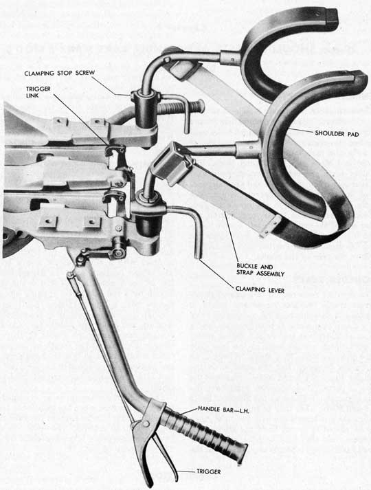
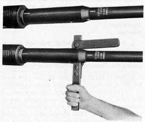
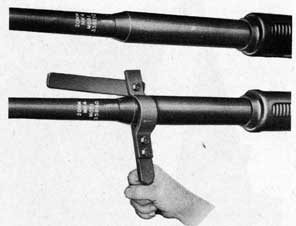
The Shoulder Rests and Handle Bars Mk 8 Mod 0 are designed for use on the twin 20-mm gun mounts. Their outstanding characteristic is the fact that they are fastened to the gun-mount cradle instead of to the gun. The left handle bar is fitted with a trigger for firing the guns.
The Sight Adapter Equipment Mk 2 Mod 0 is used to support the Gun Sight Mk 14 Mods 2 or 6 on the 20-mm Gun Mounts Mk 20 and Mods and Mk 24 and Mods.
The 20-mm Machine Gun Mechanism Mk 4 Mod 1 is the gun used on the twin mounts. It differs from the Mechanism Mk 4 Mod 0 in only two parts, and in general it requires the same maintenance as the older gun.
The Magazine Mk 5 Mod 0 is similar to the Magazine Mk 4 Mod 0, but its shape is reversed so that it can be used on the left-hand gun on twin gun mounts.
An illustrated parts list for the various components listed above is located at the rear of this pamphlet, together with a part-number index.
4
Prepared for the Bureau of Ordnance by
Pontiac Motor Division
General Motors Corporation
Pontiac, Michigan
Machine Gun Mechanism Mk 4 Mod 1 (2 Mechanisms required)
105. Pounds
Gun Barrels Mk 4 Mods 0 and 1
Solid Barrel (2 Barrels required)
44.7 Pounds
Ribbed Barrel
37.3 Pounds
Total weight of above components (Solid barrels and Gun Mount Mk 24 Mod 5)
1216. Pounds
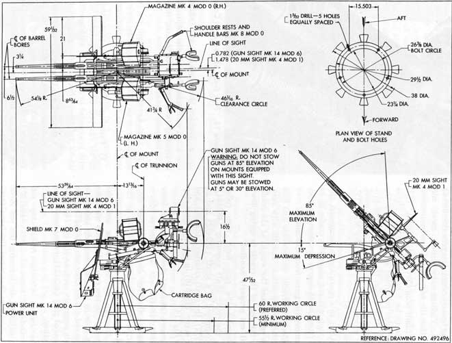
For other characteristics see Working Circle Drawing, No. 492496.
* Train limited by the length of power cable when mount is equipped with a Gun Sight Mk 14 Mods 2 or 6.
20-mm SHOULDER RESTS AND HANDLE BARS MARK 8 MOD 0
Use
Gun Mounts Mk 20 and Mods and Mk 24 and Mods
Weight-Shoulder Rests
19.8 Pounds
-Handle Bars
12.7 Pounds
-Total
32.5 Pounds
13
20-mm SIGHT ADAPTER EQUIPMENT MARK 2 MOD 0
Use
Supporting Gun Sights Mk 14 Mods 2 or 6 on Gun Mounts Mk 20 and Mods and Mk 24 and Mods
Weight
25.7 Pounds
20-mm MACHINE GUN MECHANISM MARK 4 MOD 1
Use
Gun Mounts Mk 20 and Mods and Mk 24 and Mods
Weight
105 Pounds
20-mm MAGAZINE MARK 5 MOD 0
Capacity
60 Rounds
Weight-Empty
31 Pounds
-Loaded
63 Pounds
TWIN 20-mm A.A. GUN MOUNT COMPONENTS
Gun Mount
Stand
Carriage
Cradle
Shields
Type
Mk 20 Mod 0
Mk 7 Mod 9
Mk 16 Mod 0
Mk 13 Mod 0
Mk 6 Mod 0
FIXED (Tripod)
Mk 20 Mod 1
Mk 7 Mod 10
Mk 16 Mod 0
Mk 13 Mod 0
Mk 6 Mod 0
FIXED (Tripod)
Mk 20 Mod 2
Mk 7 Mod 11
Mk 16 Mod 0
Mk 13 Mod 0
Mk 6 Mod 0
FIXED (Tripod)
Mk 24 Mod 0
Mk 7 Mod 12
Mk 18 Mod 0
Mk 14 Mod 0
Mk 7 Mod 0
FIXED (Tripod)
Mk 24 Mod 1
Mk 7 Mod 13
Mk 18 Mod 0
Mk 14 Mod 0
Mk 7 Mod 0
FIXED (Tripod)
Mk 24 Mod 2
Mk 7 Mod 14
Mk 18 Mod 0
Mk 14 Mod 0
Mk 7 Mod 0
FIXED (Tripod)
Mk 24 Mod 3
Mk 7 Mod 21
Mk 18 Mod 0
Mk 14 Mod 0
Mk 7 Mod 0
FIXED (Tripod)
Mk 24 Mod 4
Mk 7 Mod 22
Mk 18 Mod 0
Mk 14 Mod 0
Mk 7 Mod 0
FIXED (Tripod)
Mk 24 Mod 5
Mk 7 Mod 23
Mk 18 Mod 0
Mk 14 Mod 0
Mk 7 Mod 0
FIXED (Tripod)
Note-Shields are not a gun mount component. They are shown above for identification purposes on those assemblies which include shields.
14
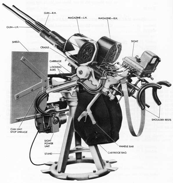
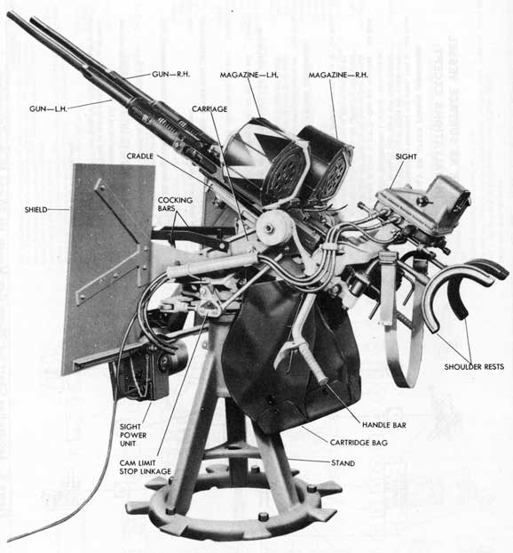
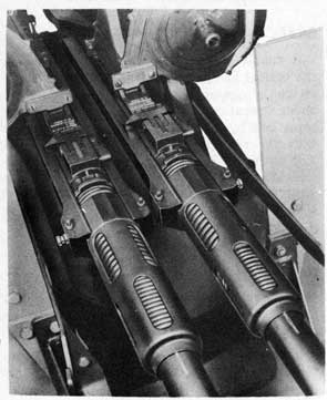
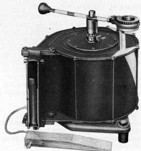
Figure 1. Exterior View showing General Arrangement
of the Twin 20-mm A.A. Gun Mount Mk 20 Mod 2.
15
Chapter 2 20-mm A.A. GUN MOUNTS MARK 20 AND MODS DESCRIPTION
GENERAL DESCRIPTION
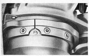
This gun mount (see Fig. 1) is a fixed-trunnion-height mount carrying two non-synchronized guns. The guns are trained both by handle bars and by shoulder rests. Both guns are fired by a trigger on the left handle bar. The construction details are similar to those of the Mounts Mk 24 Mods 0, 1, and 2. The main differences between the Gun Mounts Mk 20 and Mods and the Gun Mounts Mk 24 and Mods are the mechanical details of the cam limit stop mechanism. Comparison of Figs. 2 and 3 with Figs. 7 and 8 will show how these mechanisms differ, although both employ a flat, plate-type cam with a roller follower bearing on the periphery of the cam. It should be noted that the cam limit stop lever, shown in Fig. 2, passes through a slot in the shield bracket if shields are used, as shown in Fig. 3.
The guns can be elevated from 15 degrees below horizontal (depression) to 85 degrees above horizontal. The guns and the cradle can be locked at elevations of five or 85 degrees by the cradle lock on the right side of the carriage. The guns can be trained through an unlimited angle, unless stopped by the power cable of a Gun Sight Mk 14 Mod 6. They are locked in train by a carriage lock lever on the right side of the forward end of the carriage.
STAND MK 7 MODS 9, 10, AND 11
Three modifications of the Gun Mounts Mk 20 and Mods have been assigned. All three consist of variations in the stand. These variations
include two trunnion heights and two types of weldment construction. Gun mounts assembled with these variations are designated as follows:
Mount
Stand
Trunnion Height
Mk 20 Mod 0
Mk 7 Mod 9
52 1/2 inches
Mk 20 Mod 1
Mk 7 Mod 10
52 1/2 inches
Mk 20 Mod 2
Mk 7 Mod 11
47 1/32 inches
The pivot and pivot thrust bearings used in all three stands are the same as used in the Gun Mounts Mk 10 and Mods. The thrust bearings are two pairs of semicircular steel rings faced with babbitt. They are greased by a pressure oiler in the cup at the top of the pivot in the same manner as on the Gun Mounts Mk 10 and Mods.
CARRIAGE MK 16 MOD 0
This carriage is very similar to the carriage used on the Gun Mounts Mk 24 and Mods. The main difference is in the construction of the cam limit stop. The weight of the guns is balanced by a pair of cradle spiral springs, one on each side of the carriage.
CRADLE MK 13 MOD 0
Made wider than the cradles on single gun mounts, in order to carry the two guns, the main difference between this cradle and the one used with the Gun Mounts Mk 24 and Mods is in the cam limit stop attachment at the cradle.
16
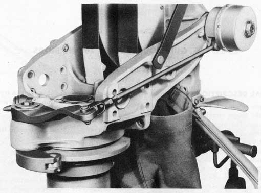
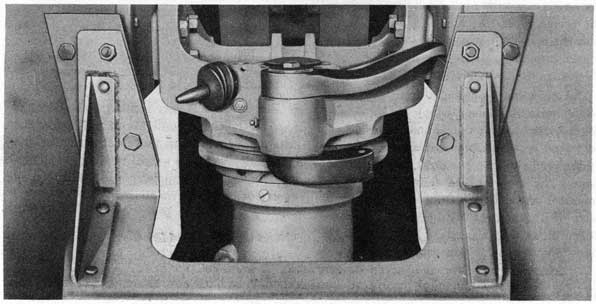
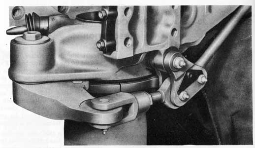
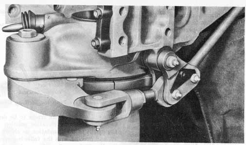
Figure 2. Cam Limit Stop Mechanism. (The Cam Blanks have not been Profiled.)
Figure 3. Cam Limit Stop Parts on Carriage.
(Note Lever passing through Slot in Shield Bracket.)
17
LUBRICATION
GENERAL LUBRICATION
For general lubrication of the gun mount and guns, see Lubrication Chart-Fig. 4, for surface vessel installations and Lubrication Chart -Fig. 5, for submarine installations.
STAND
Three pressure oilers are used to lubricate the pivot bearing surfaces. These oilers are located as follows: one in the cup in the top of the pivot, under the rubber pivot cover; one on the side of the pivot housing in a notch in the bottom of one of the cam plates; and one on the side of the stand sleeve, near the bottom. After initial greasing when the mount is assembled, lubrication at each of the three oilers should be accomplished by using grease gun (299832-1) with bearing grease OS-1350. Rotate the pivot while lubricating.
Coat the edge of the cam plates and the roller with bearing grease OS-1350. Paint will not stay on the cam surface because of the high contact pressures between the roller and the cams.
CARRIAGE
Five pressure oilers are used on the carriage for lubricating its bearings. There is an oiler on
the outside of each trunnion arm just forward of the cradle spiral spring case; one at the cradle lock lever; one at the carriage lock lever; and one on the boss that carries the cam limit stop lever. These points should each be lubricated with bearing grease OS-1350, using several strokes of grease gun (299832-1). Work each bearing while it is being lubricated.
The three bearing joints in the cam limit stop linkage, the cocking-bar axis pins, and the cradle and carriage lock-lever axis pins should be oiled with light preservative oil OS-1362. It will be necessary partially to remove the rubber bellows to get at the two lock lever axis pins.
CRADLE
The two gun-securing bolts and two bearings of the cradle trigger mechanism are fitted with pressure oilers. Each of these points should be lubricated with several strokes of the grease gun (299832-1) using bearing grease OS-1350. The balance of the joints of the trigger mechanism should be oiled with light preservative oil OS-1362.
The cartridge-bag support hinges and frame hinges and the cartridge weight-band pivots should be oiled sparingly with light preservative oil OS-1362.
MAINTENANCE
STRIPPING, ASSEMBLY AND INSTALLATION
The procedure for these operations as covered for the Gun Mounts Mk 24 and Mods in Chapter 3 will be a sufficient guide for performing the same operations on the Gun Mounts Mk 20 and Mods.
The general arrangement of the gun mount and its parts is shown on Plate 1-Sectional Details of Gun Mount-at end of this pamphlet.
653659 O-45-3
For converting Bureau of Ordnance part numbers to OE part numbers, in order to find parts stocked under OE numbers for older mounts, refer to Parts List or Numerical Index at the rear of this pamphlet, or to Cross Index List of Part Numbers on page 201 of OP 909 (March 1943 issue) or on page 215 of OP 911 (March 1943 issue). It should be noted that some parts do not have an OE part number, and are identified only by Bureau of Ordnance part numbers.
18
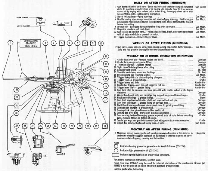
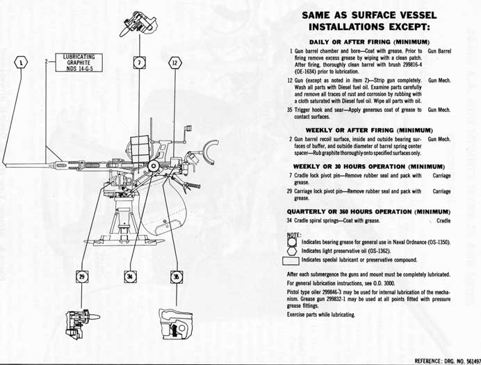
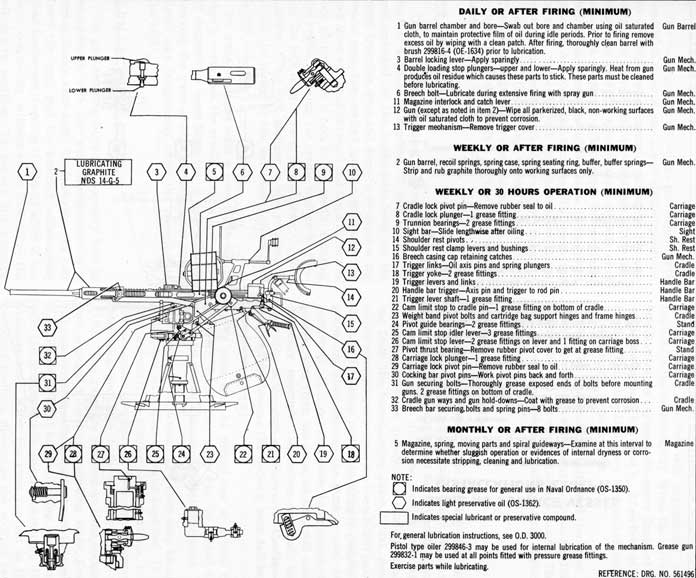
Figure 4. Lubrication Chart for 20-mm Gun Mounts Mk 20 and Mods-Surface Vessels.
19
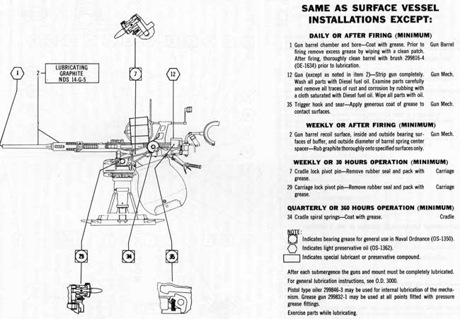
Figure 5. Lubrication Chart for 20-mm Gun Mounts Mk 20 and Mods-Submarines.
20
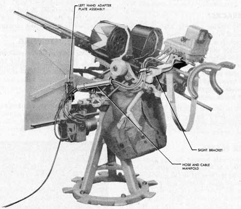
Figure 6. Exterior View showing General Arrangement
of the Twin 20-mm A.A. Gun Mount Mk 24 Mod 5.
21
Chapter 3 20-mm A.A. GUN MOUNTS MARK 24 AND MODS DESCRIPTION
GENERAL DESCRIPTION
This gun mount (see Fig. 6) is a fixed-trunnion-height mount carrying two non-synchronized guns. The general construction is similar to the Gun Mounts Mk 10 and Mods, and a number of parts are common to both mounts. The guns are trained both by handle bars and by shoulder rests, with the guns being fired by a trigger on the left handle bar. The mount is equipped with a cam limit stop to prevent training or depressing the guns into a position that would permit firing into the ship's structure or equipment. Six Mod designations have been assigned, as covered on page 23.
The guns can be elevated from 15 degrees below horizontal (depression) to 85 degrees above horizontal. The guns and the cradle can be locked at elevations of five degrees, 30 degrees, or 85 degrees by the cradle lock on the right side of the carriage. The guns can be trained through an unlimited angle, unless stopped by the power cable of a Gun Sight Mk 14 Mod 6. They are locked in train by a carriage lock lever on the right side of the forward end of the carriage.
STANDS MK 7 MODS 12, 13, 14, 21, 22, AND 23
The general construction of the stand follows that used for the Mounts Mk 10 and Mods. The stand is of the tripod type and is made up of various stamped or rolled steel pieces welded into a stand weldment. The weldment has a base ring at its lower end, drilled for bolts for attaching the mount to the deck, and a sleeve at its upper end which is machined to receive the pivot housing.
The pivot housing serves as a bearing for the pivot and carries the pivot thrust bearings. The upper end of the pivot housing is threaded
to receive the pivot retainer, which is the same as used on the Gun Mounts Mk 5 and Mods and Mk 10 and Mods. The retainer is secured by a lock screw threaded into the pivot housing. The lower end of the pivot housing is closed with a steel cap and a gasket, secured to the pivot housing by bolts and lock washers. A hole in the cap is normally closed with a pipe plug, but the plug should be removed when the mount is installed on a submarine.
The pivot is the same as used in the Gun Mounts Mk 10 and Mods. Two types of pivot-thrust lower bearings are released. The first type is a pair of semicircular steel rings faced with babbitt. These are the same as used in the Gun Mounts Mk 10 and Mods. The second type bearing is a separable ball bearing consisting of two races and a ball and separator assembly. This ball bearing is mounted under the flange of the pivot and requires a pivot housing with a deeper recess than when the babbitt bearing is used. The pivot thrust upper bearing is babbitt-faced steel in all of the stands.
The pivot housing is retained in the stand weldment by a draw bolt secured with a nut and lock washer. The cam plates of the cam limit stop are fastened to the pivot housing above the stand weldment with eight screws and a pair of dowel pins. These cams carry considerable loads if the guns are stopped by the cams when being trained rapidly, so a pair of large dowel screws are threaded through the weldment and into close-fitting holes in the pivot housing. These dowel screws prevent the pivot housing from turning in the weldment and aid the draw bolt in holding the pivot housing in the stand weldment.
Six modifications on the Gun Mount Mk 24 have been assigned. All six consist of variations in the stand. These variations include two trunnion heights, two types of construction of
22
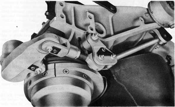
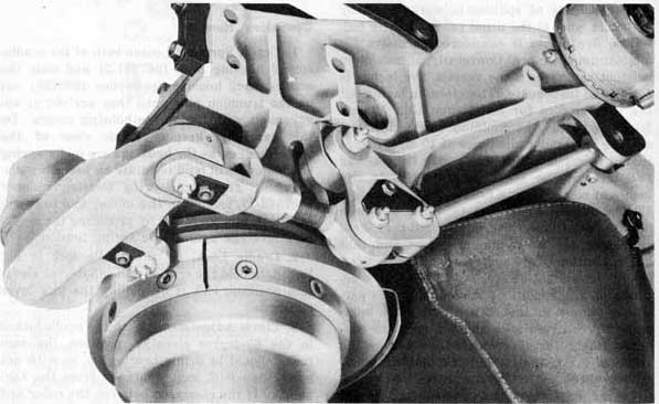
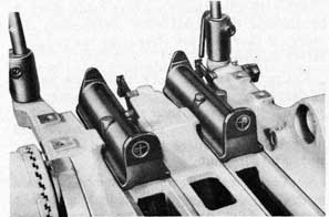
Figure 7. Cam Limit-Stop Parts Mounted on Carriage.
(The Cams have been Profiled.)
Figure 8. Cam Limit-Stop Parts Mounted on Carriage.
(Note the Cam Profile.)
23
the weldment, and two types of pivot thrust lower bearings. Mounts assembled with these variations are designated as follows:
Mount
Stand
Trunnion Height
Pivot Thrust Lower Bearing
Mk 24 Mod 0
Mk 7 Mod 12
52 1/2 in.
Babbitt
Mk 24 Mod 1
Mk 7 Mod 13
52 1/2 in.
Babbitt
Mk 24 Mod 2
Mk 7 Mod 14
47 1/32 in.
Babbitt
Mk 24 Mod 3
Mk 7 Mod 21
52 1/2 in.
Ball
Mk 24 Mod 4
Mk 7 Mod 22
52 1/2 in.
Ball
Mk 24 Mod 5
Mk 7 Mod 23
47 in.
Ball
CARRIAGE MK 18 MOD 0
The carriage is similar to the carriage used on the Gun Mounts Mk 10 and Mods, but is wider across the trunnion arms in order to span two guns. Two cradle spiral springs, located one on each side of the carriage, are used to balance the guns. A pair of cocking bars are attached to bosses on the carriage by spring loaded pivot pins. The cocking bars rest in clips at the forward end of the carriage when not in use. The carriage and cradle locks are similar to those used on the Gun Mounts Mk 10 and Mods, although mechanical details of the pieces are somewhat different.
The cam limit stop parts are attached to the carriage and stand as shown in Figs. 7 and 8. The lever is carried by a boss at the front of the carriage and the other parts by a boss at the left side of the carriage. The cams are bolted and dowelled to the stand. All moving parts of the mechanism are fitted with pressure oilers. When the cams are correctly shaped, depressing the guns causes the roller to bear on the cams. This prevents further depression of the guns and firing into the ship or its equipment. If training is attempted from a clear area into an obstructed area, the roller bears on the cams and elevates the guns above the obstruction. In certain cases, where the obstruction has very high and steep sides and the guns are being moved in train at very low elevations, the guns may be brought to an abrupt stop without lifting over the obstruction.
CRADLE MK 14 MOD 0
The cradle, which carries the two guns, is supported by the carriage on two trunnion pins. Both pins are keyed to the cradle, and both are engaged with cradle spiral springs at their outer ends. Each gun rests in a machined groove in the cradle and is retained there by the gun-securing bolts at the front of the cradle. Bosses are provided at the rear of the cradle for attaching the bracket for the Gun Sight Mk 14 Mod 6.
The cradle differs from previous ones in five major respects: including the mounting of two guns; the attachment of a portion of the trigger mechanism to the rear of the cradle; the attaching of the shoulder rests to the cradle; the method of attaching the cam limit stop mechanism to the cradle; and the size and shape of the cartridge bag and its method of attachment to the gun mount.
The guns are mounted in the cradle side by side, with their barrel bore axes located vertically on the center line of the trunnion pins. The guns are spaced 6 1/2 inches apart, each gun being 3 1/4 inches out from the center of the carriage pivot. The gun ways machined in the cradle are parallel within the limits of manufacturing practice, so that the guns fire parallel. The gun-securing-bolt parts are the same as used in previous mounts and hold the guns in the cradle in the same manner.
The trigger parts and firing mechanism are covered in detail in Chapter 4 under Shoulder Rests and Handle Bars Mk 8 Mod 0. Certain parts of the firing mechanism are attached to the rear end of the cradle and actuate the two breech-casing triggers. These trigger parts are actuated by the handle-bar trigger through an idler lever. They are connected to the guns by snap links, which allow speedy uncoupling of the parts if it is necessary to remove one of the guns from the mount. Either gun can be removed from the cradle without disturbing the other gun. To remove a gun, it is only necessary to unsnap the two trigger links, flip the trigger yoke to the rear and down, withdraw the gun securing bolt, slide the gun to the rear, and lift it from the cradle.
The shoulder rests and handle bars are described in detail in Chapter 4. These parts are
24
carried on the cradle of the twin mounts instead of on the breech casing as on older mounts.
Machined bosses and tapped holes are provided on the under side of the cradle for attaching the handle bars. A pair of bosses on the rear outer corners of the cradle are machined to fit the shoulder-rest frame brackets.
The cam limit stop rear rod is attached to the cradle below the left trunnion pin. A slot is machined in the under side of the cradle, and the rear end of the rod enters into the slot and is retained there by a pin. The pin is retained in its hole in the cradle by a drive pin. A pressure oiler to lubricate the bearing joint is fitted
in a hole on the under side of the cradle.
A single large cartridge bag, having a capacity of 840 empty cartridge cases (14 magazines), is carried under the cradle. The flaps at the bottom of the bag for emptying the bag are considerably larger than those on bags on single gun mounts. The bag is fastened to the cradle and carriage with two straight pivot bolts. These bolts are retained by washers and cotter pins at both ends. Two cartridge weight bands and two pairs of cheek plates guide the empty cartridge cases from the guns into the bag. The cheek plates are fastened to the cradle with self-locking screws.
LUBRICATION
GENERAL LUBRICATION
Routine lubrication of the gun mount and guns should be carried out as specified on Lubrication Chart-Fig. 9, for surface vessel installations and on Lubrication Chart-Fig. 10, for submarine installations.
STAND LUBRICATION
The pivot bearing surfaces in the stand are lubricated by three pressure oilers. One of these oilers is in the recess in the top of the pivot, under the rubber pivot cover, and lubricates the pivot thrust bearings. The other two oilers lubricate the pivot side-bearing surfaces. One oiler is in the side of the pivot housing, located between the ends of the cam plates, and the other is on the side of the stand sleeve, just above the bottom of the sleeve. After initial greasing at the time of mount assembly, lubrication at each of the three oilers is done with grease gun (299832-1), using bearing grease OS-1350. The pivot should be rotated while it is being lubricated. The foregoing procedure is to be followed for all mounts, whether equipped with plain or ball-type thrust bearings.
Coat the edge of the cam plates and the roller with bearing grease OS-1350 to prevent corrosion. Painting this surface is not satisfactory, because the paint will scale off on account of the high pressures between the cam plates and the follower roller.
CARRIAGE LUBRICATION
Ten pressure oilers are located on the
carriage and cam limit stop parts. There is an oiler on the outside of each trunnion arm just forward of the cradle spiral spring case; one at the cradle lock lever; one at the carriage lock lever; one on the carriage boss that carries the cam limit stop lever; two on the cam limit stop lever; and three on the cam limit stop idler lever. Each of these points should be lubricated with several strokes of grease gun (299832-1), using bearing grease OS-1350. Work each bearing while it is being lubricated.
The cocking-bar axis pins and the cradle and carriage lock-lever axis pins should be oiled with light preservative oil OS-1362. The rubber bellows must be partially removed to gain access to the lock-lever axis pins.
CRADLE LUBRICATION
The gun-securing bolts and two bearings of the cradle trigger linkage are fitted with pressure oilers. The axis pin which attaches the cam limit stop rear rod to the cradle is also fitted with a pressure oiler, located on the under side of the cradle in line with the axis bolt. Lubricate each of these points with bearing grease OS-1350, using grease gun (299832-1). The other bearing points of the cradle trigger linkage should be oiled with light preservative oil OS-1362.
The cartridge weight-band pivots and the cartridge-bag support hinges and frame hinges should be oiled sparingly with light preservative oil OS-1362.
25
Figure 9. Lubrication Chart for 20-mm Gun Mounts Mk 24 and Mods-Surface
26
Figure 10. Lubrication Chart for 20-mm Gun Mounts Mk 24 and Mods-Submarines.
27
OPERATION
CARRIAGE LOCK
The carriage lock allows the gun mount to be secured in train at any one of sixteen positions. To lock the mount in train, lift up on the carriage-lock lever at the forward end of the carriage and turn the guns in train slightly until the lever snaps up. This forces the carriage-lock plunger into one of the holes in the pivot retainer and locks the carriage. To unlock the carriage, force the lock lever downward, thereby withdrawing the lock plunger from the pivot retainer, and the carriage is free to be trained. The lock plunger will retain its position, either locked or unlocked, as it is engaged by a spring-loaded detent ball.
CRADLE LOCK
The cradle lock secures the cradle at elevations of 5, 30, or 85 degrees. To lock the cradle, pull outward on the cradle-lock lever on the right trunnion arm and elevate or depress the cradle past the desired locking position. The lock lever will snap outward and force the cradle lock plunger into a hole in the cradle, securing the cradle. Freeing the cradle is done by forcing the lock lever inward, to withdraw the lock plunger. This lock plunger is also retained in either the locked or the unlocked position by a detent ball.
On guns equipped with a Gun Sight Mk 14 Mod 6, never lock the cradle at elevations above 30 degrees for more than one or two minutes. Leaving the guns at high elevations for longer times may temporarily affect the operation of the sight.
GUN-SECURING BOLTS
The gun-securing bolts are normally kept in engagement with the gun mechanisms by a spring inside each bolt. To disengage the bolt from the gun, pull the knurled withdrawing head downward, turning it slightly after it has been completely withdrawn to lock it in the withdrawn position. To engage the securing bolt with the gun mechanism, turn the withdrawing head until it unlocks and springs upward into the gun. The bolt will sometimes
move upward until it strikes the bottom of the breech casing but not into engagement with the hole in the breech casing. When the securing bolt is correctly engaged, the upper flange of the withdrawing head is within 1/16 of an inch of the cradle. This should always be checked before firing a newly mounted gun.
Coat the gun-securing bolts and the holes in the breech casings with bearing grease OS-1350 when the guns are installed on the mount. This will prevent corrosion or galling of the mating surfaces.
COCKING BARS
Cocking the Guns. The cocking bars are lifted out of engagement with their clips and allowed to fall down inside the trunnion arms. Depress the guns until the cocking bars can be hooked over the gun-cocking studs protruding from the barrel-spring cases. Push down on the shoulder rests until the breech-bolt pawls are heard to snap under the trigger parallelogram, and then depress the guns to near the horizontal. It is not necessary to uncouple the cocking bars from the guns, as they will automatically uncouple themselves and fall into their clips as the guns are depressed. Caution-Keep hands free as the cocking bars fall into their clips.
The guns may be cocked one at a time by one man, or the two guns may be cocked together if two or more men elevate the guns.
Uncocking the Guns. The guns may be uncocked one at a time or both together. It is first necessary to remove the magazines, trip the magazine catches to free the magazine interlocks, and turn both safe/fire levers to FIRE. The guns are elevated and the cocking bars engaged with the gun-cocking studs. Keep the guns elevated sufficiently to insure the cocking bars being tight on the cocking studs, and pull the trigger while bearing down on the shoulder rest. After the guns run out to the uncocked position, disengage the cocking bars from the cocking studs and replace them in the cocking-bar clips. Lock the guns at the five-degree or 30-degree elevation position.
28
Breech-Block Stripping. To replace the cotter, hammer axis bolt, hammer, or striker pin, without removing the gun from the cradle, proceed as follows. The gun to be worked on should be uncocked, and the other gun may be cocked or uncocked.
Operation Number
1. Engage cocking bar with the gun, elevate to five-degree elevation position, and lock there with the cradle lock.
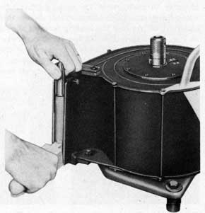
2. Cotter. Remove breech-bar securing-bolt spring pins, securing bolts, and cotter. See Fig. 11.
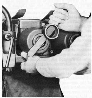
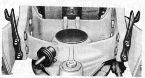
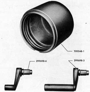
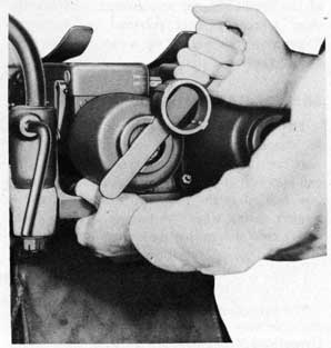
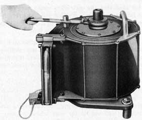
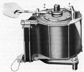
3. Breech-Casing Cap. Remove the breech-casing cap as shown in Fig. 12 by turning it off with the barrel seating ring spanner (2998143). The breech-casing cap retaining catch must be disengaged when the cap is first turned.
4. Breech Mass. Slide the breech mass to the rear and remove it from the breech casing. Any parts may be inspected or replaced as required.
5. Assembly. Reverse the above procedure to assemble the parts back into the gun. The gun may be returned to the uncocked position, or it may be run back into the cocked position after all parts are assembled.
STRIPPING
The stripping of the Gun Mounts Mk 24 and Mods is not a difficult job, but to prevent damage to the parts and injury to the personnel the stripping procedure should be followed in the order given below.
After the guns have been removed from the cradle, extreme care should be taken when unlocking the cradle at the five-degree or 30-degree elevation positions. The cradle springs and the weight of the cradle will cause the rear of the cradle to spring down violently. It is best to have one man hold up on the shoulder rests while a second man disengages the cradle lock.
For location of parts by part number, refer to Plate 2-Sectional Details of Gun Mount-at the end of this pamphlet. For converting Bureau of Ordnance part numbers to OE part numbers, in order to find parts stocked under OE numbers for older mounts, refer to Parts List or Numerical Index at the rear of this pamphlet, or to Cross Index List of Part Numbers on page 201 of OP 909 (March 1943 issue) or on page 215 of OP 911 (March 1943 issue). It should be noted that some parts do not have an OE part number, and are identified only by Bureau of Ordnance part numbers.
Operation Number
1. Sight. If a Sight Mk 4 and Mods is installed, remove it by loosening the three clamping screws with a sight wrench (367711-1).
The center screw must be backed out five or six turns and pushed to the left until the stop piece is disengaged from the notch in the breech casing. Slide the sight back toward the trigger cover and lift it off the gun. See Operation 6 for removal of Gun Sight Mk 14 Mods 2 or 6.
2. Magazine and Guns. Lock the guns and cradle in the five-degree elevation position; unship the magazines; trip the magazine catches down to free the interlock mechanisms; uncock the guns; unsnap the two trigger links; turn the trigger yoke to the rear and down; pull down the gun-securing-bolt withdrawing heads (299794-2) to disengage the securing bolts (299794-1) from the breech casing, and slide the guns to the rear and remove them from the cradle.
3. Cartridge Bag. Remove the cotter pins (12-Z-48-825) and flat washers (299957-6) from the cartridge-bag bolts (482546), and remove the bolts and cartridge bag and frame assembly (492491).
4. Cradle Springs. Elevate the cradle to the 85-degree position and lock there with the cradle lock. The cradle springs and the weight of the cradle will cause the rear of the cradle to spring down violently. Handle with care. Remove cradle spring housing nut cotter pins (367676-6), nuts (367701-2), and washers (367701-3), using wrench (299831-1). Remove the cradle spring and housing assemblies
29
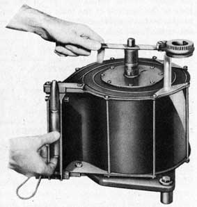
Figure 11. Barrel Springs and Breech Bars
Retained by Cocking Bar-Cotter and
Securing Bolts Removed from Gun.
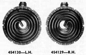
(454129-R.H. and 454130-L.H.) using cradle spring housing spanner (367543-1). These spring and housing assemblies are under load when engaged with the covers. Keep hands clear of the serrated edges. Note that the springs are heavier than those used on single mounts.
To strip the cradle spring and housing assemblies, remove the spring locating screws (299795-4) and lock washers (299797-3). Remove the springs (487478) from the housing assemblies (299798). The spring housing bushing (299796-2) is pressed in the housing and should not be removed unless it is desired to replace the bushing.
5. Weight Bands. Remove the weight-band pivot nuts (299800-3) and cotter pins (12-Z-48- 812). Remove the pivot bolts (299800-2) and weight band assemblies 99799-Fabric Band or 367776-1-Steel Band). Lower the cradle and lock it at the five-degree elevation position.
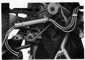
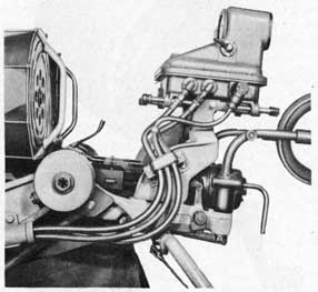
6. Sight. If a Gun Sight Mk 14 Mods 2 or 6 is installed, remove it according to the following procedure. Disconnect and cap or plug all hose connections. Disconnect the electrical cables. Remove the rubber manifold grommet (482544) from the manifold by pulling on the hoses and cable. Remove the hoses and gable from the manifold. Remove the power unit bracket from the adapters on the shields as an assembly with the power unit. Do not remove the power unit from the bracket unless necessary for further repair work on the power unit. Remove the sight unit from the sight bracket, with its slide rods, springs, and nuts. Do not remove the sight bracket from the cradle unless either the sight bracket or the cradle will be replaced. The
sight bracket has been boresighted to match the cradle and will have to be boresighted again if it is loosened or removed from the cradle. If the bracket must be removed, remove the four nuts (482523) and bolts (482501), and remove the bracket (492490).
Remove the hose manifold assembly (454144) from the carriage by removing the left lower rear shield bolt (299813-2), nut (299813-3) and lock washer (299932-3), and the manifold to carriage screw (482514).
7. Shields. Remove the four bolts (2998134) and nuts (299813-5) which hold the shield strap to the shields, and remove the strap (455387).
Remove the eight bolts (299813-2), nuts (299813-3), and lock washers (299932-3) which hold the shield brackets to the carriage, and remove the shield and bracket assemblies (367728-1-R.H. and 367728-2-L.H.) from the mount.
If complete stripping of the shields is required, remove the eight bolts (299813-6) and nuts (299813-5) which hold the shield brackets (367729-1-L.H. and 367729-2-R.H.) to the shield plates (375781-1-R.H. and 375781-2-
Figure 12. Tripping Cap-Retaining Catch and
Removing Breech-Casing Cap.
30
L.H.). If the shields are fitted with sight power-unit adapter plates, remove the adapter plate assemblies (454135-R.H. and 454136-L.H.) by removing the four nuts (299813-5) and two bolts (482543) which secure the two adapters to the shields and shield brackets. See Figs. 34, 36 and 38.
8. Shoulder Rests. Remove the two nuts (482524) and flat washers (299888-5) which retain the shoulder-rest brackets in the cradle. Remove the shoulder rests from the cradle, tapping the mount if necessary. Care must be taken to see that the shoulder-rest locating keys (482531) are not lost out of the shoulder-rest brackets when they are removed from the cradle.
For stripping procedure on the shoulder rest assemblies, see Chapter 4.
9. Handle Bars. Turn the cradle trigger yoke to the rear and downward, and remove the trigger idler-lever-to-link pin (482496) which is exposed from behind the pickup lever (482494). Remove the four screws (482518-front and 482519-rear) which hold the handle bar assemblies (492477-L.H. and 492478-R.H.) to the cradle. See Fig. 16.
For stripping procedure on the trigger mechanism on the left handle bar, see Chapter 4.
10. Cradle. Insert a pin punch in the hole in the bottom of the cradle for the rear stop-rod pin retaining pin (482527) and drive the pin up out of the cradle. Remove the rear stop-rod pin assembly (482472) from its hole in the cradle to disconnect the rear stop rod (454128) from the cradle. See Figs. 8 and 14.
Elevate the cradle to the 85-degree position and lock there with the cradle lock. Support the cradle and drive the two cradle trunnion pivot pins (299798-1), with their keys (299798-4), inward and remove the pins from the holes. Unlock the cradle lock and remove the cradle from the carriage. Do not remove the keys (29979K-4) from the trunnion pins, unless one of the pieces is to be replaced, as the keys are press-fitted into the pins. Attempts to remove them may result in damage to the parts.
If it is necessary to strip the cradle assembly, the following steps cover the operations for each unit.
Gun Securing Bolts. Remove the two pressure oilers (299932) from the gun-securing-bolt bosses. Drive out the gun-securing-bolt withdrawing-head pins (299794-5) and remove the withdrawing heads (299794-2). The gun-securing bolts (299794-1) and their springs (2997943) can now be removed. Drive the gun-securing bolt pins (299794-4) out of the securing bolts.
Trigger Mechanism. See Fig. 16. Remove the two pressure oilers (299932) from the trigger yoke and cradle. Remove the cotter pin (367676-2) from the trigger-yoke axis pin (482507) and slide the axis pin out of the yoke and cradle. Remove the snap ring (299665-4) and washer (482495) from the inner end of the trigger lever and yoke shaft assembly (482492), using pliers (299818-5) from the gun-tool roll, and slide the lever and shaft assembly out of the yoke and cradle and remove the trigger yoke assembly (454133) from the cradle. Remove the trigger idler lever (454132) from the shaft assembly. Do not attempt to strip the trigger lever and yoke shaft assembly (482492) into its component parts, trigger yoke-shaft lever (482494) and yoke shaft (482493). These parts are fitted together at a definite angle when manufactured and are serviced as an assembly. Push out the trigger link-pin retainers (482506) and remove the trigger link pins (482502) and the two trigger link assemblies (482503) from the trigger yoke (487482). Do not attempt to strip the trigger link assemblies, as they are serviced as an assembly.
Cheek Plates. Turn the cradle over and remove the sixteen cheek-plate screws (482515) and four cheek plates (487475). Remove the pressure oiler (299932) from the cam limit stop rod axis pin boss.
The cradle (492484-1) is now in a completely, stripped condition, unless it is fitted with a bracket for the Gun Sight Mk 14 Mods 2 or 6, which piece should not be removed, as pointed out under Operation 6.
11. Pivot Retainer. See Fig. 13. Unscrew and remove the pivot-retainer lock-screw cover plug (299969-3) from the base of the carriage. Unlock the carriage lock and turn the carriage until the pivot-retainer lock screw is exposed by the hole in the carriage. The position of the lock screw is indicated by an arrow on the stand
31
below the carriage. Unscrew the lock screw (299962-2) and remove it from the carriage. Lock the carriage lock by lifting up on the lock lever and turning the carriage until the lock plunger snaps into a hole in the pivot retainer. Turn the carriage counter-clockwise, as viewed from above, until the pivot retainer is unscrewed from its mating threads in the pivot housing. About 13 turns are required completely to disengage the threads.
12. Carriage. Remove the rubber pivot cover (299946-2), and remove the eight carriage-to-pivot screws (299946-1). Turn the carriage so that the cam limit stop lever (492474) is at a low point in the cam plates, and lift off the carriage. Note. If the cams have never been profiled and are still in the blank form, it is necessary to remove one of them to get the carriage off. If it is necessary to tap the bottom of the carriage to break it loose from the pivot, replace two of the carriage-to-pivot screws and thread them into the pivot several turns, to prevent the carriage from falling off the stand.
If it is necessary to strip the carriage assembly, the following steps cover the operations for each unit.
Cocking Bars. Push the cocking-bar pivot-pin washer (482500) into the counterbore in the carriage until the pivot-pin retaining pin (482498) can be removed from the pivot pin. Remove each retaining pin, and remove the cocking bars (455385-R.H. and 455386-L.H.) and pivot pins (482497). Remove the washers and the pivot-pin springs (482499) from the carriage. Remove the cocking-bar clips (454138) by removing the two screws (482533) which hold each clip to the carriage.
Cradle Lock. Remove the oiler (299932), detent ball spring (299968-2), and detent ball (299966-3) from the bottom of the carriage arm at the cradle lock. Remove the rubber lock lever seal (299968-3), the two screws (482517) which hold the lock lever housing to the carriage, and the lock lever housing assembly (482489). Drive the lever axis pin (299966-4) out of the lock lever housing (487480) and remove the lock lever (299966-2), the two lever spacers (299969-2) and the lock plunger (299943-5).
Carriage Lock. See Fig. 13. Remove the
pressure oiler (299932), the detent-ball spring (299968-2), and the detent ball (299966-3) from the carriage, below the lock lever. Remove the rubber lock-lever seal (299968-3) and the set screw (482491) which holds the lock-lever housing to the carriage; and remove the lock-lever housing assembly (482490). The carriage lock plunger (299966-1) can now be pulled out of its hole in the carriage, from the bottom side of the carriage. Do not remove the lock-lever hole plug (299966-5) from the carriage unless it is desired to replace the plug. Drive the lever axis pin (299966-4) out of the carriage lock-lever housing (454131) and remove the lock lever (299966-2) and the two lever spacers (299969-2).
Cradle Spring-Housing Covers. Remove the four screws (299788-7) and lock washers (299791-9) which hold the cradle spring-housing covers (299788-2) to the carriage and remove the covers. Remove the pressure oilers (299932) from the outside of each trunnion arm just forward of the spring-housing covers.
Cam Shield. Remove the cam shield (481477) by removing the three screws (482517) which hold the shield to the carriage. See Fig. 13.
Cam Limit Stop Parts. See Fig. 14. Remove the retainer screw (482516) and pin retainer (482486) from the idler lever. It will be noted that on some gun mounts the several pin retainers are secured by a plain screw and a lock washer instead of by the self-locking screw (482516). Remove the two pin assemblies (482475) from the idler lever, with the rear stop rod (454128). The pin assemblies are made of axis pin (482476) and pressure oiler (299932). If the cams have been machined to control the guns on a particular vessel, do not disassemble or loosen the front stop rod (454127) or clevis lock nut (482522) from the stop-rod clevis (454125) unless one of the pieces is to be replaced. If it is necessary to separate these parts, loosen the clevis lock nut (482522) and screw the front stop rod (454127) out of the clevis. Take care not to lose the stop-rod ball out of the rod. After the rod has been removed, turn the stop-rod ball (482480) sideways in its socket and remove it. Do not remove the ball-retainer groove pin (482525) from the rod. Remove the retainer screw
32
(482516) and bolt retainer (482483) from the stop-rod clevis and remove the pin assembly (482475) and stop-rod clevis (454125). Turn the stop-rod ball (482480) sideways in its socket and remove it. Remove the retainer screw (482516) and bolt retainer (482483) from the stop-rod lever. Remove the roller shaft assembly (482481) and roller (482484). The shaft assembly is composed of a shaft (482482) and an oiler (299932). Remove the lever screw (482520) and washer (482485), and remove the cam stop lever (492474) from the carriage. Do not remove the ball-retainer groove pin (482525) from the lever. Remove the pressure oiler (299932) from the lever boss on the front of the carriage. Turn the carriage upside down; drive out the idler-lever axis-bolt retainer pin (482528); remove the idler-lever bolt assembly (482477) and remove the stop-rod idler lever (487476). The bolt assembly is composed of a bolt (482478) and a pressure oiler (299932).
Carriage Packing. Do not remove the carriage packing or packing retainer if it is not necessary to do so. If the carriage packing (299966-6) is damaged, it should be removed by pulling it out of its retainer. If the packing retainer (487481) is damaged, the retainer and packing must both be removed. This leaves the carriage (492480-1) in a stripped condition.
13. Pivot Retainer. Remove the pivot retainer (299963-1) from the top of the stand, and then remove the pivot thrust upper bearings (299962-3).
14. Pivot. Screw a pair of ring bolts or other screws in the top of the pivot
and lift the pivot (365905-1) out of the pivot housing. If necessary for replacement or cleaning, remove the pressure oiler (299932) from the top of the pivot.
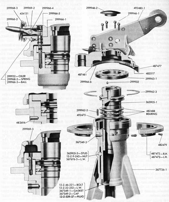
15. Pivot Housing. Remove the pivot thrust lower bearing, whether plain bearing or ball bearing type (299962-3-plain bearing or 482488-ball bearing), from the pivot housing. Remove the cam plates (487472-R.H. and 487473-L.H.) by removing the eight screws (482479) which hold the cam plates to the pivot housing. Each blank is dowelled to the pivot housing with a dowel (482616) which is pressed into a hole in the pivot housing. It may be necessary to pry slightly on the cam blanks to loosen them from the dowels. Remove the draw-stud nut (12-Z-9-245) and lock washer (3676765) and remove the draw stud (365905-3) from the stand. Remove the two dowel screws (367549-3) which lock the pivot housing (492498-plain bearing or 492475-ball bearing) in the stand weldment and remove the pivot housing. Remove the pipe plug (12-Z329-57) from the pivot housing cap. Remove the six screws (12-Z-46-221) and lock washers (12-Z-22-252) which hold the pivot-housing cap (367549-2) and gasket (367549-1) on the bottom of the housing, and remove the pressure oiler (299932) from the shoulder on the housing. The cam dowels (482616) can not be removed from the pivot housing without damaging them.
16. Stand Weldment. Remove the pressure oiler (299932) from the sleeve of the weldment, leaving the stand weldment (367726-1) in a stripped condition.
ASSEMBLY
These instructions for assembling the Gun Mounts Mk 24 and Mods cover the complete assembly, starting with all serviceable units completely stripped. The instructions should be followed in the order given, to facilitate the operation and to prevent damage to the parts or injury to the personnel. Assembly procedure for the handle-bar trigger parts is covered in Chapter 4.
Care must be exercised to see that all dirt,
moisture, or foreign matter is removed from the parts as they are installed, and particularly from machined surfaces.
For location of parts by part number, refer to Plate 2-Sectional Details of Gun Mount-at the end of this pamphlet. For converting Bureau of Ordnance part numbers to OE part numbers, in order to find parts stocked under OE numbers for older mounts, refer to Parts List or Numerical Index at the rear of this
33
pamphlet, or to Cross Index List of Part Numbers on page 201 of OP 909 (March 1943 issue) or on page 215 of OP 911 (March 1943 issue). It should be noted that some parts do not have an OE part number, and are identified only by Bureau of Ordnance part numbers.
Adjustment of the pivot retainer, and consequent pivot thrust bearing adjustment, is of extreme importance to assure smooth, easy training of the gun mount. This is covered under Operation 4 for both plain-type thrust bearing and ball-type thrust bearing gun mounts.
Operation Number
1. Pivot Housing. See Fig. 13. Assemble the pivot-housing cap (367549-2) and gasket (367549-1) on the pivot housing (492498-plain bearing type or 492475-ball bearing type) with six screws (12-Z-46-221) and lock washers (12- Z-22-252). Coat the interior of the stand weldment (367726-1) and the exterior of the pivot housing with bearing grease OS-1350, and place the pivot housing in the weldment with the draw stud notches of the two pieces in alignment. Install and stake in place the two dowel screws (367549-3) holding the housing in the weldment. Coat the draw stud (365905-3) with grease OS-1350 and install it in the stand and secure with lock washer (367676-5) and nut (12-Z-9-245). Do not tighten the nut excessively as the pivot housing may be distorted. If the cam dowels (482616) were removed, drive a pair of dowels into the reamed holes in the pivot housing. Assemble the cam plates (487472R.H. and 487473-L.H.) on the pivot housing over the cam dowels and secure with eight screws (482479). Note. If the cams have never been machined and are still in the blank form, leave one of them off in order to have clearance to install the carriage in a later operation. Install a pressure oiler (299932) in the stand sleeve and in the pivot housing. The male threads should be coated with white lead or other sealer.
2. Pivot Thrust Lower Bearing. Clean the inside of the pivot housing and coat with bearing grease OS-1350. The lower thrust bearing is a ball bearing in Stands Mk 7 Mods 21, 22,
653659 O-45-5
and 23. It is a babbitt-faced steel bearing in Stands Mk 7 Mods 12, 13, and 14. See page 21 for further description.
If Ball Bearing. Wash the ball bearing (482488) in clean kerosene, oleum spirits, or No. 1 fuel oil in a clean container; dry the bearing and immediately pack it with bearing grease OS-1350. Place the bearing in the seat of the pivot housing. Either race may be up, as they are interchangeable.
If Babbitt Bearing. Clean and coat two thrust bearing halves (299962-3) with bearing grease OS-1350, and place them in the bearing seat of the pivot housing with the babbitted sides up and their locating lugs entered into the locating notches in the pivot housing.
3. Pivot and Pivot Upper Thrust Bearing. Clean the pivot (365905-1); coat it with grease OS-1350; and place it in the pivot housing. Grease the pivot thrust upper bearing halves (299962-3) with grease OS-1350 and place them in the pivot housing with the babbitted sides down and their locating lugs in the locating notches. Install the pivot-housing-cap pipe plug (12-Z-329-57) in the pivot housing cap. The thread of the pipe plug should be coated with white lead or other sealer.
4. Pivot Retainer. Place the pivot retainer (299963-1), with its flat 6 1/2-inch diameter bearing surface down, in the pivot housing and screw it into its mating threads as far as it will go, using a 1/2-inch dowel in one of the holes as a driver. The force required to turn the pivot increases when the retainer is screwed down tight. Check the pivot turning effort to make certain that the retainer is tight, and then back the retainer out at least one hole, but not more than two holes, until one of the holes is in line with the indicating arrow on the outside of the stand which shows the location of the lock-screw hole in the pivot housing. Install the lock screw (299962-2) and tighten it securely. Screw a pressure oiler (299932) into the tapped hole in the top of the pivot. The male thread should be coated with white lead or other sealer.
5. Carriage. Place the stop-rod idler lever (487476), with its tapped hole for the bolt-retainer plate facing out, in line with the
34
Figure 13. Exploded Cut-Away View of Gun Mount Mk 24 Mod 5.
35
reamed hole on the left side of the carriage (492480-1), and insert the idler-lever bolt assembly (482477) through the two pieces until the groove-pin hole in the carriage lines up with the hole in the shaft assembly, and drive in the idler-lever axis-bolt retainer pin (482528). The idler-lever bolt assembly consists of a bolt (482478) and a pressure oiler (299-932). Turn the carriage over and install the packing retainer (487481) and stake it in place. Paint the inside of the retainer with shellac and fit the packing (299966-6) into the retainer and smooth it out into the retainer uniformly all the way around. Attach the cam shield (487477) to the carriage with three screws (482517). Assemble the cam stop lever (492474) on the carriage and secure with lever screw (482520) and washer (482485). Install lock-plunger hole plug (299966-5) in the top of the plunger hole, with the hollow side of the plug down. Strike the center of the plug with a hammer and drift until a dimple is formed and the plug secured in the hole. Assemble the carriage lock lever (299966-2) and two lever spacers (299969-2) into carriage lock-lever housing (454131) and secure by driving in lever axis pin (299966-4). Stake the pin in place at both ends. Dip the carriage lock plunger (299966-1) in light preservative oil OS-1362 and slide it into its hole from the bottom of the carriage, with the grooved end of the plunger entering into the hole first. Enter the carriage lock-lever housing assembly (482490) into its hole in the carriage and engage the end of the lever with the notch in the end of the lock plunger. Secure the housing assembly in the carriage by installing and tightening set screw (482491) in the carriage.
Saturate the carriage packing (299966-6) with light preservative oil OS-1362, and place the carriage on the pivot and secure it with eight carriage-to-pivot screws (299946-1). These screws should be tightened to 75 foot-pounds torque, using a torque wrench (2999912) and male socket (299992-2). If the torque wrench is not available, tighten with a pull of 75 pounds on a wrench handle one foot long or 38 pounds on a handle two feet long.
If one of the cam blanks (487472-R.H. or 487473-L.H.) was left off the stand while performing Operation 1, install it and secure with four screws (482479).
Cradle Lock. Assemble the cradle lock plunger (299943-5), the cradle lock lever (299966-2) and two lever spacers (299969-2) into the cradle lock-lever housing (487480) and secure by driving in lever axis pin (299966-4). Stake the pin in place at both ends. Oil the plunger and axis pin with light preservative oil OS-1362 and assemble this cradle lock-lever housing assembly (482489) on the carriage, fastening it with two screws (482517). Place a detent ball (299966-3) and detent-ball spring (299968-2) in the oil hole in the bottom of the carriage arm under the cradle lock and secure by screwing in a pressure oiler (299932). The male thread should be coated with white lead or other sealer.
Carriage Lock. Place a detent ball (2999663) and detent-ball spring (299968-2) in the oil hole under the carriage lock lever and secure by screwing in a pressure oiler (299932). The male thread should be coated with white lead or other sealer.
Cradle-Spring Housing Covers. Screw a pair of pressure oilers (299932) into the cradle trunnion-pin oil holes on each carriage arm. The male threads should be coated with white lead or other sealer. Assemble the two cradle-spring housing covers (299788-2) on the carriage and secure each one with four screws (299788-7) and lock washers (299791-9).
Cam Limit Stop Parts. See Fig. 14. If the ball-retainer groove pin (482525) is not in the hole in the end of the cam limit stop lever (492474), drive a new one into the hole in the end of the cam stop lever until its outer end is flush with the lever and the inner end protrudes 3/16 inch into the ball socket. Place a stop-rod ball (482480) in the socket so that its locating hole is engaged with the retainer pin, and turn the ball sideways so that its main hole is exposed. Align the stop-rod clevis (454125.) with the lever ball and insert a stop-rod pin assembly (482475), securing the pin assembly with a pin retainer (482483) and retainer screw (482516). It will be noted that on some gun mounts the several pin retainers are secured by a plain screw and a lock washer instead of by the self-locking screw (482516). The clevis should be positioned with the retainer on the lower side to keep water from entering into the lubrication
36
Figure 14. Exploded View of Cam Limit Stop Mechanism.
fitting. (These parts are shown with the retainer on top in Fig: 14 only to make the picture clearer.) The stop-rod pin assembly is made of a stop-rod pin (482476) and an oiler (299932). If the ball-retainer groove pin (482525) is not in the hole in the end of the front stop rod (454127), drive a new one in until it is flush with the rod and the inner end protrudes 3/16 inch into the ball socket. Thread the clevis lock nut (482522) onto the front stop rod and screw the stop rod into the clevis. Place a stop-rod ball (482480) in the socket so that its locating hole is engaged with the retainer pin, and turn the ball sideways so that its main hole is exposed. Attach the front stop-rod assembly (482487) to the stop-rod idler lever, and also attach one end of the rear stop rod (454128) to the idler lever, using a pair of stop-rod pin assemblies (482475). These assemblies consist of a stop-rod pin (482476) and a pressure oiler (299932). Secure the pin assemblies with the pin retainer (482486) and a retainer screw (482516) threaded into the idler lever. Screw a pressure oiler (299932) into the tapped hole on the cam stop lever boss on the front of the carriage. Coat the thread of the oiler with white lead or other sealer.
Cocking Bars. Assemble the cocking bar clips (454138) on the carriage with four screws (482533). See Fig. 15 for their correct position. Assemble the cocking bars (455385-R.H. and 455386-L.H.) on the carriage with the pivot pins (482497). Place a cocking-bar pivot-pin spring (482499) and washer (482500) on each pivot pin, with the hollow side of the washer toward the end of the pivot pin. Compress the spring by forcing the washer into the counterbore of the carriage arm and insert a pivot-pin retaining pin (482498) in the hole of each pivot pin, and allow the washer to snap back and secure the retaining pin.
6. Cradle. Coat the gun-securing-bolt holes in the cradle (492484-4) with bearing grease OS-1350. Drive the gun-securing-bolt pins (299794-4) into the gun-securing bolts (2997941) until they protrude equally on both sides. Place the gun-securing-bolt springs (299794-3) over the securing bolts and slide the bolts into their holes in the cradle. Drive the securing-bolt withdrawing heads (299794-2) onto the bolts and fasten them by driving in the withdrawing-head pins (299794-5). Stake the ends of each pin slightly. Coat the threads of two
Figure 15. Correct Installation of
Cocking Bar Clips.
38
pressure oilers (299932) with white lead or other sealer and assemble them into the securing-bolt bosses on the bottom of the cradle.
Assemble the four cheek plates (487475) on the cradle with sixteen screws (482515). The end of each plate having an extension on it goes to the front. Coat the thread of an oiler (299932) with white lead or other sealer and screw it into the oil hole on the bottom of the cradle at the cam limit stop rear rod pin hole aft of the left trunnion pin hole.
Trunnion Pins. Drive the trunnion-pin keys (299798-4) into the keyways of the two cradle trunnion pivot pins (299798-1). Coat the pins and the pin holes of the carriage and cradle with bearing grease OS-1350; align the cradle and carriage; and drive the trunnion pins through the cradle and carriage holes. Locking the cradle in the 85-degree elevation position with the cradle lock while driving in the trunnion pins will help to align the cradle. When finished, lock the cradle in the five-degree elevation position with the cradle lock.
Cradle Trigger Linkage. See Fig. 16. Make a trigger-yoke assembly (454133) by assembling two trigger-link assemblies (482503) on a trigger yoke (487482), fastening them with a pair of trigger link pins (482502) and link-pin retainers (482506), and screwing a pressure oiler (299932) into the tapped hole in the yoke, after coating the oiler thread with white lead or other sealer. Assemble the yoke assembly on the cradle by securing its right end with a trigger-yoke axis pin (482507) and cotter pin (367676-2). Place the trigger idler lever (454132), with its flat contact side forward, on the trigger lever and yoke shaft assembly (482492) and pass the lever and yoke shaft assembly through the cradle and yoke assembly. The lever and yoke shaft assembly is furnished as a unit assembly. Its component parts are not furnished as spare parts. The yoke assembly should be in an erect position when the square end on the yoke shaft is entered into the yoke assembly, with the trigger lever pointing down. Secure the yoke shaft at its inner end with a flat washer (482495) and a snap ring (299665-4), using the pliers (299818-5) from the gun-tool roll. Coat the thread of a pressure oiler (299932) with white lead or other sealer
and screw it into the yoke shaft oil hole on the cradle.
7. Handle Bars. For assembly instructions for the trigger mechanism on the left handle bar, see Chapter 4.
Assemble the two handle bar assemblies (492477-L.H. and 492478-R.H.) to the cradle with four screws (482518-front and 482519- rear). Turn the cradle-trigger yoke to the rear and downward; align the handle-bar trigger to idler-lever link (482537) with the trigger idler lever (454132) on the cradle and fasten the two pieces together with an idler-lever-to-link pin (482496). Return the trigger yoke to its erect position and the idler-lever-to-link pin is prevented from coming out of its hole by the trigger lever on the yoke shaft.
8. Shoulder Rests. For assembly instructions for shoulder rests, see Chapter 4.
Place a shoulder-rest locating key (482531) in each shoulder-rest bracket and assemble the two shoulder rest and bracket assemblies (492488-R.H. and 492489-L.H.) to the cradle, fastening them with a flat washer (299888-5) and a nut (482524) at each shoulder-rest bracket.
9. Shields. Fasten the shield brackets (367729-1-L.H. and 367729-2-R.H.) to the carriage with eight bolts (299813-2), nuts (299813-3), and lock washers (299932-3). The bolt heads are to be on the inside of the carriage arms as shown in Fig. 15. Fasten the shield plates (375781-1-R.H. and 375781-2-L.H.) to the shield brackets with eight bolts (299813-6) and nuts (299813-5). The bolt heads should be on the front side of the shield plates. The shield plates must be installed with their hardened faces to the front. These faces are so marked and, also, the lower inner corner of the left hand shield is cut off diagonally. Fasten the shield strap (455387) on the back side of the shields, with its hump up, with four bolts (299813-4) and nuts (299813-5). The bolt heads should be on the front side of the shields.
See Chapter 5 for installation of the power-unit adapter plates, sight bracket, and hose and cable manifold of the Sight Adapter Equipment Mk 2 Mod 0 for the Gun Sight Mk 14 Mods 2 or 6.
39
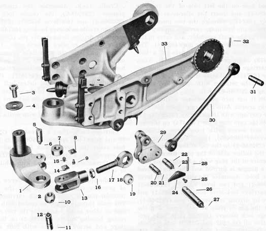
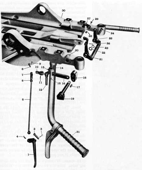
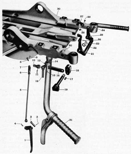
Figure 16. Exploded View of Trigger Mechanism
1. 454140
Trigger.
2. 482539
Pin-trigger axis.
3. 12-Z-48-821
Pin-cotter.
4. 482538
Pin-trigger to rod.
5. 454139
Rod-trigger.
6. 482521
Nut-clevis lock.
7. 482509
Clevis-trigger rod.
8. 482530
Pin-clevis.
9. 12-Z-48-811
Pin-cotter.
10. 454137
Lever-trigger intermediate.
11. 482525
Pin-groove.
12. 482534
Lever Assembly-trigger.
13. 299932
Oiler-pressure.
14. 482530
Pin-clevis.
15. 12-Z-48-811
Pin-cotter.
16. 482537
Link-trigger to idler lever.
17. 482496
Pin-trigger idler lever to link.
18. 454132
Lever-trigger idler.
19. 482492
Lever and Shaft Assy- idler and yoke.
20. 299932
Oiler-pressure.
21. 487482
Yoke-trigger.
22. 482495
Washer-yoke shaft.
23. 299665-4
Ring-yoke shaft snap.
24. 482507
Pin-trigger yoke axis.
25. 299932
Oiler-pressure.
26. 367676-2
Pin-cotter.
27. 482503
Link Assembly-trigger.
28. 482502
Pin-trigger link.
29. 482506
Retainer-trigger link pin.
30. 492484-1
Cradle.
31. 492479
Bar-handle-L.H.
40
10. Weight Bands. Elevate the cradle and lock it in the 85-degree position. Assemble the two weight band assemblies (299799-Fabric Band or 367776-1-Steel Band) to the cheek plates with the pivot bolts (299800-2), nuts (299800-3), and cotter pins (12-Z-48-812). The short end of each band at the weight end is to be on the stand side of the weight, to keep from hooking on cases in a full cartridge bag. Depress the cradle and lock it in the five-degree elevation position.
11. Cartridge Bag. Fasten the cartridge bag and frame assembly (492491) to the carriage and cradle with a pair of cartridge-bag bolts (482546). Each bolt is retained by a pair of washers (299957-6) and cotter pins (12-Z-48- 825).
12. Cradle Springs. Press a cradle-spring housing bushing (299796-2) into each of the cradle-spring housing assemblies (299798). Place a cradle spring (487478) in each housing as shown in Fig. 17 and secure the springs by assembling the spring-locating screws (2997954) and lock washers (299797-3). Note that these springs are heavier than those used on single mounts.
Elevate the cradle and lock it at the 85-degree position. Place the right-hand spring and housing assembly (454129) over the right hand trunnion pin and secure it loosely with, the trunnion-pin washer (367701-3) and nut (367701-2). Place a cradle-spring housing spanner (367543-1) over the top of the spring housing and engage it with the spring-locating screw. Turn the spring housing in a counter-clockwise direction (as viewed from the right
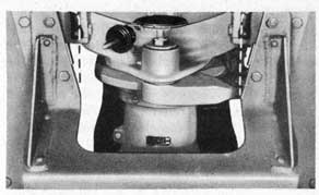
Figure 17. Cradle Spring and Housing Assemblies.
side of the gun mount) until tension is felt, and then turn it in the same direction one full notch further and engage the spring housing with the spring-housing cover in the first notch that will engage. Tighten the trunnion pin nut, using wrench (299831-1), and secure it with a cotter pin (367676-6).
Place the left-hand spring and housing assembly (454130) over the left-hand trunnion pin and secure it loosely with the trunnion-pin washer (367701-3) and nut (367701-2). Place a cradle-spring housing spanner (367543-1) over the top of the spring housing and engage it with the spring-locating screw. Turn the spring housing in a clockwise direction (as viewed from the left side of the gun mount) until tension is felt, and then turn it in the same direction one full notch further and engage the spring housing with the spring-housing cover in the first notch that will engage. Tighten the trunnion-pin nut and secure it with a cotter pin (367676-6).
Note. The installation of a Gun Sight Mk 14 Mods 2 or 6, or changing from ribbed barrels to solid barrels, may require adjustment of the cradle-spring cases one or two notches in either direction to improve the balance of the guns.
Unlock the cradle lock; depress the cradle to the five-degree elevation position; and lock there with the cradle lock. Handle with care. The cradle springs and the weight of the cradle will cause the rear of the cradle to spring down violently if not properly handled.
13. Guns. Withdraw and lock the gun-securing bolts. Ship the two guns (20-mm Mechanisms Mk 4 Mod 1) in the cradle and secure by unlocking the gun-securing bolts and allowing them to snap up into the breech-casing holes.
Note. The barrel-spring casing on the right-hand gun must be turned over, as covered in Chapter 6 and shown in Fig. 18, to get its cocking stud on the outside of the gun. Turn the cradle trigger yoke upward and forward and snap the two trigger links (482503) over the breech-casing triggers.
14. Handle-Bar Trigger-Rod Adjustment. The length of the handle-bar rod (454139) and its clevis (482509) should be adjusted so that the handle-bar trigger (454140) will just touch a 1/4-inch spacer placed between the trigger and
41
the handle bar grip, when the trigger is squeezed as close to the handle bar grip as the travel of the breach casing triggers (299698-6) will allow. Tighten the clevis check nut (482521) after the adjustment has been made.
15. Cam Limit Stop Clevis Adjustment. This procedure is to be followed if the cam plates have never been machined and are still in the blank form. If the cam plates have been profiled to control the guns on a particular vessel, follow the procedure outlined under MAINTENANCE on page 51.
Note. After this operation is completed, the cam limit stop will not allow the cradle to be depressed from the 85-degree elevation position.
a. Remove the guns from the mount.
b. Unlock the cradle and elevate and lock it in the 85-degree position. Handle with care. The cradle springs and the weight of the cradle will cause the rear of the cradle to spring down violently if not properly handled.
c. Assemble the cam limit stop roller (482484), the roller shaft assembly (482481), which is composed of a shaft (482482) and an oiler (299932), the shaft retainer (482483), and a retainer screw (482516) in the cam limit stop lever. See Fig. 14.
d. Remove the front stop-rod-to-idler-lever pin assembly (482475).
e. Line up the rear end of the rear stop rod (454128) with its axis-pin hole in the cradle and insert the rear stop rod pin assembly (482472) through the two pieces until the groove-pin hole in the cradle lines up with the groove-pin hole in the pin assembly and drive in the stop-rod-pin retainer pin (482527). The stop rod pin assembly consists of a pin (482473) and a threaded plug (482474), permanently fastened together.
f. The length of the front stop rod (454127) and the stop-rod clevis (454125) should be adjusted, by screwing the rod in or out of the clevis, so that when the front stop-rod-to-idler-lever pin assembly (482475) is replaced, the cam roller will be firmly bearing on, or with not more than 0.02 inches clearance from the cam blanks, with the cradle locked in the 85-degree elevation position.
653659 O-45-6
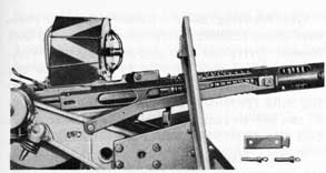
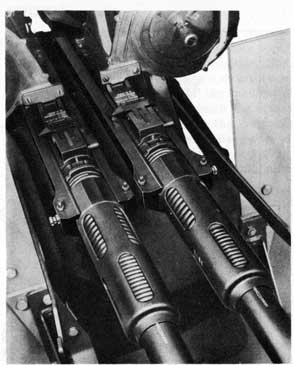
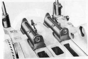
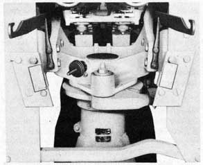
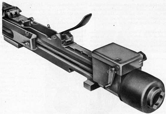
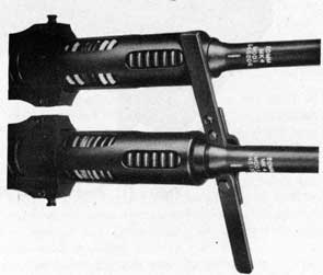
Figure 18. Two Guns Mounted on Cradle.
g. Tighten the clevis lock nut (482522).
h. In no instance should the adjustment be so tight as to interfere with locking the cradle at 85 degrees elevation.
16. Lock-Lever Seals. Install the rubber lock-lever seals (299968-3) on the lock levers and housings at the cradle and carriage locks.
17. Painting. Paint all new parts and touch up all chipped or scratched painted surfaces with gray paint in accordance with specification OS-52, treatment No. 2, ocean gray color.
18. Lubrication. Grease all bearings fitted with pressure oilers (299932) with bearing grease OS-1350, using grease gun (299832-1). There are 19 oilers on the gun mount. Coat the cam roller and the edges of the cams with bearing grease OS-1350.
Coat all unpainted metal surfaces with rust preventive compound NDS 52-C-18 grade 1.
19. Pivot Cover. Install the rubber pivot cover (299946-2) on the top of the pivot.
42
Figure 19. Working Circle for 20-mm Gun Mounts Mk 24 Mods 2 and 5.
43
INSTALLATION
GENERAL INSTALLATION DATA
The installation of the Gun Mounts Mk 24 and Mods differs from that of other mounts in several respects. The guns have a rate of fire twice that of a single gun; so, if space allows, it is suggested that two ammunition ready lockers be installed per gun mount instead of one. The magazines for the two guns are not the same, the right gun using Magazines Mk 4 Mod 0 (right hand) and the left gun using Magazines Mk 5 Mod 0 (left hand). If two ready lockers are used, it is recommended that each ready locker be filled with only one type of magazine to prevent confusing the ammunition handlers and, further, that the ready locker for the Magazines Mk 5 Mod 0 be marked with the same identifying gray zig zag as the magazines.
The gun mount must be firmly secured to the deck, as the shock of the cam limit stop stopping the guns in train will shift the gun mount unless it is bolted down tightly. If the gun mount is mounted on a foundation which is welded to the deck, it is recommended that the foundation be kept as low as possible unless a gunner's platform is used. If a gunner's platform is used, the height of the gun foundation above the platform should be kept to a minimum. In general, foundations of excessive height seriously limit the minimum elevation to which the gun layer can depress the guns.
The bolt holes in the deck or foundation should be laid out as shown on Fig. 19, with one of the holes pointing directly forward from the center of the mount. Inspection of the gun mount will show that there is only one bolt hole in the base ring which is adjacent to a foot cleat. The gun mount should be placed on the deck with this bolt hole lined up with the forward hole in the deck. With the mount so installed, the pivot-housing draw stud will also be on the forward side of the mount. This method of orientation of the mount is in accordance with the Working Circle Drawing.
PREPARATION OF CAM LIMIT STOP
The limit stop on this mount is a train and depression cam limit stop, incorporated as an
integral part of the gun mount. The purpose of the stop is to prevent the guns from being trained or depressed into any position that would permit firing into the ship's structure or equipment. This restriction of the movement of the guns is accomplished through the action of a roller follower, mounted on the carriage, engaging a disc cam mounted on a fixed part of the stand. The roller follower is connected by a linkage to the cradle, to limit the minimum depression of the cradle.
The profile of the cam is determined by the degree of restricted movement of the guns, and since the degree of restriction will vary for each gun location, it is necessary to lay out the cam after the mount has been installed aboard the ship.
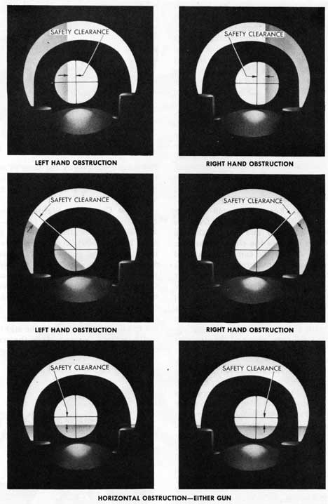
Safety Limits. The Bureau of Ordnance instructions for determining the limits for plot. ting stop cams are set forth in NAVORD OCL G8-43 of 7 April 1943. Pertinent material from this letter, with reference to the subject gun mount, is quoted as follows:
"6. The policy of the Bureau of Ordnance in regard to train and elevation limit stops in general, whether of the pipe rail type or the cam type, and as applied to all gun mounts and turrets, regardless of caliber, is outlined as follows:
(a) The function of these stops is to prevent movement of the gun into a position where its fire would endanger:
(1) any part of the fixed structure of the ship (such as a deck house); or
(2) adjacent moveable equipment (such as a crane or a gun mount) with the latter in its position of least interference.
(b) In considering interferences caused by other moveable equipment, it is obvious that valuable arcs of fire would be lost if the limit stops were set to exclude all possible interferences. Therefore, in general, a limit stop is intended to prevent an interference that cannot be avoided otherwise.
44
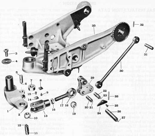
Figure 20. Exploded View of Cam Limit Stop Mechanism.
(c) Limit stops are not intended to protect adjacent personnel from blast. An exception to this rule may exist if the adjacent personnel (a director crew, for example) are necessary for the service of the gun. Generally speaking, exposed persons will have to leave their stations if a near-by gun trains into a position where they would be injured by blast.
(d) The adjustment or machining of limit stops, which will determine the effective limiting angles, is the responsibility of the ship's force. As a general rule, a stop should be set so that with the gun in its limiting position, the axis of the bore of the gun will clear the interfering object by at least one caliber (for guns of 5" bore and larger), or by at least five inches (for guns smaller than 5")."
A fixed safety clearance of five inches for 20-mm guns imposes objectionable limitations on the heights of splinter bulwarks in many instances, and, at the usual range of these bulwarks, five inches is considered excessive for a minimum clearance. Conversely, at maximum existent ranges on some vessels, five inches is considered inadequate. Therefore, in laying out the cam profiles for the 20-mm Gun Mounts Mk 24 and Mods, the minimum safety clearance shall be an angular allowance of 10 mils, except that at no range shall the clearance be less than two inches. The 10-mil angle subtends two inches of clearance at a range of approximately 17 feet, under which the two-inch clearance becomes applicable. It is emphasized that these clearances are all minimum values and that larger clearances are sometimes advisable. Optimum determination of a specific clearance depends on the conditions surrounding the particular gun, so an installation that has a minimum of restricted area and yet provides adequate safety for all contingencies will be the result of exercising careful judgment in determining necessary safety clearances.
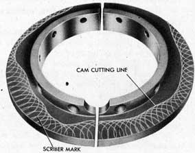
Laying Out Cams. The gun mount is shipped to the installing activity with the cam blanks (487472-R.H. and 487473-L.H.) bolted and dowelled in place on the stand. The cam limit
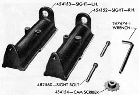
Figure 21. Tools for Scribing Cams.
stop will not allow the cradle to be depressed from the 85-degree elevation position. Secure the mount to the foundation, as shown in Fig. 19, and proceed with the following operations. See Fig. 20 for part numbers and nomenclature of the limit-stop' mechanism. See Fig. 21 for tools used in laying out the cam blanks. The general arrangement of the parts is shown in Figs. 22 and 23.
Operation Number
1. Cradle Springs. Loosen both of the cradle-spring housing nuts (367701-2) and slide the cradle-spring housing assemblies (299798) out on the trunnion pins until they are out of engagement with the spring-housing covers. Do this carefully, keeping hands clear of the toothed edges, as the housings are under spring tension and will tend to rotate on becoming disengaged. The cradle-spring housing spanner (367543-1), located in the mount tool bag, will facilitate this operation by providing the necessary leverage against the spring tension.
2. Cradle Lock. If the cradle lock is not locked, to hold the cradle in the 85-degree elevation position, lock it by pulling the lock lever outwards.
3. Clevis Adjustment. With the cradle lucked in the 85-degree elevation position, the cam roller should be firmly bearing on, or with not more than 0.02 inch clearance from the cam blanks. If the clearance between the roller and the cam. blanks is in excess of the above tolerance, then it is necessary to adjust the length of the clevis (454125) on the front rod (454127).
46
Figure 22. Cam Limit Stop Parts Mounted on Carriage.
Figure 23. Cam Limit Stop Parts Mounted on Carriage.
47
Do this by loosening the clevis lock nut (482522), removing the pin retainer (482486) with its screw (482516) from the idler lever, and removing the stop-rod pin (482476). It will be noted that on some gun mounts the several retainers are secured by a plain screw and lock washer instead of by the self-locking screw (482516). Turn the front rod in the clevis one half turn at a time until the stop-rod pin can be inserted through the front stop rod and idler lever (487476) and still have correct roller-to -cam-blank adjustment. When correct adjustment is obtained, secure by assembling the pin retainer and retainer screw and tightening the lock nut. Recheck the roller-to-cam-blank adjustment after the lock nut has been tightened. In no instance should the adjustment be so tight as to interfere with locking the cradle at 85 degrees elevation.
4. Cam Scriber. Remove the pin retainer (482483) and retainer screw (482516) from the stop-rod clevis (454125) and remove the pin (482476) which attaches the clevis to the cam lever (492474). Swing the cam lever forward and remove the roller-shaft retainer (482483) and retainer screw (482516). Remove the roller shaft (482482) and the roller (482484). Place the cam limit stop scriber assembly (454154), located in the cam generating sight box (482550), in the roller shaft lower hole in the cam lever, with the scriber teeth pointing upward. Connect the cam lever and the clevis by replacing the pin, retainer, and retainer screw which were removed. Release the cradle lock and depress the cradle cautiously. If there is not sufficient clearance for the scriber teeth to pass under the cam blanks when the cradle is depressed, loosen the cam-lever retainer screw (482520) slightly and lower the cam lever in the carriage to obtain the necessary clearance. If the cam scriber is not available, the cam blanks may be scribed with a long, curved awl or needle. The breech face piece removing tool (367516-3), found in the gun-tool roll, may be used for this purpose. The roller supporting flanges of the cam lever are machined to a true radius of 0.920 inches and can be used as a guide for scribing the cam. This radius is 0.017 inches less than the roller radius, the allowance being made for the diameter of the awl or needle. If using this method of scribing, proceed with the
Figure 24. Cam Generating Sights in Cradle.
following steps exactly the same as when using the regular scriber assembly, marking the cam blanks by scribing around the lever flange with the awl.
5. Cam Generating Sights. Place the cam generating sight assemblies (454152-R.H. and 454153-L.H.), located in the cam generating sight box (482550), in the respective gun slots in the cradle and secure them by inserting the attaching screws (482560) in the tapped holes provided in the cradle. The screws are also located in the sight box. If the sights are accidentally placed in the wrong gun slots in the cradle, they will fit the slots but cannot be secured, because the tapped holes are offset and are in alignment only when the sights are correctly located. Do not tighten the screws with -more than light wrench pressure. See Fig. 24.
Figure 25. Training Mount and Scribing Cams.
48
Figure 26. Correct Training as seen through Cam Generating Sights.
49
6. Scribing Cam Blanks. It will require one man to train and elevate the mount, using the handle bars or shoulder rests, while another man is engaged in sighting. See Fig. 25. The mount should be trained or elevated as necessary to keep the center of the field of vision through the sights (that is, the intersection of the cross wires) tangent to the ship's structure or other obstruction to be cleared, but at a distance away from the obstruction equal to the safety clearance determined in accordance with the last paragraph under SAFETY LIMITS on page 43. See Fig. 26. The cross wires in the sights are eccentrically located in the sight assemblies with relation to the lines of sight parallel to the gun bores, in order to allow automatically for projectile dispersion and cam limit stop deflection while sighting. It is only necessary to maintain the optimum safety clearance (measured at the obstruction) when sighting.
Caution. For outside corners of obstructions, the cam contour that is potted by these instructions will result in less safety clearance than was actually sighted during the scribing operation. In extreme cases, this decrease in safety clearance may be sufficient actually to permit firing into the obstruction. This condition is inherent in all roller-type cam limit stops due to the manner in which the cam roller rolls around a corner.
It will, therefore, be necessary to provide additional safety clearance at outside corners of obstructions. The amount of additional clearance to be provided depends upon the range, elevation, and sharpness of the corner; and varies from zero to 10 degrees when provided in train.
Train the mount through a full circle, stopping every five degrees or less. At each stop, depress or elevate the cradle until the elevation is correct or that bearing as determined by the sight observer. As each position is determined, the cam is scribed. This is done by a third man forcing the scriber up against the cam blanks and rotating scriber several turns to scribe a circular mark one the cam blanks. See Fig. 27. He should use the 3/8-inch Allen-type wrench (367676-1), located in the mount tool bag (367682-2), to turn the scriber. When scribing at each position, the cam lever should be pulled outward to take up any looseness in the linkage.
653659 0-45-7
Figure 27. Scribing Cam Blanks with Scriber in Cam Limit Stop Lever.
Proper clearance should be determined for both guns simultaneously while the scribing is being performed. The more points that are used in plotting the cam profile, the easier it will be to lay out the cutting line and the more accurately the cam can be profiled. For a series of train bearings at which the elevation does not change, it is not necessary to observe the left gun line of sight when training to the right, and vice versa.
This short cut should be utilized only while maintaining careful observation of the obstructions to be cleared and noting the degree and direction of changes in the obstruction outline. When moving along vertical lines, scribing at several elevations is advisable, even though the
Figure 28. Scribed and Marked Cam Blanks.
50
mount is not being moved in train. This will aid in laying out the cutting line.
7. Cam Blanks. Disconnect the cam lever from the clevis and remove the cam scriber. Remove the eight screws (482479) and remove the cam blanks (487472-R.H. and 487473- L.H.) from the stand. Each blank is dowelled to the stand at the center of the blank, and it may be necessary to pry slightly to loosen the blanks from the dowels. Join the scribed arcs on each blank with a smooth line tangent to and making contact with the outer (away from the center of the blank) edge of the scribed arcs, as shown in Fig. 28. This line indicates the profile of the finished cam and should be scribed sufficiently heavy that any accidental scratch marks will not be mistaken for a part of the profile line. In joining the scribed arcs, it may be found that the cutting line is so irregular as to be somewhat difficult to follow when cutting. However, any deviation of the cutting line from the scribed arcs, in order to smooth the curve, will either reduce (or eliminate) the safety clearance or result in a loss of appreciable fire area. Therefore, the cutting line should be scribed as accurately as practicable, but in no case should any line be scribed inside of (toward the center of the cam blank) the scribed arcs. Mark each cam with the number of the ship and the location and number of the gun mount for which it is made.
8. Cutting the Cams. The metal outside the cutting line may be cut away by any of the following methods:
a. Machining with a shaper or milling machine.
b. Cutting with a metal-cutting handsaw as close to the cutting line as practicable and finishing to the line by filing or grinding.
c. Drilling closely spaced holes, cutting out between the holes with a hacksaw, and finishing off the rough edges to the cutting line by filing or grinding.
d. Rough cutting by means of an acetylene or similar torch and finishing to the cutting line by filing or grinding.
In rough cutting the cams, it is important to allow sufficient stock so that the edge can be dressed down smoothly to the cutting line. If torch cutting is employed for roughing out
the profile, at least 1/16 inch and preferably 1/8 inch, should be left for subsequent finishing. In all cases, the edge of the finished cam profile should be square with the face, so that the roller will bear all across the face of the cam, this squareness to be maintained all around the cam. It should be noted, in this connection, that finishing by grinding may result in a hollow ground edge, depending on the manner in which the cam is ground. A hollow ground edge will not permit full line contact with the roller, and this reduced contact may cause extremely high bearing pressures and possible deformation of the face of the cam. For this reason, hollow ground edges should be avoided. If grinding facilities will not allow grinding without this unsatisfactory condition resulting, then a slight amount of finish stock should be left after grinding, to be finished off square by filing, or by some other means of obtaining a square edge.
The cams are made of an alloy steel which can be heat treated to a very high hardness after cutting, if so desired. However, the cams are reasonably hard as furnished and, therefore, heat treatment after cutting is considered unnecessary and is not recommended. This applies even to cams that have been torch cut.
9. Cam Assembly. Replace the finished cams on the stand over the dowels. and tighten the screws securely. The cams are notched at one end only, to clear the pressure oiler, which insures correct assembly, as shown in Fig. 29. Replace the roller (482484), the roller shaft (482482), the shaft retainer (482483), and the retainer screw (482516). It will be noted that on some gun mounts the several retainers are secured by a plain screw and a lock washer instead of by the self-locking screw (482516). Lubricate the roller and shaft with grease OS-1350 before installing them. Align the cam lever and the clevis, and install the cam-lever-to-clevis pin (482476), the retainer (482483), and the retainer screw (482516). Tighten the cam-lever retainer screw (482520) if it was loosened when the scriber was installed.
Check the job by repeating the sight observations while the cam generating sights are still in the cradle. If any points are found where the safety clearance is less than the required
51
Figure 29. Pressure Oiler Between Cams Insures Correct Assembly.
amount, adjust the clevis connection until the observation requiring the largest correction has been given the proper clearance. Remove and stow the cam generating-sight assemblies, together with their attaching screws and the scriber assembly, in the cam generating-sight box.
10. Cradle Springs. Lock the cradle in the 85-degree elevation position. Engage the cradle-spring housings with their covers, using
cradle-spring housing spanner (367543-1). The springs should be tensioned one notch tight with the cradle in the high elevation position, as covered in Operation 12 on page 40. Tighten and pin the spring-housing nuts.
11. Painting. Paint the cams and retouch painted surfaces of the mount from which paint has been chipped or scratched, with gray paint in accordance with specification OS 52, treatment No. 2, ocean gray color. Paint will not stay on the edge of the cams, so coat the edge of the cams and the cam roller with grease OS-1350.
12. Guns. Unlock the cradle lock and depress and lock the cradle in the five-degree elevation position.
Ship the guns in the mount as covered under GUN INSTALLATION on page 66.
13. Lubrication. Lubricate the cam limit stop mechanism with grease OS-1350. There are seven pressure oilers on the linkage. Care must be exercised that the rear-rod-to-cradle-pin oiler is not overlooked. This oiler is in on the underside of the cradle in line with the pin.
MAINTENANCE
CAM LIMIT STOP CLEVIS ADJUSTMENT
The adjustment of the front stop rod (454127) and the stop-rod clevis (454125) was covered in Operation 15 on page 41 for cams that have never been machined. If wear in the cam limit stop linkage has occurred and adjustment is required, or if the cams have been machined for installation on a given ship but. the clevis adjustment has been disturbed and must be reset, proceed as follows:
Operation Number
1. Guns. Remove the guns from the mount. This operation is covered under STRIPPING on page 28.
2. Cradle Springs. Unlock the cradle and elevate and lock it in the 85-degree position. Handle with care. The cradle springs and the weight of the cradle will cause the rear of the cradle to spring down violently if not properly handled.
Loosen both of the cradle-spring housing nuts (367701-2) and slide the cradle-spring housings
(299798) out on the trunnion pins until they are out of engagement with the spring-housing covers. Do this carefully, as the covers may twist as the teeth become disengaged. This will remove the spring tension that holds the cradle in the elevated position.
Unlock the cradle lock and depress and lock the cradle in the five-degree elevation position.
Figure 30. Cam Generating Sights in Cradle.
52
3. Cam Generating Sights. Place the two cam generating sight assemblies (454152-R.H. and 454153-L.H.), located in the cam generating-sight box (482550), in the gun slots of the cradle and secure them by inserting the attaching screws (482560) in the tapped holes in the cradle. The sights cannot be secured in the wrong gun slots, because the tapped holes will not line up unless the sights are correctly located. Do not tighten the screws with more than very light wrench pressure. See Fig. 30.
4. Adjusting Clevis. Train the cradle until it is aiming at a horizontal obstruction that is large enough to allow several degrees of error in train without moving off the obstruction. Hold up on the handle bars with a force sufficient to cause the cam roller to bear on the cams, yet not so hard as to spring the cam limit stop linkage. Sight through the cam generating sights and see how the obstruction appears through the sights. See Fig. Z6 for examples of correct sighting. If the clevis adjustment is correct, the line of sight through the cross hairs will clear the obstruction by an amount in accordance with the specifications given in the last paragraph under SAFETY LIMITS on page 45. If the clearance is more than the specified amount, lengthen the front stop rod and clevis; but if the clearance is less than the specified amount, shorten the stop rod and clevis. The adjustment is made by loosening the clevis lock nut (482522), removing the front stop-rod-to-idler-lever pin (482476), screwing the front stop rod in or out of the clevis, replacing the stop-rod-to-idler lever pin, and tightening the lock nut.
After the adjustment has been made, check it by sighting on several other obstructions and seeing if they also are cleared by the required safety clearance.
5. Cradle Springs. Lock the cradle in the 85-degree elevation position and engage the spring housings with their covers. The springs should be tensioned one notch tight, as covered in Operation 12 on page 40. Tighten and pin the spring housing nuts.
6. Cam Generating Sights. Remove the cam generating sights from the cradle and stow in their box. Ship the guns on the gun mount and connect the trigger links to the guns.
PIVOT THRUST BEARING ADJUSTMENT
Excessive clearance between the pivot and pivot thrust bearings may develop after lengthy service. This may be readily corrected and the clearance brought back to the correct amount, without removing the carriage, in the following manner, for both plain bearing and ball bearing mounts. See Fig. 13 on page 34.
Operation Number
1. Cradle. Elevate and lock the cradle and guns in the 85 degree elevation position.
2. Cover Plug. Remove the pivot-retainer lock-screw cover plug (299969-3) from the base of the carriage.
3. Carriage. Turn the carriage to align the pivot-retainer lock-screw hole in the base of the carriage with the lock-screw indicating arrow on the outside of the stand. Lock the carriage to the pivot retainer by lifting up on the carriage lock lever.
4. Lock Screw. Unscrew the pivot-retainer lock screw (299962-2) and remove it from the carriage.
5. Carriage. Turn the carriage clockwise, as viewed from above, as far as possible. This tightens the pivot retainer down on the thrust bearings.
6. Carriage. Unlock the carriage lock and turn the carriage to align the lock-screw hole with the indicating arrow. Slowly turn the carriage clockwise, looking down through the lock-screw hole, until the first visible hole in the pivot retainer lines up with the hole in the carriage. Turn the carriage clockwise slowly until the next hole in the pivot retainer lines up with the hole in the carriage and lift up on the carriage lock lever to engage the lock plunger with the pivot retainer.
7. Adjust Clearance. Turn the carriage counter-clockwise, with the pivot retainer locked to it, until the lock screw hole is in line with the indicating arrow. This unscrews the pivot retainer slightly and gives the thrust bearings the required clearance.
8. Lock Screw. Install and tighten the retainer lock screw (299962-2) and the lock-screw cover plug (299969-3).
53
Chapter 4 20-mm SHOULDER RESTS AND HANDLE BARS MARK 8 MOD 0 DESCRIPTION
GENERAL DESCRIPTION
These shoulder rests and handle bars (see Fig. 31) differ considerably from earlier 20-mm designs. The two units are designed to be used together, to control the increased weight of the twin gun installations of the Gun Mounts Mk 20 and Mods and Mk 24 and Mods. The shoulder rests are mounted on extensions at the rear corners of the cradle and are independent of the gun-mechanism breech casings. The handle bars are bolted to the cradle by four self-locking screws, at bosses provided on the under side of the cradle. The left handle bar is fitted with a trigger and trigger mechanism for firing the guns, in conjunction with the trigger parts on the rear of the cradle.
SHOULDER RESTS
The shoulder rests consist of a pair of shoulder-rest frame brackets keyed and bolted to the cradle, a clamping bushing, a clamping lever and a clamp stop screw at both brackets, and a pair of shoulder-rest frames and rubber shoulder pads which are the same as the ones used on the Shoulder Rests Mk 5 Mod 0. A back strap and buckle assembly, also the same as on the Shoulder Rests Mk 5 and Mods, completes the group of parts. These shoulder rests have the same adjustable features as the Shoulder Rests Mk 5 and Mods. They may be raised or lowered to align the gun layer's eye with the sight; they may be moved in or out to fit the span of his shoulders; and they may both be moved sideways to shift him for proper alignment with the
sight. Each shoulder pad has a limited amount of freedom to rotate about the shoulder-piece support. The pads are inclined to an angle to fit the gun layer's shoulders, and the limited freedom allows adjustment to fit the individual gunner.
HANDLE BARS
The handle bars are a pair of tubular steel weldments, with grooved hand grips at the outer end and machined fittings at the cradle end for bolting to the cradle. The handle bars are distinguished by the wide spread of the hand grips, made so to keep the gun layer's arms relatively straight, in order to improve his ability to aim the guns. The left handle bar is fitted with a trigger guard and a trigger. The trigger connects with the trigger mechanism of the Cradles Mk 13 Mod 0 and Mk 14 Mod 0 by a rod and clevis running along the handle bar, a short vertical shaft passing through the handle bar, with levers mounted on it above and below the handle bar, and a link running back along the cradle to the cradle trigger idler lever. The length of the rod and clevis is adjustable, so that the handle-bar trigger position can be adjusted to its correct position after the handle bars are attached to the cradle.
The trigger mechanism is so arranged that both guns are fired when the handle-bar trigger is pulled, and it is intended that the guns should always be fired as twins. The firing of a single gun in an emergency is covered under OPERATION on page 55.
LUBRICATION
GENERAL LUBRICATION
Routine lubrication of the shoulder rests and handle bars should be carried out as specified
on the Gun Mount Lubrication Chart-Fig. 9, for surface-vessel installations and on Lubrication Chart-Fig. 10, for submarine installations.
54
Figure 31. 20-mm Shoulder Rests and Handle Bars Mk 8 Mod 0.
55
TRIGGER-LINKAGE LUBRICATION
The trigger-lever shaft bearing on the left handle bar is fitted with a pressure oiler. Lubricate this bearing. with bearing grease OS-1350, using a grease gun (299832-1). The other bearings, including the trigger axis pin, the trigger-to-rod pin, the clevis-to-lever pin, the lever-to-link pin, and the link-to-idler-lever pin
at the cradle, should be oiled with light preservative oil OS-1362.
The threaded end of the trigger rod should be kept coated with bearing grease OS-1350 or with rust preventive compound NDS 52-C-18 Grade 1, to keep the thread from rusting.
For detail lubrication data on those parts of the trigger mechanism which are attached to the cradle, see the cradle lubrication data on page 24.
OPERATION
SHOULDER-REST OPERATION
The gun layer should loosen both shoulder-rest clamping levers and adjust the shoulder pads to his shoulders. The shoulder pads may be moved in or out to fit his shoulder span, and they may both be swung left or right and moved up or down to align his eye with the sight. When correctly positioned, lock by turning both clamping levers in a clockwise direction until they are tight.
The shoulder strap is passed behind the gun layer's back and the buckle hooked over the anchor knob on the left support piece. The strap is tightened by pulling on its free end until the proper tightness is reached. Locking is aided by an outward pull on the free end of the strap just before the strap is released.
The shoulder strap may be disengaged from the anchor knob by pressing the shoulders forward, to get some slack in the strap, and then removing the buckle from the anchor knob. The strap may be loosened by freeing it in the buckle, the same as with the Shoulder Rests Mk 5. and Mods. To do so, the gun layer presses his shoulders back against the strap and presses on the buckle lever to release the strap in the buckle.
HANDLE-BAR OPERATION
The handle bars. are used with the shoulder rests to train the guns, and the trigger on the left handle bar is used to fire the guns. To fire the guns, turn the safe/fire levers to FIRE and pull the trigger on the left handle bar.
Note. It is only necessary to have one safe/ fire lever on SAFE to keep both guns from firing. The gun layer can determine for himself which safe/fire lever is easier for him to operate and use that one to lock the handle bar trigger. Caution. When one gun is being serviced, care must be taken to make the other gun SAFE if it is the one ordinarily left on FIRE.
FIRING ONE GUN
While the guns are always supposed to be fired together, in an emergency one gun can be fired and kept on the target with the other gun dead. If the trigger of the dead gun is frozen, disconnect the trigger link from the frozen breech-casing trigger, turn the safe/fire lever on the other gun to FIRE, and fire the single gun by pulling the handle-bar trigger. The recoil of the single gun will throw the gun off the target for several rounds, but after that it can readily be kept on the target.
STRIPPING
These instructions for stripping the Shoulder Rests and Handle Bars Mk 8 Mod 0 cover the complete disassembly, starting by removing the parts from the gun mount, and ending with all serviceable units completely stripped.
For location of parts by part numbers; refer. to Plate 2-Sectional Details of Gun Mount-
at the end of this pamphlet. For converting Bureau of Ordnance part numbers to OE part numbers, in order to find parts stocked under OE numbers for older shoulder rests, refer to Parts List or Numerical Index at the rear of this pamphlet, or to Cross Index List of Part Numbers on Page 201 of OP 909 (March 1943
56
issue) or on Page 215 of OP 911 (March 1943 issue). It should be noted that some parts do not have an OE part number, and are identified only by Bureau of Ordnance part numbers.
SHOULDER RESTS
The stripping of the shoulder rests is carried out in the following manner.
Operation Number
1. Frame Brackets. Remove the two nuts (482524) and flat washers (299888-5) which retain the shoulder-rest frame brackets in the cradle. Remove the shoulder rests from the cradle, tapping them out if necessary. Care must be taken to see that the shoulder-rest locating keys are not lost out of the brackets when they are removed from the cradle. Remove the two shoulder-rest locating keys (482531) from the shoulder-rest frame brackets.
2. Strap and Buckle. Remove the strap and buckle assembly (299898-5) from the right shoulder rest by removing its free end from the anchor plate.
3. Frame Brackets. Remove the clamping lever (454141) and clamp stop screw (2998945) from each frame bracket and remove the shoulder piece and support assemblies from each frame bracket (487489).
4. Support Assemblies. Drive the three securing pins (299897-3) out of each support assembly and remove the support bushing (299894-3) and shoulder piece from each of the support assemblies (367646-2-L.H. and 367647-2-R.H.). The strap anchors on the supports can not be removed without destroying their rivets.
5. Shoulder Pads. Remove the two screws (299739-3) which hold the rubber shoulder pad and reinforcement assemblies (299900) in the shoulder piece assemblies (299894) and remove the pad and reinforcement assemblies.
HANDLE BARS
The removal of the handle bars from the gun mount and their stripping is carried out as follows. See Fig. 32 for details of the pieces.
Operation Number
1. Trigger Link. Before the left handle bar can be removed from the cradle, the trigger link must be detached from the trigger idler lever. Turn the cradle trigger yoke to the rear and downward, and remove the trigger idler-lever-to-link pin (482496) which is exposed from behind the pick-up lever (482494). This disconnects the handle-bar trigger parts from the cradle parts.
2. Handle Bars. Remove the four screws (482518-front and 482519-rear) which hold the handle bar assemblies (492477-L.H. and 492478-R.H.) to the cradle. The right handle bar is a single piece and requires no further stripping.
3. Trigger Parts. Remove the cotter pins (12-Z-48-811) and clevis pins (482530) which hold the trigger link (482537) and the trigger-rod clevis to the trigger lever shaft levers. Remove the cotter pin (12-Z-48-821) and trigger axis pin (482539) which hold the trigger (454140) in the handle bar. Remove the trigger rod (454139) from the trigger by sliding out the axis pin (482538). Do not disturb the adjustment of the trigger-rod clevis (482509) and clevis lock nut (482521) on the trigger rod unless necessary. Remove the trigger intermediate lever (454137) from the shaft assembly (482534) by driving out the retaining pin (482525). The shaft assembly is welded together and cannot be broken down. Remove the pressure oiler (299932) from the handle bar. This leaves the left handle bar (492479) in a stripped condition.
ASSEMBLY
These instructions for assembling the Shoulder Rests and Handle Bars Mk 8 Mod 0 cover the complete assembly, starting with all serviceable units completely stripped, and ending with the
parts installed on the gun mount and the trigger linkage adjusted to match the guns.
For location of parts by part number, refer to Plate 2-Sectional Details for Gun Mount-
57
Figure 32. Exploded View of Trigger Mechanism.
1. 454140
Trigger.
2. 482539
Pin-trigger axis.
3. 12-Z-48-821
Pin-cotter.
4. 482538
Pin-trigger to rod.
5. 454139
Rod-trigger.
6. 482521
Nut-clevis lock.
7. 482509
Clevis-trigger rod.
8. 482530
Pin-clevis.
9. 12-Z-48-811
Pin-cotter.
10. 454137
Lever-trigger intermediate.
11. 482525
Pin-groove.
12. 482534
Lever Assembly-trigger.
13. 299932
Oiler-pressure.
14. 482530
Pin-clevis.
15. 12-Z-48-811
Pin-cotter.
16. 482537
Link-trigger to idler lever.
17. 482496
Pin-trigger idler lever to link.
18. 454132
Lever-trigger idler.
19. 482492
Lever and Shaft Assy.- idler and yoke.
20. 299932
Oiler-pressure.
21. 487482
Yoke-trigger.
22. 482495
Washer-yoke shaft.
23. 299665-4
Ring-yoke shaft snap.
24. 482507
Pin-trigger yoke axis.
25. 299932
Oiler-pressure.
26. 367676-2
Pin-cotter.
27. 482503
Link Assembly-trigger.
28. 482502
Pin-trigger link.
29. 482506
Retainer-trigger link pin.
30. 492484-1
Cradle.
31. 492479
Bar-handle-L.H.
at the end of this pamphlet. For converting Bureau of Ordnance part numbers to OE part numbers, in order to find parts stocked under OE numbers for older shoulder rests, refer to
653659 O-45-8
Parts List or Numerical Index at the rear of this pamphlet, or to Cross Index of Part Numbers on page 201 of OP 909 (March 1943 issue) or on page 215 of OP 911 (March 1943 issue).
58
It should be noted that some parts do not have an OE part number, and are identified only by Bureau of Ordnance part numbers.
SHOULDER RESTS
The assembly of the shoulder rests is carried out in the following manner.
Operation Number
1. Shoulder Pads. Assemble the rubber shoulder pad and reinforcement assemblies (299900) into the shoulder piece assemblies (299894), and secure each one with two screws (299739-3).
2. Support Assemblies. Slide the shoulder pieces on the support assemblies (367646-2L.H. and 367647-2-R.H.) and secure each by driving in a securing pin (299897-3). Slide a support bushing (299894-3) on the lower end of each support and drive two securing pins (299897-3) into each support until the pins are flush with the rear side of the support. The support bushing must be between the two pins.
3. Frame Brackets. Slide the shoulder-rest frame brackets (487489) over the bushings and secure by installing the clamping lever (454141) and clamp stop screws (299894-5). The brackets should be turned on the supports so that the clamping levers will be to the rear of the assembly and outside the bushings when installed on the cradle. See Fig. 31.
4. Strap and Buckle. Assemble the strap and buckle assembly (299898-5) on the right shoulder rest by weaving its free end through the slots in the strap anchor plate.
5. Cradle. Insert a shoulder-rest locating key (482531) in each frame bracket and assemble the shoulder rests on the cradle, securing each one with a nut (482524) and flat washer (299888-5).
6. Clamp Stop Screws. Adjust the clamp stop screws (299894-5) until the clamping levers are pointing approximately straight down when tightened. Stake the clamp screws to prevent them from loosening.
HANDLE BARS
The assembly and installation of the handle bars is carried out in the following manner. The right handle bar is a single piece and requires no assembly. See Fig. 32 for the position
of the various trigger parts on left handle bar.
Operation Number
1. Trigger Levers. Screw a pressure oiler (299932) into the tapped hole in the left handle bar (492479). Insert the trigger lever shaft assembly (482534) into its hole in the handle bar from the top and place the trigger intermediate lever (454137) on the lower end of the shaft and secure by driving in a retaining pin (482525). The lower lever should be pointing forward when the upper lever is pointing toward the gun-mount cradle.
2. Trigger Rod. Screw the trigger-rod clevis lock nut (482521) and clevis (482509) on the trigger rod (454139) and fasten the trigger rod to the trigger (454140) with an axis pin (482538). Fasten the trigger in the handle bar with a trigger axis pin (482539) and cotter pin (12-Z-48-821).
3. Trigger-Rod Clevis. Fasten the trigger rod clevis to the lower intermediate lever and the trigger link (482537) to the upper intermediate lever with clevis pins (482530) and cotter pins (12-Z-48-811).
4. Handle Bars. Assemble the two handle bar assemblies (492477-L.H. and 492478- R.H.) to the cradle with four screws (482518-front and 482519-rear). Turn the cradle trigger yoke to the rear and downward; align the handle-bar trigger to idler-lever link (482537) with the trigger idler lever (454132) on the cradle; and fasten the two pieces together with the idler-lever-to-link pin (482496). Return the trigger yoke to its erect position, and the idler-lever-to-link pin is prevented from coming out of its hole by the trigger lever on the yoke shaft.
5. Handle-Bar Trigger-Rod Adjustment. After the guns have been shipped on the gun mount and the trigger links connected to the breech-casing triggers, the length of the trigger rod (454139) and its clevis (482509) should be adjusted so that the handle-bar trigger (454140) will just touch a 1/4-inch spacer placed between the trigger and the handle-bar grip, when the trigger is squeezed as close to the handle-bar grip as the travel of the breech-casing triggers (299698-6) will allow. Tighten the clevis lock nut (482521) after the adjustment has been made.
59
Chapter 5 20-mm SIGHT ADAPTER EQUIPMENT MARK 2 MOD 0 DESCRIPTION
GENERAL DESCRIPTION
The sight adapter equipment is used to support the several components of the Gun Sight Mk 14 Mods 2 or 6 on the twin 20-mm Gun Mounts Mk 20 and Mods and Mk 24 and Mods. The parts are made primarily to carry the Gun Sight Mk 14 Mod 6, but the Sight Mk 14 Mod 2 can be installed if desired. For general information about the gun sight, see OP 1040 (Preliminary).
The main items of the adapter equipment include a sight bracket for supporting the sight on the cradle, a pair of adapter plates used to attach the power-unit bracket to the gunner-protection shields, and a tubular steel manifold for confining and protecting the electric cable and air hoses that lead from the power unit to the sight unit. The balance of the items includes attaching parts for the above four main parts, plus some minor clips and warning tags.
Figure 33. Phantom View showing General Arrangement of the Sight Adapter Equipment Mk 2 Mod 0.
60
Figure 34. Power-Unit Bracket on Adapter Plates.
SIGHT BRACKET
The sight bracket (see Fig. 33) is a casting, made of steel or bronze, secured to the cradle by four bolts. It is shaped to clear the hoses and electrical cable and has a small bracket on its left side for supporting the hoses and cable. The upper end of the bracket is machined to carry the slide rods of the sight and is provided with lock screws and check nuts for anchoring the slide rods in any one of several positions as desired by the gun layer.
Note. It is necessary to trip the magazine-catch levers "down" so that they will clear the sight bracket when shipping guns or removing them from the gun mount.
ADAPTER PLATES
The power-unit bracket for the Gun Sight Mk 14 Mods 2 or 6 is provided with bolt holes for fastening the bracket to the gunner-protection shields on older (single) gun mounts. The shields on the twin mounts are spaced wider apart, in order to clear the two guns, so a pair of adapter plates are used to take up the difference in hole spacing between the power unit bracket and the shields. See Figs. 33 and 34.
On early production pieces of the power-unit bracket, the inner edges of the supporting arms were parallel to the outer edges. These inner edges have since been changed, and they are now cut off diagonally, as shown in Fig. 39, to clear the breech bars and cocking studs of the twin guns. In order to prevent the mounting of old-style power unit brackets on twin gun mounts, unless they have been cut off to the new shape, a warning tag and an interference clip are made a part of each adapter plate, as shown in Figs. 35, 36, and 38.
HOSE AND CABLE MANIFOLD
The hose and cable manifold is a steel tube carried on mounting brackets secured to the carriage of the gun mount. It serves to confine and protect the air hoses and electric cable that join the sight to the power unit. The hoses and cable are secured in the manifold by a rubber grommet which fits in a recess in the rear end of the tube. See Fig. 37. The manifold on the Gun Mounts Mk 20 and Mods is slightly different from the one shown in Fig. 37, and is furnished as part of the carriage assembly.
STRIPPING
Stripping the Sight Adapter Equipment Mk 2 Mod 0 is done in the following manner, first removing the sight units and then the adapter equipment.
Operation Number
1. Hoses and Cables. Disconnect all hose connections and plug or cap all exposed ends and fittings with the plugs and caps furnished with the sight. Disconnect the electrical cables. If
Figure 35. Adapter Plate Warning Tag.
61
the hoses or cable are not to be serviced, leave them assembled in the manifold. If it is necessary to remove the hoses or cable, remove the rubber manifold grommet (482544) from the manifold by pulling on the hoses and cable. Remove the hoses and cable from the manifold. The hoses must be removed first, and then the power unit end of the electrical cable can be pulled through the manifold.
2. Power Unit. Remove the power-unit bracket from the adapters on the shields as an assembly with the power unit. Do not remove the power unit from the bracket unless necessary for further repair work on the power unit, as the power unit is shimmed to its bracket.
3. Sight. Remove the sight unit from the sight bracket, with its side rods, springs, and nuts. Store the sight in its steel case.
4. Hose and Cable Manifold. Remove the hose manifold assembly (454144) from the carriage by removing the left lower rear shield bolt (299813-2), nut (299813-3), and lock washer (299932-3), and the manifold-to-carriage screw (482514). The hose and cable manifold (487508) on the Gun Mounts Mk 20 and Mods is removed in the same manner, except that two shield bolts must be removed.
5. Sight Bracket. Do not remove the sight bracket from the cradle unless either the sight bracket or the cradle will be replaced. The sight bracket has been boresighted to match
Figure 36. Front View of Left Hand Adapter
Plate and Interference Clip.
Figure 37. Hose and Cable Manifold.
the cradle and will have to be boresighted again if it is loosened or removed from the cradle. If the bracket is to be removed, remove the four nuts (482523) and bolts (482501) and remove the sight bracket (492490). Remove the screws (482510) and lock washers (299791-9) which hold the hose and cable clip support (454147) to the sight bracket.
6. Adapter Plates. Remove the two adapter-to-shield bolts (482543) and nuts. (299813-5), and the two nuts (299813-5) on the adapter screws on the back of the shields and remove the two adapter assemblies (454135-R.H. and 454136-L.H.) from the shields.
ASSEMBLY
The assembly of the Sight Adapter Equipment Mk 2 Mod 0 on the gun mount is accomplished in the following manner. Installation data on the Gun Sight Mk 14 Mod 6 in OP 1040 (Preliminary) should also be studied before carrying out this assembly.
Operation Number
1. Adapter Plates. Fasten the adapter plate assemblies (454135-R.H. and 454136-L.H.) on the front of the gunner-protection shields. A flat-head screw secured in the adapter plate enters into the lower adapter hole in the shield and is secured with a nut (299813-5), and the upper end of each adapter is bolted in place with a bolt (482543) and nut (299813-5) passing through the shield and shield bracket.
62
2. Sight Bracket. Fasten the sight bracket (492490) on the cradle with four bolts (482501) and nuts (482523). These nuts are self-locking and do not require cotter pins. The sight bracket must be boresighted, and fitted to the cradle so that it will be in alignment with the guns. This procedure is described fully in OP 1040 (Preliminary) for single mounts, and the methods employed are applicable to the twin mounts. Fasten the hose and cable clip support (454147) to the sight bracket with two screws (482510) and lock washers (299791-9).
3. Hose and Cable Manifold. Remove the nut (299813-3) and lock washer (299932-3) from the left lower rear shield bolt, and install the manifold assembly (454144) and replace the nut and lock washer. Fasten the rear end of the assembly to the carriage with a screw (482514) in the tapped hole provided. The hose and cable manifold (487508) on the Gun Mounts Mk 20 and Mods is installed in the same manner, except that it is secured by two shield bolts.
4. Power Unit. Mount the power unit and its support bracket on the adapter plates. If the power-unit bracket is of recent manufacture, it will clear the interference clips on the adapter plates as shown in Fig. 38. If the power-unit bracket is an early- production piece with the inner edges of the supporting arms parallel to the outer edges, the inner corners of the
Figure 38. Power-Unit Adapter Plates
Fastened to Shields.
Figure 39. Power-Unit Bracket with
Trimmed Edges.
bracket will have to be cut off as shown in Fig. 39. If the corners are not cut off, the guns will foul the bracket when firing at low elevation.
5. Sight. Install the sight on the sight bracket. The procedure for this operation is given in OP 1040 (Preliminary).
6. Hoses and Cable. Push the power unit end of the electrical cable through the manifold and then pass the air hoses through. Connect the electrical cable to the receptacles on the power unit and sight. Remove the plugs and caps from the hose fittings and attach the hoses to the power unit and sight. Detailed directions for making these connections are given in OP 1040 (Preliminary).
Note. If the hose connections at the power unit are fitted with pipe elbows, these elbows should be removed and the hoses fitted directly to the power unit. See Fig. 40. Place the rubber manifold grommet around the hoses and cable at the rear of the manifold and force the grommet into the groove in the end of the manifold with a screw driver.
Fasten the hoses and cable to the sight bracket with the clip, rubber retainer, bolts, and nuts furnished with the sight. Adjust the hoses and cables to be the same as shown in Fig. 41.. They may be slid through the grommet in the manifold by pulling them one at a time in the desired direction. When correctly adjusted, they will not be tight when the guns are fully depressed and yet will not foul any adjacent objects when at high elevation.
63
7. Painting. Paint all new parts and touch up all chipped or scratched painted surfaces, including cut edges of power-unit bracket, with gray paint in accordance with specification OS-52, treatment No. 2, ocean gray color.
8. Lubrication. Grease the slide rods, slide-rod springs, and slide-rod nuts with bearing grease OS-1350. This will prevent the sight from freezing on the rods; especially in cold weather, and will also prevent corrosion.
9. Securing Guns. After the sight has been installed, always secure the guns with range knob at maximum range, power unit switch knob turned OFF, and the guns locked at five degrees elevation. if the cam limit stop will not allow the guns to be depressed to the five degree position, lock at 30 degrees elevation. Never lock the guns at 85 degrees elevation for longer than one or two minutes, as longer periods of time at high elevations may temporarily affect the accuracy of the sight.
Figure 40. Hoses and Cables at Power Unit.
Figure 41. Correct Hose and Cable Adjustment.
64
Figure 42. 20-mm Machine Gun Mechanism Mk 4 Mod 1.
Figure 43. Breech-Casing Cap and Trigger.
65
Chapter 6 20-mm MACHINE GUN MECHANISM MARK 4 MOD 1 DESCRIPTION
GENERAL DESCRIPTION
This machine gun mechanism is designed for use in pairs on the twin 20-mm Gun Mounts Mk 20 and Mods and Mk 24 and Mods. The mechanism is the same as the Mechanism Mk 4 Mod 0 except for two parts, the breech casing trigger and the breech casing rear cap, and the method of assembling the barrel-spring casing and gun-cocking stud on the right-hand gun of each pair. See Fig. 42.
TRIGGER
The trigger (299698-6) used in this mechanism differs from the trigger (299698-3) used in the Mechanism Mk 4 Mod 0 in two respects. The grip extension is shorter than that of the older trigger, and the grip is machined to a cylindrical shape to engage with the trigger link of the cradle trigger mechanism, whereas the older trigger is only polished smooth for a finger grip. See Fig. 43 for a comparison of the two triggers.
BREECH-CASING REAR CAP
The opening at the rear of the breech casing is closed with a cast-steel breech casing rear cap (300048-1), as shown in Fig. 43. This cap also serves to hold the trigger casing in the gun and stops the rearward movement of the trigger casing when the trigger is pulled. The cap is retained on the breech casing by threads
on the breech casing, and is prevented from turning on the threads by a notch in the cap which engages with the hand-grip catch on the breech casing. A pair of lugs are provided on the rear end of the cap for turning the cap off the gun when servicing. A drain hole is drilled in the bottom of the cap.
BARREL-SPRING CASING ASSEMBLY
The barrel-spring casing (299883) on the right-hand gun must be turned over to bring the gun-cocking stud (299882-3) to the outside of the gun when installed on the gun mount. The spring case and cocking stud are secured to the breech bars in the normal manner with breech-bar securing bolts and securing-bolt spring pins.
WARNING-COCKING STUDS
Care must always be taken to see that the cocking studs are on the outside of each gun. If the guns are fired with either or both cocking studs assembled between the guns, serious damage will result.
TOOL EQUIPMENT
A tool roll (367532) complete with tools, a cleaning rod, magazine loading frames, and other necessary tool equipment are supplied with each pair of mechanisms.
STRIPPING
The stripping of the Mechanism Mk 4 Mod 1 requires only one operation that differs from stripping a Mechanism Mk 4 Mod 0. This operation is the removal of the breech-casing rear
cap. For the procedure for stripping the balance of the mechanism, see the instructions given in OP 911 for the Mechanism Mk 4 Mod 0.
66
BREECH-CASING REAR CAP
Place the handle of the barrel spring seating ring spanner (299814-3) in the lugs of the breech casing cap as shown in Fig. 44. Reach under the rear end of the breech casing and
press the free end of the breech-casing cap (or hand-grip) retaining catch (299683-2). Hold the catch free of the cap and remove the cap (300048-1) from the breech casing by turning it counter-clockwise with the spanner.
ASSEMBLY
The assembly of the Mechanism Mk 4 Mod 1 requires only one operation that differs from assembling a Mechanism Mk 4 Mod 0. This operation is the assembly of the breech-casing rear cap. Complete instructions for assembling the Mechanism Mk 4 Mod 0 are given in OP 911 and, with the one noted exception, apply to the Mechanism Mk 4 Mod 1.
BREECH-CASING REAR CAP
Screw the breech-casing cap (300048-1) on the rear end of the breech casing, using the handle of the barrel-spring seating-ring spanner (299814-3) as a wrench to turn the cap, as shown in Fig. 44. Screw the cap up until it locks itself by engaging its notch with the
breech-casing cap (or hand-grips) retaining catch (299683-2).
Note. Breech-casing caps for service replacement are made with extra metal on their front face. This face must be filed until it is just bearing against the breech casing when the breech-casing cap retaining catch engages the notch in the cap.
TRIGGER
The breech-casing trigger (299698-6) is installed in the breech casing in exactly the same manner as the long trigger (299698-3) is installed in the Mechanism Mk 4 Mod 0.
INSTALLATION
The installation of the Mechanisms Mk 4 Mod 1 on the gun mount is carried out in the following manner. If the guns have never been installed on the mount and the barrel-spring casing on the right-hand gun has never been turned over, start with the right-hand gun. If the spring casing has been turned over, it does not matter which gun is installed first.
Operation Number
1. Gun-Securing Bolts. Coat the gun-securing bolts on the gun mount and the holes in the breech casings with bearing grease OS-1350 This is to prevent corrosion or galling of the mating surfaces. Pull the knurled securing-bolt withdrawing heads downward, turning them slightly after they have been completely withdrawn, to lock them in the withdrawn position.
2. Guns. Slide the guns into the cradle. The right hand gun should be shipped first if it has not had its barrel-spring casing turned over,
Figure 44. Removing Breech-Casing Rear Cap.
67
and the barrel-spring casing (299883) turned over to bring the gun-cocking stud (299882-3) to the outside of the gun. The spring casing and the cocking stud are then secured to the breech bars with the breech-bar securing bolts and securing-bolt spring pins. See Fig. 45. Both cocking studs must be to the outside.
Note. If the gun mount is fitted with a sight bracket for the Gun Sight. Mk 14 Mods 2 or 6, the magazine catch levers must be tripped "down" to clear the sight bracket.
3. Securing Bolts. To lock the mechanisms
in the cradle, turn the securing-bolt withdrawing heads until the bolts unlock and jump upward into the guns. The bolts will sometimes move upward until they strike the bottom of the breech casings but not into engagement with the holes in the breech casings. When the securing bolts are correctly engaged, the upper flanges of the withdrawing heads are within 1/16 of an inch of the cradle. This should always be checked before firing a newly mounted gun.
4. Triggers. Turn the cradle trigger yoke upwards and forward and snap the two trigger links over the breech-casing triggers.
OPERATION
COCKING AND UNCOCKING THE GUNS
The operations of cocking and uncorking the guns and emergency stripping of the breech mass are covered on page 27 in Chapter 3.
Figure 45. Guns on Cradle with Right-Hand
Barrel Spring Case Turned Over.
SAFE/FIRE LEVER
It is necessary to have only one safe/fire lever on SAFE to keep both guns from firing. The gun layer can determine for himself which safe/fire lever is easier for him to operate and use that one to lock the handle bar trigger.
Caution. When one gun is being serviced, care must be taken to make the other gun SAFE if it is the one ordinarily left on FIRE.
REMOVING BARRELS
The gun barrels are easily removed from the mechanisms, whether the guns are cocked or uncorked, without stripping any other parts from the mechanisms. Either barrel can be removed without disturbing the other one.
Operation Number
1. Barrel-Locking Handle. Pull out on the grip of the barrel locking handle; raise up until the handle strikes its stop; and release the grip to lock the handle in the "unlocked" position.
2. Rotate Right-Hand Barrel. Take the fixed handle of the barrel removing wrench (3677201) in the right hand. Insert the inner end of the fixed handle in the outboard barrel slot as shown in Fig. 46, with the wrench center section under the barrel. Push downward on the fixed handle, rotating the barrel until it strikes its stop. Remove the wrench from the barrel. This
68
60-degree counter-clockwise rotation disengages the barrel from the breech-casing locking grooves.
3. Lock Wrench on Barrel. Stand at the right-hand side of the gun mount with the fixed handle of the wrench in the left hand. Insert the inner end of the fixed handle in the upper (left-hand) slot in the barrel, with the wrench center section under the barrel. Pull the pivoted handle back toward the breech end of the barrel until the wrench locks, as shown in Fig. 47. Holding the gun mount carriage or the shield with the left hand aids in locking the wrench.
4. Remove Barrel. Grip the wrench handles and pull the barrel from the breech casing. Lift upward on the barrel with sufficient force to eliminate binding and twist the barrel back and forth slightly as it is being withdrawn.
5. Unlock Wrench. Push the pivoted handle back toward the breech of the barrel and the wrench will unlock. It is difficult to remove the wrench by reversing the locking motions, because when the wrench is locked on the barrel the pivoted handle drops over a shoulder.
6. Rotate Left-Hand Barrel. Insert the inner end of the fixed handle of the barrel wrench in the outboard barrel slot as shown in Fig. 48, with the wrench center section over the barrel. Lift upward on the fixed handle, rotating the
Figure 46. Rotating Right-Hand Barrel.
barrel until it strikes its stop. Remove the wrench from the barrel.
The barrel is now removed from the gun as covered in Operations 3, 4, and 5 above.
Uncocked Guns. If the guns are not cocked the barrel spring cases will be forward and covering a portion of the slots in the barrels. The small amount of exposed slot makes it necessary to have the pivoted handle of the wrench at an angle with the barrel axis, as shown in Figure 49, when rotating the barrel, in order to engage the corner of the pivoted handle with the inboard slot of the barrel. To lock the wrench on the barrel it may be necessary to stand ahead of the wrench and push rearward on both handles, as locking- the wrench will also compress the barrel springs slightly.
Caution. Firing regulations require that if a gun stops firing in the uncocked position it shall immediately be cocked and safety precautions be followed for handling a misfire. Therefore, the removing of barrels from uncocked guns will normally be done only during routine inspection and maintenance operations.
BREECH-BLOCK STRIPPING
A simple method of inspecting or replacing the cotter, hammer axis bolt, and hammer or striker pin is given on page 28 in Chapter 3 under Operation, the load of the barrel springs being held by the cocking bar of the gun mount with the cradle locked in the five-degree elevation position. The same operations may be performed using the barrel removing wrench (367720-1) to hold the load of the barrel springs. This is done with the gun uncocked, as follows:
Operation Number
1. Barrel-Locking Handle. Place the barrel locking handle in the "unlocked" position, as in Operation 1 above.
2. Rotate Barrel. Do this the same as Operations 2 or 6 above, but rotate barrel only 30 degrees.
3. Compress Barrel Springs. Lock the wrench on the barrel as in Operation 3 above. Make certain
69
that the wrench is back on the barrel as far as it will go before locking the wrench. Rotate the barrel clockwise (as viewed from the muzzle) until the wrench strikes the other gun. See Fig. 50.
4. Cotter. Remove breech-bar securing-bolt spring pins, securing bolts, and cotter.
5. Breech-Casing Cap. Remove the breech-casing cap as shown in Fig. 44 by turning it off with the barrel seating ring spanner (299814- 3). The breech-casing cap retaining catch must be disengaged when the cap is first turned.
6. Breech Mass. Slide the breech mass to the rear and remove it from the breech casing. Any parts may be inspected or replaced as required.
Figure 47. Locking Wrench on Barrel. (Note that Wrench is on Left-Hand Barrel.)
Figure 49. Rotating Barrel on Uncocked Gun.
(Note Angle of Pivoted Handle.)
7. Assembly. Reverse the above procedure to assemble the parts back into the gun. Release the barrel wrench from the barrel by pushing the pivoted handle toward the breech, past its locked position.
8. Rotate Barrel. Rotate the barrel into its "locked" position by turning it clockwise (as viewed from the muzzle).
9. Barrel-Locking Handle. Pull out the barrel-locking handle grip, let the locking-handle spring down to the "locked" position, and release the grip to lock the barrel in the breech casing.
Figure 48. Rotating Left-Hand Barrel.
Figure 50. Barrel Spring Held Slightly
Compressed by Barrel Wrench.
70
Figure 51. Front View of 20-mm Magazine Mk 5 Mod 0.
71
Chapter 7 20-mm MAGAZINE MARK 5 MOD 0 DESCRIPTION
GENERAL DESCRIPTION
This magazine consists of a cylindrical drum carrying 60 rounds of ammunition. It is very similar to the 20-mm Magazine Mk 4 Mod 0 but is made "left-handed" to fit the left gun on twin gun installations on the twin 20-mm Gun Mounts Mk 20 and Mods and Mk 24 and Mods. A number of the parts are the same as used in the Magazine Mk 4 Mod 0, and practically all the rest are of opposite hand. The magazine casing is marked for ready identification with a wide gray zig-zag, and the hand grips are painted the same color.
TOOL EQUIPMENT
The magazine loading frames (299728-1), the
magazine loading tool (299712-7), and the magazine loader assembly (367524) used with the Magazine Mk 4 Mod 0 are all usable with the Magazine Mk 5 Mod 0. The magazine lever assembly (299717) used with the Magazine Mk 4 Mod 0 will not work on the Magazine Mk 5 Mod 0, so a universal magazine lever assembly (367770-1) is furnished with all twin guns. This lever will serve to load, unload, tension, or untension either type of magazine. It is marked on one side with gray stripes similar to those on the magazine. When loading Magazines Mk 4 Mod 0, the lever should be placed on the magazine with its painted side down; but when loading Magazines Mk 5 Mod 0 the painted side should be up, as shown in Figs. 53 and 57.
LUBRICATION
GENERAL LUBRICATION
The operation of the gun can be severely affected by poor lubrication of the magazine. Malfunctions such as failure to feed, jammed and ruptured cartridges, or failure to cock after the last round has been fired, can all be caused by corroded or improperly lubricated magazines.
All moving parts of the magazine should be lightly coated with bearing grease OS-1350. A light coating of the same grease should be applied to the spiral guides in the magazines.
CORRODED ON DRY MAGAZINE
If a magazine becomes dry or corroded internally, it must be stripped, cleaned, lubricated with bearing grease OS-1350, and assembled. See instructions for stripping and assembling, beginning on page 75.
MAGAZINE SPRING
The magazine clock spring was packed with
grease when the magazine was assembled. This grease tends to squeeze out from between the coils of the spring as the magazine is used. Watch this spring for evidence of corrosion or sticking; and, if these conditions are found, clean and repack the spring with bearing grease OS-1350.
MAGAZINE INTERLOCK BOLT
The magazine interlock bolt is the part of the cartridge feeder that trips the interlock lever in the breech casing and causes the gun to be held in the cocked position after the last round in the magazine has been fired. The interlock bolt is actuated by a spring inside the feeder. Any corrosion of the spring or bolt or sticking or slow operation due to thickened oil or grease will cause the gun to stop in the uncocked position.
The interlock bolt and spring should be frequently but sparingly greased with bearing grease OS-1350.
72
OPERATION
LOADING THE MAGAZINE
Correct loading of the magazine consists of two major operations. The first is the insertion of the required number of shells in a manner that will not allow the shells to jam internally in the magazine. The second is the application of sufficient tension to the magazine spring to cause the cartridges to feed to the gun rapidly enough to prevent jams or failure to feed, or of sufficient tension to prevent the shells from turning over or falling out of magazines that are to be stored.
Operation Number
1. Magazine. Place the magazine on a loading frame (299728-1).
2. Tension. If the indicator block is not at "0," relieve the spring tension as described on page 74, under RELIEVING SPRING TENSION.
3. Coupling Sleeve. Lift up the coupling
sleeve (see Fig. 55) and turn it so that it rides on the lugs of the main shaft with the ratchet teeth out of engagement, as shown in Fig. 56. Turning the sleeve about an eighth turn will hold it out of engagement.
4. Magazine Lever. Place a magazine lever (367770-1) on the end of the main shaft as shown in Fig. 53. The lever in this position is attached to the feeder axis, and turning the lever moves the cartridge feeder in the spiral guides.
5. Cartridge Feeder. Turn the magazine lever counter-clockwise until the cartridge feeder is in the magazine mouthpiece.
6. Cartridge Feeder. By hand or using a magazine loading tool (299712-7) or a magazine loader assembly (367524), push the feeder into the mouthpiece far enough to allow the insertion of one or two cartridges. Never leave space for more than two cartridges.
7. Cartridges. Place the cartridges in the mouthpiece and press each one back to allow
Figure 52. Universal Magazine Lever
Assembly 367770-1.
Figure 53. Magazine Lever on Main Shaft.
(Note Magazine Hold-Down Wedge.)
73
the insertion of the next one. Continue inserting cartridges until the magazine is full. The capacity of the magazine is 60 rounds.
Note. The last two rounds loaded in each magazine should have blind loaded projectiles. This practice is generally adopted to obviate the danger of firing of an H.E. projectile through the muzzle cover.
Note. It is essential that all cartridges be pushed all the way down to the bottom of the magazine mouth, so that their bases are in alignment and firmly seated on the magazine rear plate. Cartridges that are not correctly seated may cause a jammed gun.
Caution. Great care should be taken not to push the cartridges and feeder a further distance than is necessary for the insertion of two cartridges. If the cartridges with the cartridge feeder are pushed in too far, they may become upset, and jam. A jammed magazine can be caused by pushing the feeder back too far by hand, or by careless use of the loading lever on the feed axis, as shown in Fig. 53. If this happens, it is necessary to strip the magazine to clear the jam.
It is sometimes impossible to push by hand a number of cartridges back into the magazine in order to make room for more, particularly when the magazine is almost filled. When this condition occurs, use the loading lever as shown in Fig. 53. Rotate the loading lever clockwise very slightly for a distance necessary for the insertion of one or never over two cartridges.
Caution. If the loading lever is rotated farther
than this, the cartridges would have room to fall into an oblique position, thereby preventing further loading and making it necessary to strip the magazine and clear the jam.
8. Coupling Sleeve. When the magazine has been filled to capacity (60 rounds), the coupling sleeve must be revolved by hand until it drops into engagement with the ratchet teeth as shown in Fig. 54.
Note. As soon as cartridges are placed in a magazine, it must be given spring tension, either partial or full. If no initial tensioning is given the magazine spring, the cartridges are liable to fall out or tip over when the magazine is lifted from the loading frame.
TENSIONING MAGAZINE SPRING
Magazines that are fully loaded and are to be used immediately are tensioned to full tension. Magazines that are partially loaded and are to be used immediately are tensioned until the indicator block shows tension for ten more rounds than there are in the magazine. When a fully or partly filled magazine is to be stored, the spring is given a slight initial tensioning that is just sufficient to hold the cartridges upright. Do not store a fully tensioned magazine. The clock spring is apt to take a permanent set.
Operation Number
1. Full Tension. Place the magazine lever on the magazine as shown in Fig. 57. Turn the magazine lever clockwise. Continue to turn
Figure 54. Coupling Sleeve
Ratchet Teeth Engaged with
Magazine Spring Axis.
Figure 55. Disengaging Coupling Sleeve from Magazine
Spring Axis.
Figure 56. Coupling Sleeve
Raised and Turned to Lock It
Out of Engagement with
Spring Axis.
74
Figure 57. Tensioning the Magazine Spring.
(Note Painted Side of Lever is on Top.)
it clockwise until a stop becomes distinctly noticeable, indicating that the clock spring is completely tensioned. Remove the loading lever from the magazine and remove the magazine from the loading frame.
2. Partial Tension. Partial tensioning of a partly filled magazine is done the same as full tensioning, stopping when the indicator block shows tension for ten more than the number of rounds that are in the magazine.
Note. Hold the coupling sleeve with the fingers to prevent its turning when tensioning the spring on a partly loaded magazine. If it is permitted to turn, the cartridge feeder' will be backed away from the cartridges and a jammed magazine may result.
3. Initial Tension. Initial tensioning of a full or partly filled magazine which is to be stored is done the same as full tensioning. Hold the coupling sleeve to prevent its turning and turn the magazine lever far enough to make the coupling sleeve snap twice.
RELIEVING SPRING TENSION
The spring tension on a partly or full tensioned magazine must be relieved at times, in order to unload, store, or strip the magazine.
Operation Number
1. Magazine. Place the magazine on the loading frame and ship the magazine lever on the
spring axis as shown in Fig. 57. Note. The magazine lever will not clear the magazine hand grip, so place it so that it has room to move counter-clockwise from one side of the hand grip to the other.
2. Coupling Sleeve. The spring tension causes pressure on the ratchet teeth of the coupling sleeve as shown in Fig. 54. Press clockwise on the magazine lever to remove the pressure and lift the coupling sleeve upward as shown in Fig. 55.
3. Magazine Lever. Allow the magazine lever to move counter-clockwise as far as it will go (until it strikes the hand grip) and allow the coupling sleeve to snap down and engage the ratchet teeth.
4. Magazine Lever. Press on the magazine lever ratchet pawl and turn the lever clockwise back to where it started in Operation 1. Release the pawl.
5. Relieving Tension. Repeat Operations 2, 3, and 4 until the tension is relieved and there is no pressure on the magazine lever.
Note. If the cartridges are to be left in the magazine for storage, replace the initial
Figure 58. Unloading a Fully Tensioned Magazine. Magazine is Secured on Loading Frame with Wedge through Hand Grip.
75
tension on the magazine as covered under Operation 3 of TENSIONING.
UNLOADING THE MAGAZINE
When necessary to remove the rounds from magazine, there are two ways to carry out the unloading. Note the amount of spring tension and number of cartridges in the magazine and follow the procedure given below.
Operation Number
1. Full Magazine with Full Tension. Push the rounds out of the magazine one at a time as shown in Fig. 58. This removes the cartridges and relieves the spring tension at the same time. It is not necessary to use the magazine lever or disconnect the coupling sleeve.
2. Full Magazine with Initial Tension. Relieve the spring tension by carrying out Operations 1, 2, 3, and 4 of RELIEVING SPRING TENSION. Place the magazine lever on the magazine as shown in Fig. 59 and turn it counter-clockwise with one hand so that a cartridge is always being pressed against the magazine mouthpiece. Push out the rounds
Figure 59. Unloading a Partially Filled or Tensioned Magazine.
Figure 60. Holding Spring Tension with Lever
while installing Cover Plate Screws.
as they appear in the mouthpiece, using the other hand.
Caution. The magazine lever must be kept turned counter-clockwise as far as it will go. If the lever is turned back from the rounds, they are liable to upset and jam. Clearing the jam requires stripping of the magazine.
3. Partly Filled Magazine with Full Tension. Relieve the spring tension by carrying out Operations 1, 2, 3, 4, and 5 of RELIEVING SPRING TENSION. Unload the magazine as in Operation 2 above.
STRIPPING
Stripping the Magazine Mk 5 Mod 0 is done in the same manner as the disassembly of the Magazine Mk 4 Mod 0. The operations should be carried out in the order given. Careful attention must be given to rotation of the parts, whether clockwise or counter-clockwise, to keep from damaging the parts.
Operation Number
1. Magazine. Place the magazine assembly (367739) on a loading frame (299728-1). Empty the magazine of cartridges unless the stripping is being done to eliminate a jam, in which case it will be necessary to proceed with cartridges still in the magazine.
76
2. Cover Screws. Remove six of the eight spring cover screws (299723-3) and lock washers (299723-4), leaving in place any two screws that are opposite each other.
3. Spring Tension. If there is any tension in the clock spring, ship the magazine lever on the spring axis as shown in Fig. 57 and release the tension as covered on page 74 under RELIEVING SPRING TENSION.
4. Cartridge Feeder. With the coupling sleeve disengaged as shown in Fig. 56, place the magazine lever on the feed axis as shown in Fig. 53, and revolve it clockwise, until the cartridge feeder is at the inner end of its travel.
5. Coupling Sleeve. Turn the coupling sleeve so that it snaps down and engages the ratchet teeth as shown in Fig. 54.
6. Spring Tension. Install the loading lever on the magazine spring axis as shown in Fig. 57. Turn the loading lever clockwise just far enough so that spring tension load can be felt on the lever. This takes the load off the spring cover screws.
7. Spring Cover. Hold the magazine lever in the position described in Operation 6 and remove the two remaining screws and lock washers from the cover plate. Keep the magazine lever in the position given in Operation 6 and loosen the cover plate from the magazine with a screw driver or suitable tool, being careful not to pry up the spring casing flange which is under the cover plate.
Note. The loosening of the cover plate from the magazine frees it from the spring casing. The residual tension may now be released by allowing the magazine lever to rotate counterclockwise. Remove the magazine lever and lift the spring cover plate (299918) off the magazine, sliding it over the coupling sleeve. Remove the indicator block (299726-7) from its slot in the cover.
8. Coupling Sleeve. Rotate the spring and case assembly until the hole in the coupling
sleeve is in line with the head of the ratchet cross screw. Unscrew and remove the screw (299727-2) and remove the coupling retaining ring (299727-1), the coupling spring (2997269) and the coupling sleeve (367747-2). The coupling retaining ring must be held down against spring pressure to get the screw out.
9. Spring and Case Assembly. Lift the spring case until the dowel hole "0" in the flange clears the dowel protrusion on the front plate, and turn it until the letters "D" on the spring case and the front plate are in line. Lift the spring and case assembly, with the spring axis, out of the magazine. Remove the spring axis (367748-1) from the spring and case assembly (367747-1) by twisting it in the spring to disengage its lugs from the holes in the spring. Do not attempt to remove the spring (3677022) from the spring case (367702-1). The spring and case assembly (367747-1) is furnished for all service replacements of either part.
10. Snap Ring. Turn the magazine over and remove the snap ring (299720-3) from the rear end of the main shaft, using pliers (299818-5) from gun tool roll.
11. Main Shaft. Remove the main shaft and feeder mechanism from the magazine. Remove the spacer washer (299720-4), which may adhere to the rear end of the main shaft or may remain in the magazine. Slide the feeder arm out of the feed block.
12. Feeder Mechanism. Remove the cartridge feeder (299720-1) from the feeder head by removing the cotter pin (299721-7), washer (299721-6), and axis bolt (299720-2) which hold them together. Separate the feeder head (299721-2), the feeder link (299721-1), and the feeder arm (367747-3) by removing the cotter pins (299721-7), washers (299721-6), articulating bolts (299721-5), and rollers (299721-8).
13. Magazine Casing. The assembly consisting of the magazine casing, the end plates, and the mouthpiece is not normally stripped into its component parts.
77
ASSEMBLY
Assembly of the Magazine Mk 5 Mod 0 follows the same general procedure as is used with the Magazine Mk 4 Mod 0. The operations should be carried out in the order given. Careful attention must be given to direction "clockwise" and "counter-clockwise," as these in several cases are just the reverse of what they are on the Magazine Mk 4 Mod 0.
Care must be taken to see that all dirt and foreign matter are removed from the parts as they are installed.
For converting Bureau of Ordnance part numbers to OE part numbers, in order to find parts stocked under OE numbers for the Magazine Mk 4 Mod 0, refer to Parts List or Numerical Index at the rear of this pamphlet, or to Cross Index List of Part Numbers on page 201 of OP 909 (March 1943 issue) or on page 215 of OP 911 (March 1943 issue). It should be noted that some parts do not have an OE part number, and are identified only by Bureau of Ordnance part numbers.
Operation Number
1. Lubrication. Thoroughly lubricate all parts as they are assembled. Use bearing grease OS-1350 on all surfaces.
2. Feeder Mechanism. Make an assembly of the feeder head (299721-2), the feeder link (299721-1), and the feeder arm (367747-3) by installing the cotter pins (299721-7), washers (299721-6), articulating bolts (299721-5), and rollers (299721-8).
Secure the cartridge feeder (299720-1) to the feeder head by installing the cotter pin (299721- 7) , washer (299721-6) , and axis bolt (299720-2) which hold them together.
3. Main Shaft. Slide the feeder arm (367747-3) into the feed block. Coat the spacer washer (299720-4) with bearing grease OS-1350 and place it on the rear end of the main shaft. The grease will hold the washer in place. Grease the entire feeder assembly and insert the assembly into the magazine through the hole in the front plate. Engage the rollers in the spiral guides and enter the rear end of the main shaft into its bearing in the rear cover.
4. Snap Ring. Turn the magazine over and install the snap ring (299720-3) on the rear end of the main shaft, using pliers (299818-5) from the gun-tool roll.
5. Cartridge Feeder. Turn the magazine over (front plate up) and place it on a loading frame. Turn the main shaft in a counter-clockwise direction until the cartridge feeder is forced all the way out into the mouthpiece.
6. Spring and Case Assembly. Pack the spring and case assembly (367747-1) with bearing grease OS-1350. Insert the spring axis (367748-1) in the spring (367702-2) and engage the lugs on the spring axis with the holes in the spring. Insert the assembly into the magazine with the letters "D" in line. Turn the spring case (367702-1) until the dowel hole marked "O" on the flange engages with the dowel protrusion on the front plate.
7. Spring Cover. Install the indicator' block (299726-7) in its slot in the spring cover plate (299918) and place the cover plate on the magazine. Do not put any screws in the cover-plate holes. Move the indicator block with a knife blade or small screw driver to engage it in the spiral groove of the spring axis.
Note. The cover plate can be at any angle, and the indicator block can be engaged in the spiral groove in the spring axis at any position.
8. Cover Plate. Turn the cover plate clockwise until the indicator block shows "O" and can be felt coming up against the clock spring.
9. Coupling Sleeve. Install the coupling sleeve (367747-2) , the coupling spring (299726-9) , and the coupling retaining ring (299727-1). Install the coupling-sleeve screw (299727-2) while holding the retaining ring down against spring pressure.
10. Spring Tension. Ship the magazine lever on the spring axis as shown in Fig. 60 and turn the loading lever clockwise from one to one and a quarter turns until the letter "A" stamped on the cover plate is in line with the letter "A" on the magazine front plate.
11. Cover Plate. Hold the magazine lever in the position described in Operation 10 and
78
install the eight cover-plate screws (299723-3) and lock washers (299723-4).
Caution. The clockwise rotation of the cover plate, from the free position of Operation 8 to the "A" alignment of Operation 10, has to be done against the counter-clockwise pull of the clock spring. Approximately one and one eighth turns of the cover plate, by the magazine lever, should bring the "A" marks into alignment.
Do not turn the cover more than one and a quarter turns. Do not align the "A" marks by turning the magazine lever and cover plate counter-clockwise.
12. Painting. Touch up any chipped or scratched places on the magazine case or hand grips with gray paint in accordance with specification OS-52, treatment No. 2, ocean gray color.
79
PARTS LIST
INSTRUCTIONS FOR ORDERING REPLACEMENT PARTS
Plates 1 and 2 are for reference purposes only and should not be used directly for ordering parts. When a part has been identified on the plate, reference should be made to the index at the back of this pamphlet for the Parts List page on which this part may be found. If no page reference is indicated, then the part is not supplied individually and the subassembly or assembly of which it is a component should be ordered.