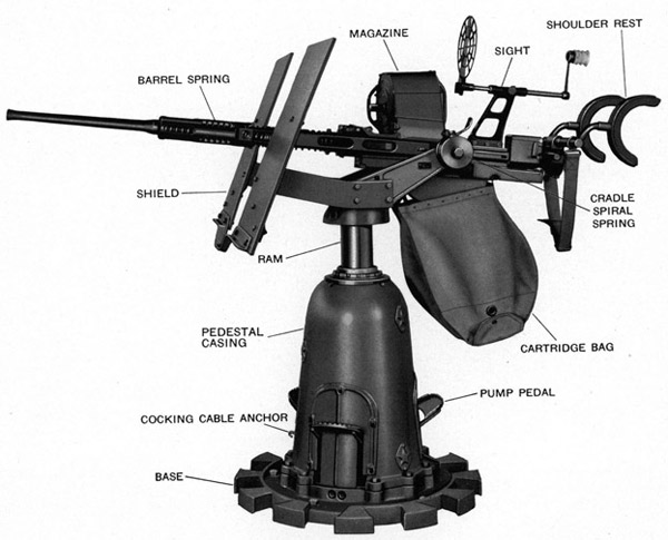
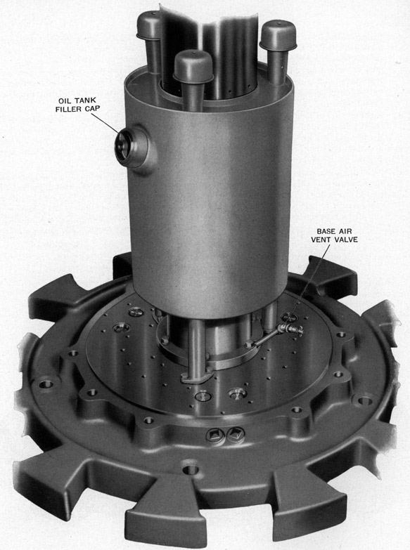
Figure 25-Exterior view showing general arrangement
of the 20 mm. A.A. Gun and Mount Mark 6
79
Chapter 5 MARK 6 GUN MOUNT
GENERAL DESCRIPTION
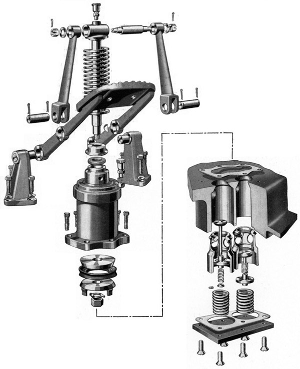
This gun mount, see Figure 25, is hydraulically operated by three pedals, equally spaced around the pedestal. Operating any one of the pedals will permit raising and lowering the trunnion to enable the gunlayer to assume the easiest position to fire at any elevation.
The gun carriage is locked against rotation when lowered. After being raised approximately one half inch, the gun can be trained through an unlimited angle.
The gun can be elevated on its trunnions between minus 15 degrees and plus 90 degrees. The Gun Mount comprises the following general units:
1. The base, ram cylinder, and pedestal casing which support and enclose the mechanism.
2. The ram, carriage, and cradle which raise and lower the gun and rotate with it.
3. The hydraulic operating and control mechanism which provides means of raising and lowering the ram.
DETAILED DESCRIPTION
The main view of Plate 3 folded at page 12 is a vertical cross section view of the mount.
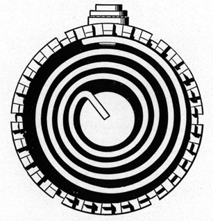
Section A-A is a cross section view of the cradle and the counterbalance spring.
Section B-B is a cross section view of the cartridge bag weight attachment to the cradle.
Section C-C is a cross section view of the cradle locking plunger arrangement.
Section D-D is a cross section view of the oil pump and valve arrangement.
Section E-E is a detailed view showing the cylinder base air vent.
Section H-H is a detailed view showing the anchor on the pedestal for attaching the cocking rope.
Reference to Plate 3 folded at page 120 will be helpful in identifying the various parts mentioned.
BASE
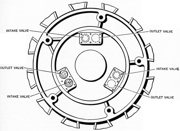
The base which acts as a support for the pedestal casing, oil tank, ram cylinder, hydraulic pumps, and pump pedal brackets, also houses the intake and outlet valve groups. Cut-outs are provided on the outer edge of the base to give the gun layer solid foot holds when firing the gun at high elevation.
RAM CYLINDER
Centered in the pedestal casing and bolted to the base, the ram cylinder serves two purposes. Its upper third acts as a guide or bearing for the ram with its attaching carriage and cradle, while its lower two-thirds forms the ram cylinder proper. A shoulder formed at the junction of the guide and cylinder acts as a stop for the ram piston and limits the upward travel of the ram.
A leather oil seal pressed into the recess machined in the upper end of the ram cylinder serves to wipe off the ram as it is lowered. A close fitting ice breaker lip is provided on the top of the seal to remove ice which may form on the ram when it is raised.
A tapered sleeve screws onto the upper end of the ram cylinder and centers it by engaging in a tapered bore in the casing. Four Allen type set screws threaded into the side of the casing, near the top, prevent the sleeve from turning out.
80
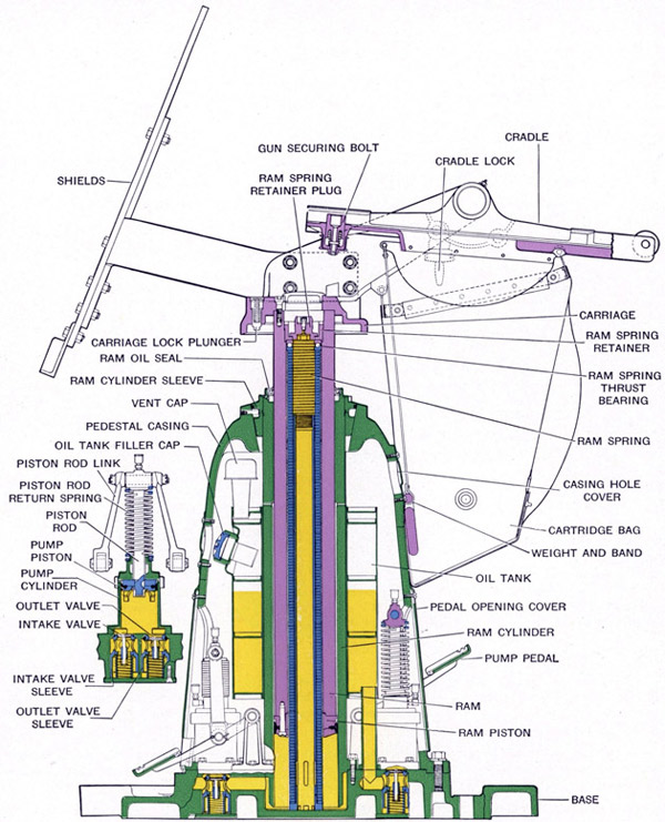
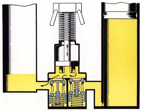
Figure 26-Sectional view of Mark 6 Mount (ram partially raised)
81
PEDESTAL CASING (STAND MARK 6)
The pedestal casing which completely surrounds the operating mechanism is bolted to the base. It is provided with three large removable pedal opening covers, held in place by five machine screws, which permit access to the pumps for lubrication and servicing. There are also four smaller hole covers, each held in place by two machine screws-two to cover the holes near the top provided for the lifting hook used when raising the casing off the base or when lifting the entire unit, one near the center for access to the oil tank filler cap, and one near the base for access to the base air vent valve.
RAM
The ram, which supports the carriage, raises and lowers in the ram cylinder. Power for raising the ram is furnished by three hydraulic pumps. Bolted to the lower end of the ram are the steel piston of slightly larger diameter than the ram, a synthetic rubber piston cup, and a steel piston cup retainer.
Contained within the ram is a ram spring and tube assembly, the purpose of which is to aid the hydraulic mechanism in raising the ram and gun and cushioning its downward travel. This assembly consists of five rectangular wire coil springs, separated from one another by steel spacer washers. At the lower end of the tube the springs are retained by a flange welded to the tube. These springs act against the upper end of the ram through a ball thrust bearing and a cup shaped retainer which screws into the internal threads in the ram. A retainer plug fitted with a bleeder valve is screwed into the retainer. This plug serves two purposes. When in its normal position the short, large diameter end is threaded into the retainer and it acts as a plug to prevent loss of oil. Its other purpose is to confine the ram springs when removing the ram spring and tube assembly from the ram to service the unit. For this purpose the plug is removed and inverted so that its long, small diameter end is threaded into the internal threads at the upper end of the tube. Very definite instructions must be followed when servicing this assembly to prevent injury to the personnel. Carefully read the instructions under "Ram Spring and Tube Assembly-Removal", page 96, and "Ram Spring and Tube Assembly-Stripping", page 100.
CARRIAGE MARK 6
This carriage is similar to Mark 5 carriage used on Mark 5 mounts except that the arms extend 2" farther backward and 2 7/8" farther upward. Also there is no boss on the front end for the carriage lock lever. There is, however, a hole in which a spring loaded carriage lock bolt operates to lock the carriage against rotation when the ram is lowered. The operation of this carriage lock is explained in detail on page 83.
CRADLE MARK 5
The cradle used on Mark 6 mounts is similar to that used on Mark 5 mounts. Although the overall length is approximately the same length as cradle Mark 4 Mod. 2, it is one inch longer from the center of the cradle trunnion pin hole to the rear end. The two holes provided in the right side for the cradle lock plunger are relocated to permit the cradle to be locked in the 5 degree or 90 degree elevation positions. The operation of the cradle lock is described on page 83.
HYDRAULIC OPERATING AND CONTROL MECHANISM
The hydraulic operating and control mechanism consists of the oil tank, oil pumps, pump pedals, and the intake and outlet valves located in the base. See Figure 27.
Oil Tank
The oil tank is of approximately five gallons capacity and surrounds the ram cylinder. It is mounted on the base through three equally spaced hollow supports which act as outlets for the oil drawn from the tank through drilled passages in the base to the intake valve chambers. Three vent caps are pressed into place on three equally spaced vent tubes projecting from the top of the tank. An oil tank filler, fitted with
82
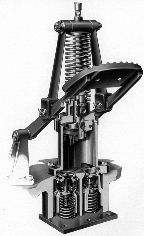
Figure 27-Cut-away view of oil pump and valves
83
a strainer is located near the top of the tank and is accessible through a hole near the center of the pedestal casing. A filler cap with gasket is screwed into the filler neck.
Oil Pumps and Pump Pedals
Three oil pumps, one opposite each of the pedals, are located on the base inside of the casing. Each pump includes a cylinder bolted to the base casting, a piston, piston cup, piston cup retainer, and a piston rod. A heavy coil wire spring holds the piston normally at the top of its travel while suitable linkage connects the piston rod and pedals. Four fingers are provided on the bottom of the piston for the purpose of opening the valve sleeves when the pedal is operated in the lower range of travel.
The piston cup, which is clamped between the piston and piston cup retainer, fits the pump walls snugly and prevents leakage between the piston and cylinder.
A porous bronze bushing in the top of the pump centers and guides the piston rod as it travels up and down. At the upper end of this bushing is a felt packing and retainer which acts as a wiper.
Pump Valves and Valve Sleeves
One pair of intake and outlet valves, each operating in a sleeve, is located in the base directly below each oil pump. Relatively heavy coil springs press the valve sleeves upward against seats in the base with enough force so that the oil pressure in the cylinder will not cause them to move downward and permit oil to escape.
Both intake and outlet valves have stems that are a sliding fit in guides which center them in the sleeves and each valve is equipped with a relatively light spring which tends to hold it in the closed position. Each valve as well as each sleeve has a rubber seal moulded into the seat to insure positive sealing. These seals are made of synthetic rubber which is not affected by oil.
The important thing to bear in mind at this point is that the intake and outlet VALVES function in the operation of RAISING the ram, whereas the intake and outlet valve SLEEVES function in the operation of LOWERING the ram. All details of these operations are covered in "Description of Hydraulic Operation," page 89, and are, therefore, not repeated here.
CARRIAGE LOCK
This lock is of the spring loaded plunger type and is built into the front end of the carriage. It consists of lock plunger (299943-1), plunger spring (299943-2), lock cover (299943-3), and cover retainer (299943-4). See Main Section View, Plate 3.
The plunger slides in a bored hole in the carriage and is held in the downward position by the spring which sets in the bore machined in the plunger. The cupped shaped cover placed over the spring to hold it under tension, is secured by the retainer which sets in a groove in the plunger hole. This lock operates automatically when the carriage is lowered.
CRADLE LOCK
The cradle lock, which permits locking the gun in the plus 5 degree and plus 90 degree positions is built into the right side of the carriage. The plunger (299943-5), slides in a vertically bored hole in the carriage and engages in one of the corresponding holes in the cradle. This plunger is operated by lock lever (OE-3512), see Section C-C, Plate 3, which is mounted on pin (OE-3513) in its boss in the carriage. Two spacers (OE-3518), one located on each side of the lever, prevent the lever from shifting sideways. A rubber bellows type water seal (OE-3519) is stretched over the lever and its boss on the carriage to exclude dirt and moisture from the plunger.
A spring loaded locking ball arrangement consisting of ball (OE-3511), spring (OE-3516), and screw (OE-3517) holds plunger (299943-5) in either the locked or unlocked position.
84
GUN SECURING BOLT
This bolt is the same as used on Mark 4 Mod. 2 Mount to lock the gun in the cradle. For complete description see page 22. Also see Main Section View, Plate 3.
CARTRIDGE BAG
The cartridge bag and weight are the same as used on Mark 4 Mod. 2 Mount. See page 22 for complete description.
85
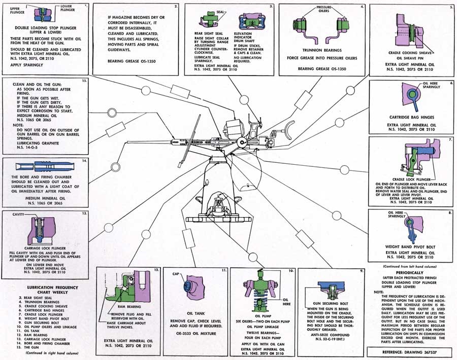
LUBRICATION
Figure 28-Lubrication chart Mark 6 Mount
86
ALL OILERS, PEDAL LEVER PIVOT BEARINGS, AND LOCK PLUNGERS SHOULD BE WELL LUBRICATED ACCORDING TO DETAIL INSTRUCTIONS THAT FOLLOW, USING EITHER EXTRA LIGHT MINERAL OIL, NAVY SYMBOL 1042, 2110 OR 2075, OR OIL MIXTURE (OE-3533) AS SPECIFIED FOR THE HYDRAULIC SYSTEM. SEE FIGURE 28.
CRADLE LOCK PLUNGER (299943-5)
With cradle rotated to vertical position, oil end of plunger that engages the cradle, using an oil can, and force oil into carriage bearing by operating lock lever back and forth a few times. Also remove the water seal from the lever and supply a few drops of oil to the plunger, end of lever, and lever pivot. Wipe off any excess oil that runs down before reinstalling the seal.
CARRIAGE LOCK PLUNGER (299943-1)
Raise carriage about 12 inches, reach under carriage, and using one hand, push up on the lower end of the carriage lock plunger until it reaches its upper limit of travel. Hold the plunger in this position and fill the plunger cavity on top of the carriage with oil. Then allow the lower end of the plunger to drop down slowly. This action will draw the oil from the cavity into the plunger hole. Repeat until oil appears on bottom end of plunger. It is not necessary to remove the plunger spring cover and retainer unless oil fails to appear on lower end of plunger by the method described.
HYDRAULIC SYSTEM-OIL TANK
At least once a week, remove filler cap, check oil level, and add Oil Mixture OE-3533, if necessary.
PISTON ROD BEARINGS
Loosen five cover screws in each cover and lift off covers.
Six oil cups-two on each pump, one on the upper end of the piston rod to lubricate the upper end of the rod to pivot pin bearing and the other in the pump cylinder to fill the oil well around the slightly porous cylinder bushing-unscrew covers and fill cups with specified oil.
PEDAL LEVER PIVOT BEARINGS
Twelve bearings-no oilers-oil pedal to link and pedal to lever bracket pin bearings using an oil can. Reinstall covers and tighten screws.
RAM BEARING
A circular oil well is provided at the top of the ram cylinder. Raise the carriage about 12 inches, remove the 1/4 inch oil well plug from the top of the ram cylinder, fill oil well with specified oil, using an oil can and reinstall plug. Raise and lower carriage a few times to permit oil to spread completely over ram bearing.
GUN SECURING BOLT
Just before the gun is installed in the cradle thoroughly coat gun securing bolt and the inside of the securing bolt hole in the breech casing with Anti-seize compound, Navy Specification 52-C-19 (Int.).
CRADLE COCKING SHEAVE
Spin the sheave by hand and with an oil can force oil to sheave pin.
USE (OS-1350) GREASE IN PRESSURE OILERS AS INDICATED BELOW. SEE FIGURE 28.
CRADLE TRUNNION PINS (OE-2161 and OE-2160)
Force grease into pressure oilers (OE-2259) using grease gun (OE-1637).
87
OPERATION OF MOUNT
TO RAISE THE CARRIAGE
Pump one or more of the three pedals up and down through the lifting stroke (upper four-fifths of the total travel). Rapidity of raising depends on the number of pedals operated and the speed at which they are pumped.
The first stroke of the pedal will raise the ram and carriage sufficiently for the carriage lock plunger to clear the notch in the ram cylinder sleeve and permit the gun to be trained to any position.
TO LOWER THE CARRIAGE
Depress one or more of the pedals beyond the resistance point felt at the end of the lifting stroke_ Release the pedal when the carriage reaches the desired position. The speed of lowering is controlled by the number and position of the pedals operated.
When the ram is at its extreme upper limit of travel, extra pressure is required on the pedals for releasing. Explanation of this condition is given under "Lowering the Ram", page 91.
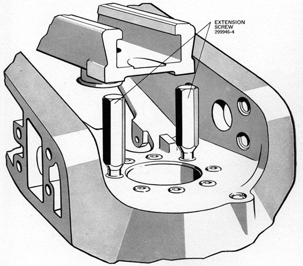
Figure 29-Carriage extension screws (299946-4) in place
88
The carriage is locked against rotation by completely lowering the ram and rotating it slightly until the tip of the carriage lock plunger drops into one of the notches provided in the ram cylinder sleeve.
SPLINTER BULWARKS
In some ships where 38 inch bulwarks are provided around the circumference of the mount working circle, it is necessary to use a stop to reduce the depression of the gun to approximately 3 1/2 degrees (normal depression is 15 degrees). For this purpose two special extension screws (299946-4) are provided with each mount. When these are required, remove two center rear carriage to ram screws (299946-1) and replace them with the extension screws shown in Figure 29. This provides a stop for the front end of the cradle.
89
DESCRIPTION OF HYDRAULIC OPERATION MOUNT
To obtain a complete understanding of the manner in which the hydraulic system operates note carefully the detailed information and illustrations that follow:
Assume first that the hydraulic system is full of oil, that it has been bled of entrapped air for satisfactory operation, and that the ram is at the lower end of its travel.
RAISING THE RAM
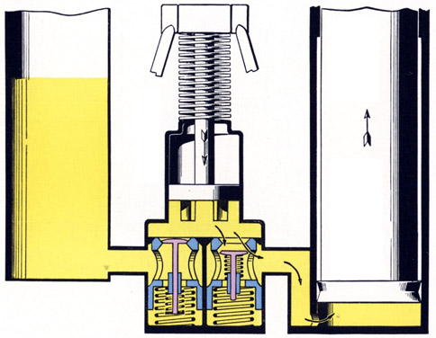
Pressing any one of the three pump pedals down through the upper four-fifths of its stroke forces the piston rod and its piston downward against the tension of the piston rod return spring. See Figure 30.
The oil pressure created in the pump cylinder forces the outlet valve downward from its seat in the sleeve. The oil displaced from the cylinder passes between the valve and its seat, through the sleeve and the passage in the base, into the bottom of the ram cylinder. The ram is forced upward a distance proportional to the amount of oil displaced from the pump.
Figure 30-Lifting stroke-pump discharging
oil into ram cylinder
90
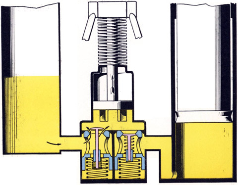
As foot pressure is released from the pump pedal for the upward stroke, the tension on the piston rod return spring moves the piston rod and its piston upward. See Figure 31.
Figure 31-Intake stroke-drawing oil into pump cylinder
This releases the pressure on the outlet valve and it is returned to its seat in the sleeve by the tension of the light valve spring, trapping the oil in the ram cylinder and holding the ram suspended. At the same time the vacuum created in the pump cylinder lifts the intake valve off its seat in the sleeve, against the tension of the light spring. Oil is then drawn from the tank, between the intake valve and its seat in the sleeve and into the pump cylinder. When the cylinder becomes full of oil, the intake valve is returned to its seat by the drop in vacuum and the tension of the light valve spring. The pump is now ready for the next downward stroke.
91
LOWERING THE RAM
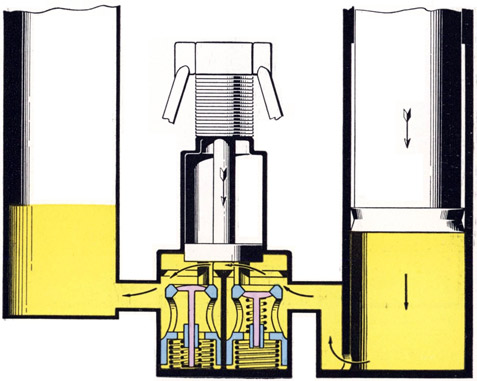
When the pump pedal starts through the lower range of pedal travel fingers on the bottom of the piston contact the upper edges of both intake and outlet valve sleeves. As the pedal is pressed downward the valve sleeves are forced off their seats in the base. See Figure 32.
This leaves a clear passage for oil, under pressure of the weight of the ram, to flow from the ram cylinder to the oil tank. Bottoming of the piston rod nut on the base determines the lower extremity of pedal travel.
Figure 32-Valve sleeves forced off seats in base-ram
discharging oil back into tank
92
While the foregoing conditions are true when lowering the ram from any partially raised position, a slightly different set of conditions are encountered when attempting to lower it after having forced it to its extreme upper position. In this case, the pump has a full charge of oil but it cannot be discharged through the outlet valve since the ram is already against its stop. See Figure 33. By applying extra force to the pedal, however, sufficient hydraulic pressure will be built up in the pump cylinder to force the intake valve sleeve down compressing the heavy sleeve spring, allowing the oil in the pump to return to the tank. Following this the piston fingers can function in opening the valve sleeves as described previously. See Figure 32.
Figure 33-Ram at top of stroke-pump
discharging oil back into tank
93
STRIPPING
The following instructions for stripping the Mark 6 gun mount should be followed in the order given to prevent damage to the parts and injury to the personnel doing the work. Before beginning any operation read the entire procedure for that operation.
Operations which require particular care to prevent accidents include those in which the ram spring and tube assembly (299928) is removed from the gun mount and subsequent stripping of this unit. No sizeable item mounted on the ram, including the carriage, cradle, and shields should be removed unless the ram springs (299929-1) have been confined by removing the ram spring retainer plug (299930-1) and reinstalling it in an inverted position as covered by Operations 6 and 7. Minor items of small weight may be safely removed. If a large piece is removed the ram springs will cause the ram to fly up with possible damage to the gun mount or personnel. It is allowable to remove the gun, magazine, shoulder rest or the sight without confining the springs. If the ram spring retainer plug is removed at any time to confine the springs, then it will be necessary to bleed the hydraulic system as covered in operation 35 in "Reassembly."
When the gun has been removed from the cradle extreme care should be taken when moving the cradle back and forth from the 5 degree to 90 degree elevations. Without the gun in the cradle, the cradle spring and cradle weight will cause the cradle to spring down violently. It is best for one man to hold the rear end of the cradle securely while the other disengages the cradle lock.
For location of parts by part number refer to Plate 3-Sectional Detail of Gun Mount-which is folded at Page 120. The various tools required for stripping are listed and illustrated on pages 119 and 120 of this pamphlet.
The gun mount should always be lifted with shipping hook (300003-1), supplied with the mount, by engaging the hook in the two upper pedestal casing holes. Never lift the mount by attaching to the carriage or cradle as this places an excessive load on the edge of the ram piston and may damage the piston.
Operation Number
1. MAGAZINE-Unship the magazine by pushing forward on the magazine catch lever. Uncock the gun.
2. SIGHT-Unship the sight by loosening the three clamping screws (OE-1192), using sight universal spanner (OE-1189). The center screw must be backed out five or six turns and then pushed toward the left side until the stop piece is disengaged from the notch in the breech casing. Then slide the sight assembly back toward the trigger cover and lift it off the gun.
3. CARTRIDGE BAG ASSEMBLY (OE-2198)-Remove the two cartridge bag anchor bolts (OE-2172), nuts (OE-2173), and cotter pins (OE-2231) from the carriage and cradle and remove the bag. This operation can best be done with the gun in the 5 degree position.
4. WEIGHT AND BAND ASSEMBLY (OE-2207)- Raise the gun to the 90 degree position and lock in place with the cradle lock plunger. Remove weight band pivot bolt (OE-2177), nut (OE-2178), and cotter pin (OE-2230) and remove the weight. See Section B-B, Plate 3.
5. DRAINING OIL-Loosen the two lowest pedestal casing hole cover screws (12-Z-41-253) and swing cover (299915-2) to one side. Place a clean container of at least five gallons capacity near the mount. Unscrew the wing nut on base air vent valve (299942-2) a few turns and hold one end of bleeding pipes (299993-7 and 299992-4) over end of the valve and the other end in the container. The hose must be held on the valve as oil pressure will force it off. Pump each pedal slowly until the oil stops flowing.
Pry ram cover (299946-2) from the top of the carriage. Remove ram air vent valve screw (12-Z-8-270) and lock washer (OE-1293) from air vent valve (299930-4). Unscrew air vent valve (299930-4) three turns with wrench (299995-2) and leave open for at least one minute. Close the
94
Operation Number
valve and pump one of the pedals rapidly until the oil stops flowing from the bleeding pipe. This breaks an air-lock and allows the oil to flow out of the center of the ram.
Remove pipes (299993-7 and 299992-4) after the oil had been drained.
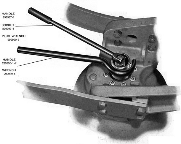
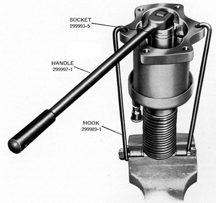
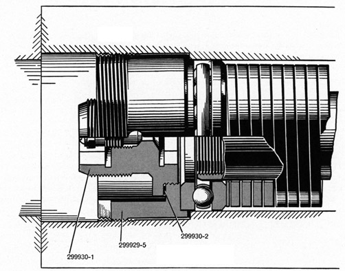
6. RAM SPRING RETAINER PLUG (299930-1) REMOVAL-Place retainer wrench (299989-5) and wrench handle (299990-1) in position on retainer (299929-5) to keep it from turning when removing the plug. See Figure 34. Unscrew and remove retainer plug (299930-1), using retainer plug wrench (299990-3), 7/8" inch socket (299993-4), and swivel end wrench handle (299997-1). Drilled end of plug wrench (299990-3) is placed over plug valve (299930). Remove plug gasket (299930-2).
Figure 34-Removing ram spring retainer plug (299930-1)
7. RAM SPRING RETAINER PLUG (299930-1) SAFETY POSITION-Replace plug in inverted position (long end down) in retainer (299929-5), using wrench (299990-3). The engaging threads for this operation are left hand. See Figure 47. Screw the plug in exactly nine turns. This operation confines ram springs (299929-1) in the ram spring and tube assembly so that this unit
95
Operation Number
may be safely lifted from the ram in a later operation. Do not install retainer plug gasket (299930-2) at this time.
8. RAM SPRING RETAINER (299929-5)-Unscrew the retainer from the upper threads of ram (299926-1), using wrench (299989-5) and wrench handle (299990-1). The retainer cannot be removed from the cavity at this time due to interference with the carriage.
9. SHOULDER REST-Press the catch that retains the handgrips and remove the shoulder rest and handgrips by unscrewing counterclockwise.
10. GUN-Disengage cradle lock and lower the gun to the 5 degree position and lock it in place. Pull down on gun securing bolt withdrawing' head (OE-2190) to disengage bolt (OE-2188) from the breech casing and slide the gun out of the cradle to the rear.
11. SHIELDS-Remove shield strap (299951-1) by taking out four bolts (OE-2227) and nuts (OE-2229). Remove the right and left shields as assemblies by taking out four bolts (OE-3535), nuts (OE-2217), and lock washers (OE-2275) attaching each bracket (OE-2220) right and (OE-2221) left to the carriage. One man should hold the shields while another is removing the bolts.
STRIPPING SHIELD ASSEMBLIES-
Stripping the shield assemblies, if necessary, is accomplished as follows: Remove four bolts (OE-2228) and nuts (OE-2229) attaching the brackets to the shield plates.
12. CRADLE ASSEMBLY (299947)-Raise the cradle to the 90 degree position and lock it in place with the cradle locking plunger. Cradle spring and cradle weight will cause cradle to spring down violently. Handle with care. Remove cradle spring housing retaining nut pin (OE-2268) by driving it out with a punch. See Section A-A, Plate 3. Unscrew and remove retaining nut (OE-2163), using wrench (OE-2904).
NOTE-When the spiral spring and housing assembly was assembled to its cover (OE-2165), it was turned clockwise one notch before its serrations were engaged with those of the cover to keep spring (OE-2169) under tension. Keep hands clear of serrations when stripping to prevent injury.
Pull off the housing and spring assembly.
Remove the housing cover by taking out four screws (OE-2256). Drive out cradle trunnion pin securing nut pin (OE-2269) with a punch. Remove retaining nut (OE-2162), using wrench (OE-2904 and spanner OE-3157). Drive both cradle trunnion pins (OE-2161) right and (OE-2160) left inwards, and remove from their holes. Lift off the cradle. Key (OE-2191) in trunnion pin (OE-2160) is a press fit in the pin and should not be removed. Any attempt to remove it will result in damaging the pin.
STRIPPING CRADLE ASSEMBLY-
Stripping the cradle assembly, if necessary, is accomplished as follows: Remove cheek plates (299947-1) right and (299947-2) left by taking out four screws (OE-2263) from each plate. See Section A-A, Plate 3. Unscrew and remove oiler (OE-2259). Drive out gun securing bolt withdrawing head pin (OE-2261), using a punch and take off head (OE-2190). The bolt (OE-2188) and spring (OE-2189) can then removed. Drive pin (OE-2262) out of bolt (OE-2188), using a punch. Drive out cocking sheave pin taper pin (12-Z-49-63) from underneath. Drive out cocking sheave pin (299950-3) and remove sheave (299950-2).
STRIPPING CRADLE SPRING AND HOUSING ASSEMBLY-
To strip cradle spring and housing (OE-2312), proceed as follows: Remove spring anchor bolt (OE-2168) and its lock washer (OE-2278). See Section A-A, Plate 3. Spiral spring (OE-2169)
96
Operation Number
can then be removed. Bushing (OE-2166) is pressed in the housing and should not be removed unless it is desired to replace the bushing.
13. RAM CYLINDER SLEEVE (299925-1)-Using Allen wrench (299993-2), unscrew and remove the four cylinder sleeve set screws (299925-2) located near the top of the pedestal. With ram in lowest position so that carriage lock plunger (299943-1) is engaged in one of the notches provided in the cylinder sleeve, turn the carriage counterclockwise, as viewed from the top. Continue turning the carriage until the sleeve is disengaged from the cylinder as evidenced by the sleeve no longer raising when it is turned.
14. CARRIAGE ASSEMBLY (299943)-Remove two opposite carriage to ram screws (299946-1), using socket (299992-2) and swivel end wrench handle (299997-1). If it is necessary to tap the bottom of the carriage slightly to break it loose from the ram, install the two pilot screws (299989-4). These screws will prevent the carriage from falling off the ram when it breaks loose.
STRIPPING CARRIAGE ASSEMBLY-
Stripping the carriage assembly, if necessary, is accomplished as follows: Unscrew and remove oiler (OE-2259). Press down on lock cover (299943-3) and remove retainer (299943-4) with a pair of pliers. Be sure to hold one hand over the cover when removing the retainer to prevent the spring popping the cover up into the air. Remove spring (299943-2) and plunger (299943-1) from carriage. See Main Section View, Plate 3.
Remove lock spring and ball retainer screw (OE-3517), spring (OE-3516), and ball (OE-3511). Remove carriage lock lever water seal (OE-3519). Drive out lock lever pivot pin (OE-3513), using a punch and remove lever (OE-3512) and two spacers (OE-3518). See Section C-C, Plate 3. Pull out plunger (299943-5). Hole cover (OE-3514) should not be removed unless it is necessary. This is an expansion type plug and can be driven out with a drift inserted from underneath.
15. RAM CYLINDER SLEEVE (299925-1)-Lift sleeve off top of pedestal. Carefully examine sleeve packing (299925-3). If damaged, it can be removed by prying it out of groove in sleeve.
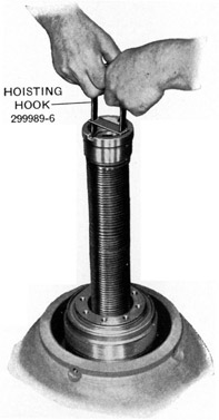
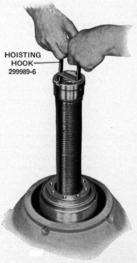
16. RAM SPRING AND TUBE ASSEMBLY (299928) REMOVAL-Engage the two round lugs on outside of hoisting hook (299989-6) in the two holes provided in ram spring retainer (299929-5). Be sure that the horizontal cross bar on the hook rests on the top edge of the retainer. See Figure 35. With both hands, carefully raise the spring and tube assembly out of the ram. If the ram is raised with the springs, tap it lightly on top with a soft face hammer. Remove retainer gasket (299930-3).
17. PEDAL OPENING COVER (299916-1)-Loosen five screws (12-Z-41-253) attaching each pedal opening cover to the pedestal and lift off the covers.
Figure 35-Lifting ram spring and tube assembly from ram
97
Operation Number
18. PEDESTAL CASING (299913-1)-Loosen the two casing hole cover screws (12-Z-41-253) in each cover (299915-2) at the top of the pedestal and swing the covers to one side. Remove the nine pedestal to base screws (299915-4) and lock washers (12-Z-22-257), using 1 inch socket (299993-6) and swivel end wrench handle (299997-1). Engage hook (300003-1), shipped with the mount, into the two lifting holes near the top of the pedestal. With a chain fall or hoist, carefully raise the casing off the base.
19. PUMP PISTON ROD LINK (299940-6) -Remove cotter pins (12-Z-48-639) from link pins (299940-7) and push pins out of the links. See Section D-D, Plate 3. Remove cotter pins (12-Z-48623) from each end of piston rod link pivot pins (299940-1) and remove nuts (299940-2) and washers (12-Z-22-274), using box wrench (299996-2), 5A inch socket (299995-5), and swivel end wrench handle (299997-1). Remove piston rod links and push pivot pins out of piston rods.
20. PUMP LEVER BRACKET ASSEMBLY (299919)-Remove three bracket to base screws (12-Z-46-244) and lock washers (OE-2271), using 5/8" socket (299995-4) and crank type wrench handle (299996-1), from each of the six brackets and remove the brackets from the base. See Main Section View, Plate 3. The three pedal assemblies can now be slipped off the bracket pivot pins.
21. PUMP ASSEMBLIES-With 9/16" socket (299995-4) and swivel end wrench handle (299997-1) remove the eighteen pump cylinder to base screws (12-Z-46-244) and lock washers (OE-2271) and remove the pump assemblies from the base. Remove the cylinder gaskets (299941-1). See Main Section View, Plate 3.
STRIPPING PUMP ASSEMBLIES-
Strip pump assemblies, if necessary, as follows: Remove oiler (299938-5) from end of piston rod. Invert the pump and clamp the upper end of the piston rod in a vise. Insert piston rod pivot pin (299940-1) in rod. Turn cylinder assembly 90 degrees on the piston rod, to align the side holes of the cylinder base with the pivot pin. Compress the piston return spring (299939-5) by having two assistants pull the cylinder down with a bar placed over the base. Align this bar so that ends of pump piston do not strike bar and restrict its downward travel. Place one piston rod assembling hook (299989-1) over each end of the piston rod pivot pin and engage the hooks in the center holes of the cylinder base. Install nuts (299940-2) on each end of pivot pin (299940-1). See Figure 36.
Bend down the tab on piston rod nut washer (299939-4) from nut (299939-2). With 15/16" socket (299993-5) and swivel end wrench handle (299997-1) remove piston rod nut and washer. Again compress piston rod return spring with bar and remove hooks. Remove piston (299939-3), cup (299939-1), cup retainer (299938-3), cylinder assembly (299937), and return spring (299939-5) from piston rod. See Section D-D, Plate 3. It is not necessary to remove woodruff key (299938-4) from the piston rod. Remove cylinder packing retainer (299937-5), packing (299937-6), oiler (299938-5) and oiler elbow (12-Z-322-8) from cylinder. Cylinder bushing (299937-2) should not be removed from the cylinder unless it is desired to replace it. Cylinder vent cover (299937-1) also should not be removed. Remove the pivot pin from the rod and the rod from the vise.
22. BASE AIR VENT-Remove air vent valve (299942-2), elbow (299942-4) and pipe (299942-3) from the cylinder base. See Section E-E, Plate 3.
23. OIL TANK ASSEMBLY (299931)-Remove the six screws (12-Z-46-221) and lock washers (OE-2270) attaching the oil tank to the base, using 1/2" socket (299995-3) and crank type wrench handle (299996-1). Lift tank off base over ram cylinder. Remove the three oil tank outlet pipe gaskets (299933-4). See Main Section View, Plate 3.
98
Figure 36-Stripping oil pump assembly
Operation Number
STRIPPING OIL TANK ASSEMBLY-
Strip the oil tank, if necessary, as follows: Unscrew filler cap (299936-4) and remove gasket (299936-5), using socket (299992-2) and swivel end wrench handle (299997-1). Using a sharp tool or a knife pry out strainer retainer (299936-3) and remove strainer (299936-6). Remove the three vent cap assemblies (299935) by pulling them off the vent tubes.
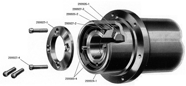
24. RAM (299926-1) AND RAM CYLINDER (299924-1)-Remove the six cylinder to base screws (12-Z-46-263) and lock washers (12-Z-22-254), using 5/8" socket (299995-5) and crank type wrench handle (299996-1). Fasten ram hoisting bar (299991-1) to top of ram (299926-1) with two screws (299946-1). Lift the ram, and the cylinder off the base with a hoist or chain fall. When lifting the ram, the ram piston will pick up the ram cylinder by striking the internal shoulder located just above the row of vent holes. Remove cylinder gasket (299923-5).
25. RAM (299926-1)-Lay the ram cylinder on its side, remove hoisting bar from the ram, and push the ram out through the bottom of the cylinder.
STRIPPING RAM-
Strip the ram, if necessary as follows: Again fasten hoisting bar (299991-1) to top of ram with two screws (299946-1) to serve as a handle. With a screw driver remove the four ram piston screws (299927-4) from the ram. Lift off ram cup retainer (299927-1), cup (299927-2), piston (299926-2), and gasket (299927-3). See Figure 43. Remove the hoisting bar and screws from the ram.
99
Operation Number
26. RAM CYLINDER (299924-1)-Ram oil seal (299923-6) should not be removed from the cylinder unless it is to be replaced. If necessary to remove it, pry it out with hoisting bar (299991-1).
Remove oil well plug (299923-7) with a screw driver.
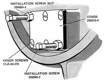
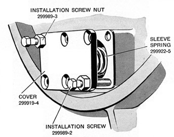
27. BASE ASSEMBLY (299912) STRIPPING-The base has now been stripped of all parts except the valves. If necessary to remove them, proceed as follows: Turn the base upside down and remove two valve chamber cover screws (12-Z-42-276) from opposite corners of the cover. See Figure 37.
Figure 37-Installation screws and nuts in place
Install in their place the two valve chamber cover installation screws (299989-2) with nuts (299989-3) threaded on them until they bottom in holes and draw the nuts down tight against the
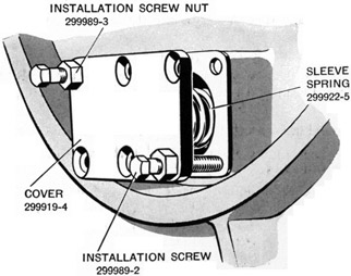
Figure 38-Removing valve chamber cover
100
Operation Number
cover. Remove the balance of the cover screws and then back off nuts (299989-3) alternately with 3/4" deep socket (299993-3) until the spring pressure is released. See Figure 38. If the sealer used on the cover gasket holds the cover to the base, tap the cover lightly on the edge with a soft face hammer before backing off the nuts too far. Remove the installation screws and nuts, cover (299919-4), and gasket (299919-6). Withdraw the two valve sleeve springs (299922-5), valve sleeves and valves from their cavities.
Repeat this operation at each of the remaining two valve chamber covers.
Turn the base over and remove the six base headless pipe plugs (12-Z-329-94) using swivel end wrench handle (299997-1).
28. INTAKE VALVES-Strip the intake valve and sleeve assemblies by compressing valve spring seat (299923-1) and spring (299923-2) with the fingers and removing retainer (299922-6). Remove the seat, spring, valve guide (299922-2), and valve (299921) from sleeve assembly (299920-1). See Figure 40.
NOTE-The rubber on the valves and valve sleeves is moulded on at the time of manufacture and cannot be removed without destroying the pieces.
Repeat this operation on each of the remaining two intake valve and sleeve assemblies.
29. OUTLET VALVES-Stripping of outlet valve and sleeve assemblies requires no mechanical operations. Push outlet valve (299922-1) downward in sleeve assembly (299920-3) and guide (299922-2), spring (299923-2), and outlet valve (299922-1) will come out of the sleeve. See Figure 40.
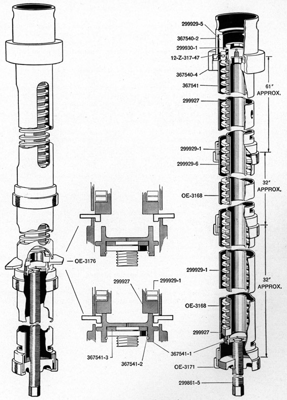
The ram spring and tube assembly (299928) must not be stripped unless compressing tool assembly (367539), Figure 18, is used.
The procedure for this operation is as follows:
30. Place adapter (367540-2) on upper end of long tube assembly (367541) being sure to engage lugs on adapter in slots in end of tube. Slide nut (367540-4) over adapter and screw onto threaded end of tube. See Figure 39.
31. Place a piece of round bar-approximately 3/4" in diameter in a vise. Place the holes in the adapter on the end of the long tube over the bar to prevent the tube from turning. Rest the threaded end of the tube on a suitable support.
32. Place the ram spring and tube assembly into the long tube, with the retainer plug (299930-1) entering first.
33. Install tool screw assembly (299861-5) in end of the long tube, being careful to have keyways in nut (OE-3175), Figure 18, fitted over the lugs in the long tube. This nut must seat firmly over the lugs. Lubricate the adapter thrust washer with a few drops of light mineral oil, Navy Symbol 1042, 2075 or 2110.
34. Slide compressing tool nut (OE-3171) over end of tool screw and thread it onto the long tube.
NOTE-This nut has to hold the entire load of the ram springs and must be turned down all the way on the threads of the long tube.
35. Install tool wrench brace assembly (OE-3180) on the end of tool screw (299861-5) and turn it until adapter (367541-1) on the end of the screw contacts the flange of ram spring tube assembly (299927). Turn the wrench brace clockwise a few more turns, just enough to compress the ram springs to take their load off retainer plug (299930-1). See Figure 39.
36. Lift the long tube off the bar. Have a helper hold the long tube and remove plug (299930-1), using retainer plug wrench (299930-3), 7/8" socket (299993-4), and wrench handle (299997-1), inserted through the end of the tube. Place the tube back on the round bar that is in the vise.
101
Figure 39-Stripping ram spring and tube assembly
102
Operation Number
37. Turn the wrench brace counter-clockwise until the flange of the tube is just short of the transverse slots, Figure 39, in the long tube. Insert stop plate (OE-3176) in the transverse slots in long tube (367541).
NOTE-Lugs (Z), Figure 18, on the stop plate must be toward wrench end of tube. This is necessary to provide a positive lock.
38. Turn wrench brace counter-clockwise again until the spring pressure is resting on the stop plate just installed. See Figure 39.
NOTE-It is necessary that the coils of the springs be free from binding or cocking during the stripping operation. Use a soft hammer and tap on the springs through the slots in the tubes. Do this whenever there is any indication of binding.
39. Unscrew compressing tool nut (OE-3171) from the end of the long tube installed in Operation 34. Remove wrench brace (OE-3180) and the screw assembly (299861-5) from the long tube.
40. Install one short tube assembly (OE-3168) on the long tube assembly being certain that the lugs (X) in the long tube engage in the slots (Y) in the short tube, see Figure 18. Complete seating the lugs in their slots to prevent the tubes twisting during stripping of the springs.
41. Screw tube nut (OE-3171) onto the threaded end of the long tube to join the two tubes, making sure that the lugs remain engaged in their slots.
42. Install the tool screw assembly as instructed in Operation 33. Install wrench brace (OE-3180) on the end of the tool screw.
43. Turn wrench brace clockwise enough to release the spring load on stop plate (OE-3176) and remove the plate.
44. Turn the wrench brace counter-clockwise until the flange of the tube is just short of the transverse slots in the short tube installed in Operation 40. Insert stop plate (OE-3176) in transverse slots with lugs toward wrench brace. Turn brace counter-clockwise until spring load rests on stop plate (OE-3176).
46. Install the second short tube assembly (OE-3168) as instructed in Operation 40 and repeat Operations 41 through 45.
NOTE-If there is any indication of the springs binding, tap them through the long slots in the tube, using a soft hammer.
47. The following parts can now be withdrawn from the tool assembly: Ram spring tube assembly (299927), the five ram springs (299929-1), four ram spring spacers (299929-6), upper thrust bearing (12-Z-317-47),, and retainer (299929-5).
103
REASSEMBLY
Figure 40-Exploded view of oil pump, pump pedal, and valves
104
The following instructions for reassembling the Mark 6 gun mount cover the complete reassembling of the mount starting with all serviceable units completely stripped. (For repairs on ships some units will be supplied as assemblies ready for installation.) The following operations should be performed in the order given to prevent accidents and injury to either the gun mount or the service personnel. Before beginning any operation read the entire procedure for that operation.
Extreme care must be taken during the reassembling and installation of ram spring and tube assembly (299928). The springs (299929-1) are compressed with a force of over five hundred pounds and if allowed to fly apart can do serious damage to adjacent objects. After installation in the gun mount ram spring retainer plug (299930-1) should not be removed from this assembly until the carriage, cradle, and shields have been installed on the ram. The weight of these items is necessary to keep the ram from flying up under the force of the unconfined springs. It is not necessary to have the gun, the shoulder rest, the magazine or the sight in place before uncapping the ram springs.
New lock washers, cotter pins, and composition gaskets should be used at every build-up, or at the installation of any part. All composition gaskets should be coated on both sides with sealer (299998-4) before they are installed. All old gasket material must be scraped off clean before new gaskets are installed, and extreme care should be taken to keep all parts clean and free of dirt or grit. The oil mixture (OE-3533) for use in the hydraulic system must be kept free of water and dirt and should be handled in a clean container only.
For location of parts by part numbers refer to Plate 3-Sectional Details of Gun Mount-which is folded at Page 120. The various tools required for reassembling are listed and illustrated on Pages 119 and 120.
Before reassembling, dip all parts such as pump valves, sleeves, guides and piston cups in oil mixture (OE-3533). Also coat all bearings and pivot pins with the same oil at the time of reassembling to assure adequate initial lubrication. Figure 40 is an exploded view of the oil pump, pedal, and valve parts.
The gun mount should always be lifted with shipping hook (300003-1) supplied with the mount. It should never be lifted by attaching to the carriage or cradle as this places an excessive load on the edge of the ram piston and may damage the piston.
Operation Number
1. BASE ASSEMBLY (299912)-Clean base (299917-1) carefully, including interior oil holes, and make certain there are no burrs in the valve sleeve holes. All old gasket material must be scraped off. Coat the threads of the six base headless pipe plugs (12-Z-329-94) with sealer (299998-4). Install the plugs in the base, using swivel end wrench handle (299997-1).
2. PUMP VALVES-OUTLET-Turn the base upside down, dip outlet valve sleeve assemblies (299920-3) in oil mixture (OE-3533) and place them in clockwise holes (as viewed from bottom of base) of each pair of holes. See Figures 40 and 41. Dip outlet valve assemblies (299922-1), springs (299923-2), guides (299922-2), and sleeve springs (299922-5) in oil mixture (OE-3533) and place them in the three outlet sleeve assemblies in the order given.
INTAKE-Make three assemblies of the intake valves. Place intake valve assembly (299921) in intake valve sleeve assembly (299920-1) and install guide (299922-2) in sleeve. Place spring (299923-2) and spring seat (299923-1) on valve stem. Depress the spring and seat with the fingers and slide seat retainer (299922-6) fully into the groove in the stem. Dip the three assemblies in oil mixture (OE-3533) and place them in the counter-clockwise holes of each pair of valve holes. Place the three intake valve sleeve springs (299922-5) in the sleeves.
Coat both sides of valve chamber cover gaskets (299919-6) with sealer (299998-4) and place them on covers (299919-4). Install the two installation screws (299989-2) with nuts (299989-3) threaded on each one through opposite corner holes in the cover and gasket and thread them into the base for at least ten turns. Pull nuts down uniformly with 3/4" deep socket (299993-3). When
105
Figure 41-Valve locations in base
Operation Number
the cover is about one inch from the base, feel under cover with fingers and centralize the sleeve valve springs. See Figure 42. Continue to pull nuts down until the cover is against the base and then install four cover screws (12-Z-42-276). Remove the two special screws and nuts and install in their places two more screws (12-Z-42-276). Tighten screws securely with a screw driver and adjustable wrench (OE-1606). Turn the base right side up. With the handle end of a blunt instrument, such as a hammer, press down on the valve heads once or twice to check their movement.
Repeat above operation at each of the two remaining valve groups.
3. RAM CYLINDER (299924-1)-If oil seal (299923-6) was removed from the ram cylinder replace it with a new one. Place it in the cylinder with the ice breaker lip to the top. Place pilot (299993-1) on the seal and tap lightly in place with a soft face hammer, tapping progressively around the pilot until the seal is all the way in and seated. Do not strike too hard, and do not continue to tap after the seal is seated. Screw oil seal well plug (299923-7) into its hole near the top of the cylinder.
Place ram cylinder sleeve (299925-1) on the cylinder and screw it down until the lip on the oil seal is about 1/8" inside the top edge of the sleeve. Clean the cylinder and seal and stand the cylinder upside down on the floor. Clean off all old gasket material and wipe interior of the cylinder with a clean cloth dipped in oil mixture (OE-3533).
4. RAM (299926-1)-Fasten ram hoisting bar (299991-1) to bottom of ram with two carriage to ram screws (299946-1). Lubricate the exterior of the ram with oil and lower the ram into the cylinder.
106
Figure 42-Centralize springs at this point
Operation Number
Care must be taken to start the ram through the step in the cylinder just below the row of vent holes.
Lay the ram cylinder on its side on a bench, being careful not to damage the cylinder sleeve flange and remove the hoisting bar and screws from the ram.
Slide the ram up into the cylinder about two inches, and fasten hoisting bar (299991-1) to the top of the ram with two carriage to ram screws (299946-1). Coat both sides of ram piston gasket (299927-3) with sealer (299998-4). Place the two pilot screws (299989-4) in opposite screw holes in the bottom of the ram and place the gasket on the end of the ram. Install ram piston (299926-2) against the gasket. Dip piston cup (299927-2) in oil mixture (OE-3533) and place it in the ram cylinder over the pilot screws. Fit the cup against the ram piston, making certain that the ring on
Figure 43-Installing ram piston parts on lower end of ram
107
Operation Number
the cup enters into the groove in the ram piston. See Figure 43. Use a screw driver if necessary to press it into place. Place ram piston cup retainer (299927-1) in the ram cylinder against ram cup (299927-2) and install two ram piston screws (299927-4) in their holes and draw up snugly. Remove pilot screws and install the remaining two screws (299927-4). Tighten the screws securely with a screw driver and adjustable wrench (OE-1606). If the ram is rotated slightly and pushed back and forth several inches while the screws are still a little loose, the piston cup will be better fitted in the ram cylinder.
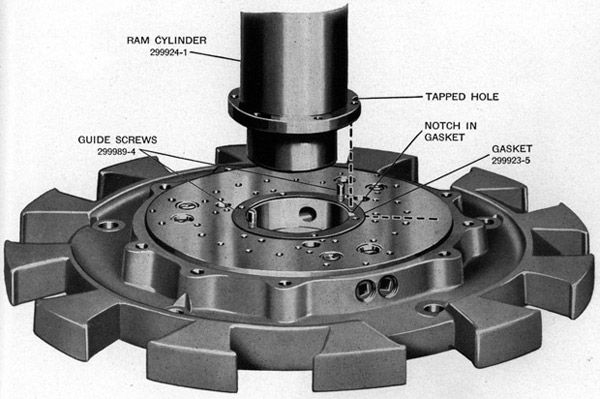
5. RAM CYLINDER (299924-1) -Turn the base right side up and clean the top side and central bore of the base carefully. Coat both sides of cylinder gasket (299923-5) with sealer (299998-4). Screw the two pilot screws (299989-4) in opposite cylinder flange screw holes in the base and install the gasket on the base. The base air vent notch in the gasket must be placed on a radial line between any two groups of three pedal lever bracket holes. See Figure 44.
Raise the ram cylinder with hoisting bar (299991-1) which is fastened to the upper end of the ram (the ram will slide part way out of the cylinder) and set the ram cylinder on the base. The tapped hole in the cylinder flange must be over the notch in the gasket. See Figure 44. Install four ram cylinder to base screws (12-Z-46-263) and four new lock washers (12-Z-22-254). Remove the two pilot screws and install the remaining two screws (12-Z-46-263) and lock washers (12-Z-22-254). Tighten the screws securely, using box wrench (299996-2). Remove ram cylinder sleeve (299925-1) from the cylinder.
Figure 44-Position of ram cylinder and gasket on base
108
Figure 45-Position of oil tank filler cap in relation to base air vent valve
109
Operation Number
6. BASE AIR VENT-Coat the threads of air vent pipe (299942-3), elbow (299942-4), and valve (299942-2) with sealer (299998-4) and install pipe in the tapped hole in ram cylinder base flange. Install elbow and valve on pipe. Close the vent valve if it is open. See Section E-E, Plate 3.
7. OIL TANK ASSEMBLY (299931)-Coat both sides of the three oil tank outlet pipe gaskets (299933-4) with sealer (299998-4) and place them on the base. Carefully clean the outlet pipe flanges of all old gasket material and lower the tank over the ram cylinder onto the base. Locate the tank on the base so that the filler hole in the side of the tank is 120 degrees (one third turn) clockwise (as viewed from the top) from the base air vent valve. See Figure 45. Fasten the tank to the base with six screws (12-Z-46-221) and new lock washers (OE-2270). Tighten screws securely with 1/2" socket (299995-3) and crank type wrench handle (299996-1).
Install the three oil tank vent caps (299935) by pushing them down onto the oil tank vent tubes.
Clean oil tank strainer assembly (299936-6) carefully, install it in the oil tank filler hole and secure it by seating oil tank strainer retainer (299936-3) in its groove in the filler hole.
8. OIL PUMPS-REASSEMBLING-Insert a piston rod link pivot pin (299940-1) in the upper end of a piston rod (299938-1). Clamp the rod and pivot pin upside down in a vise. Place return spring (299939-5), piston rod packing retainer (299937-5), and packing (299937-6), which previously had been soaked in oil mixture (OE-3533) on the piston rod. Care must be taken to start the piston rod packing over the two steps on the piston rod so that the packing is not damaged.
Figure 46-Reassembling oil pump
110
Operation Number
Clean all old gasket material off cylinder (299937-4) and clean the bushing and bore of the cylinder. Oil the interior of the cylinder with oil mixture (OE-3533) and place it on the piston rod. Turn the cylinder 90 degrees from its correct position so that the two individual hole bosses are over the ends of the pivot pin. See Figure 46. Place the two piston rod assembling hooks (299989-1) over the ends of the pivot pin and screw on the two pivot pin nuts (299940-2) a few turns. By body weight compress the piston return spring and place the ends of the two hooks over the holes in the cylinder flange. If piston rod key (299938-4) was removed, install a new one in the keyway in the piston rod. Place piston cup retainer (299938-3) on the piston rod over the aligning key. Dip piston cup (299939-1) in oil mixture (OE-3533) and place it in the cylinder, over the piston rod and against the retainer. Fit the cup carefully in the retainer, using a screw driver if necessary to press it into the groove in the retainer. Place pump piston (299939-3) on rod and over aligning key. Install piston nut washer (299939-4) on the piston rod with lug on the washer engaged in the hole in the piston. Install nut (299939-2) and tighten with 15/16" socket (299993-5) and swivel end wrench handle 299997-1). Bend other lug on washer up against the side of the nut. Again compress piston rod return spring by body pressure and remove the hooks from the cylinder and pivot pin. Remove pump from the vise.
Install piston rod oiler elbow (12-Z-322-8) in hole at the upper end of the cylinder. Hole in elbow should point upward. Install oiler (299938-5) in elbow.
Repeat the above operations to reassemble the remaining two pumps.
9. OIL PUMP ASSEMBLIES-INSTALLATION-Clean top of base at the valves. Coat both sides of pump cylinder gasket (299941-1) with sealer (299998-4) and place gaskets on base at pump locations. Place pump assemblies on base with oilers facing towards outside. Install six cylinder to base screws (12-Z-46-244) and new lock washers (OE-2271). Tighten securely, using 9/16" socket (299995-4), crank type wrench handle (299996-1), and box wrench (299996-2).
Install oilers (299938-5) at top of each piston rod.
10. PUMP PEDALS-Place a piston rod link pivot pin (299940-1) in the top of each piston rod (299938-1). Place two piston rod links (299940-6) on pivot pin, retaining each link with one flat washer (12-Z-22-274) and nut (299940-2). DO NOT tighten nuts at this time. See Figure 40.
Install pump pedal assemblies (299941) by placing each pedal over a pump, placing each piston rod link (299940-6) so that its lower hole lines up with the hole near the center of the pedal lever and install a piston rod link pin (299940-7) previously dipped in oil, through each link and pedal lever. See Section D-D, Plate 3. Secure the pins in place with new cotter pins (12-Z-48-639) installed at each end of the pin.
Dip the ends of the pivot pins of pump lever bracket assemblies (299919) in oil and place the end bearing holes of the pedal levers over the pins. Fasten each bracket assembly to the base with three screws (12-Z-46-244) and new lock washers (OE-2271). DO NOT tighten the screws at this time.
Pump each pedal several times to check alignment of the various parts and tap the brackets lightly if necessary to line them up. Tighten nuts (299940-2) at each end of pivot pin and install new cotter pins (12-Z-48-623). Tighten the pedal bracket screws (12-Z-46-244) after the brackets have been lined up so that each pedal moves freely, using box end wrench (299996-2). Fill all oilers with oil mixture (OE-3533).
11. PEDESTAL CASING (299913-1)-If gun cocking cable anchor hook (299915-6) was removed from the pedestal, screw it into place and lock with nut (12-Z-9-244). See Section H-H, Plate 3. Place casing on base, using hoisting hook (300003-1) shipped with the mount and chain fall or hoist. Use two casing to base bolts (299915-4) as pilots to line up casing and base bolt holes. The oil tank filler
111
Operation Number
hole must line up with the filler hole on the oil tank and the base air vent valve hole in the casing must line up with the air vent valve. Fasten the casing in place with nine bolts (299915-4) and new lock washers (12-Z-22-257), using 1" socket (299993-6) and swivel end wrench handle (299997-1).
12. CYLINDER SLEEVE (299925-1)-Stretch ram cylinder sleeve packing (299925-3) over the sleeve and seat it in the packing groove. Lubricate the cylinder sleeve seat at the top of the casing and the sleeve packing with oil mixture (OE-3533). Place the sleeve on ram cylinder (299924-1) and screw down as far as it can be turned by hand.
TO REASSEMBLE RAM SPRING AND TUBE ASSEMBLY (299928) proceed as follows:
13. With the one long and two short tube assemblies and the adapter assembled as instructed in the "Stripping Operation", place the parts in the tool in the following manner:
(a) Insert retainer (299929-5) into the tool.
(b) Insert upper thrust bearing (12-Z-317-47) through the slots in long tube assembly (367541) and place it in the counterbore on the bottom face of retainer (299929-5). See Figure 39.
(c) Insert one of the ram springs (299929-1).
(d) Insert one of the spring spacers (299929-6).
(e) Insert the remaining four springs and spacers, alternating them as described above.
(f) Insert ram spring tube assembly (299927) into the ram springs.
14. Install tool screw assembly (299861-5) in the end of the tool. Be careful to have the keyways on screw nut (OE-3175) fitted over the lugs in the tube. This nut must fit firmly over the lugs.
15. Slide tool nut (OE-3171) over the end of the screw and thread it onto the tube.
NOTE-This nut has to hold the entire pressure of the ram springs and must be turned down all the way on the threads of the tube.
16. Install and turn wrench brace (OE-3180) clockwise so as to put a slight tension on the ram springs.
CAUTION-See that spring spacers (299929-6) are in place between the ram springs. Make certain that the springs are in alignment, see Figure 39.
17. Turn the wrench brace clockwise to compress the springs so that the flange of tube (299927) is just beyond the transverse slots, see Figure 39, in the second short tube. Insert stop plate (OE-3176) in these transverse slots as shown.
NOTE-The lugs on the stop plate must be toward the wrench brace end of the tube. This is necessary to provide a positive lock.
18. Turn the wrench brace counter-clockwise until the spring pressure is resting on stop plate (OE-3176) in the second short tube thereby leaving the first short tube free of the springs so it can be removed.
NOTE-It is necessary that the coils of the springs be free of binding or cocking during the entire reassembly operation. Use a soft hammer and tap on the springs through the slots in the tubes. Do this whenever there is any indication of binding.
19. Remove wrench brace (OE-3180), tool tube nut (OE-3171), and tool screw (299861-5). Remove the short tube that was freed of the springs in Operation 18.
20. Reinstall tool screw (299861-5), tool nut (OE-3171), and wrench brace (OE-3180) on the short tube and turn the wrench brace clockwise to relieve the pressure of the springs on stop plate (OE-3176). Remove the plate. Turn the wrench brace clockwise until flange of the tube is just beyond the transverse slots in the long tube. Insert stop plate in the transverse slots.
21. Repeat procedure described in Operation 18.
112
Operation Number
22. Repeat procedure described in Operation 19, which will place the entire ram spring and tube assembly in the long tube (367541) resting against stop plate (OE-3176). Reinstall the tool screw, tool nut, and wrench brace. Turn the brace clockwise to relieve the pressure of the springs on the stop plate. Remove the plate.
23. Continue turning the brace clockwise until the upper end of ram spring tube (299927) projects through the thrust bearing.
24. Lift the tool off the bar in the vise and assemble plug (299930-1) in tube (299927), using wrench (299990-3), 7/8" socket (299993-4), and wrench handle (299997-1).
NOTE-Hold the ram spring and tube assembly when screwing in the plug so as to be sure the plug is turned all the way in the tube. This plug takes all the thrust of the springs and it must be firmly seated or serious injury will result if it is only holding by a few threads.
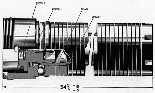
25. Upon removing the ram spring and tube assembly from the compressing tool, check its length against Figure 47. If it does not agree with the length shown, replace the unit in the compressing tool, lock it in place with the tool screw and nut and lengthen or decrease whichever is necessary by turning retainer plug (299930-1) in or out until the proper length is reached.
Figure 47-Correct length of ram spring and tube assembly (299928)-retainer plug inverted in safety position
26. RAM SPRING AND TUBE ASSEMBLY (299928) INSTALLATION-Pass retainer gasket (299930-3) over flange end of the assembly, the springs and thrust bearing, and against retainer
113
(299929-5). Raise the assembly with hoisting hook (299989-6) locked in place and lower it into the center of ram (299926-1). See Figure 48. Be sure retainer gasket (299930-3) is in place. For safety reasons do not try to screw ram spring retainer (299929-5) into its mating threads at this time.
27. CARRIAGE ASSEMBLY (299943) REASSEMBLING-Oil carriage lock plunger (299943-1) with extra light mineral oil, Navy Symbol 1042, 2110 or 2075 and insert the plunger into its hole in carriage (299944-1) and place plunger spring (299943-2) into its hole in the plunger. Force the spring down with cover (299943-3) until the cover is far enough down to force cover retainer (299943-4) into the groove in the plunger hole. See Main Section View, Plate 3.
If cradle lock plunger hole plug (OE-3514) was removed, install a new one by setting it in the hole in the carriage with the hollow side toward the inside and striking the center of the plug with drift (OE-1616) until a dimple is formed in the center of the plug. Assemble cradle lock plunger (299943-5) in carriage after oiling it with extra light mineral oil, Navy Symbol 1042, 2110 or 2075. The grooved end of the plunger should be entered into the hole first.
Install cradle lock lever (OE-3512) and two lock lever spacers (OE-3518) into their hole in the carriage and drive lock lever pivot pin (OE-3513) through the holes in the lever and spacers. See Section C-C, Plate 3. Stake the pin securely at both ends to prevent it from coming out.
Slide lock lever water seal (OE-35191 over the cradle lock lever and seat it in the grooves in the boss on the carriage and lock lever.
Place lock plunger ball (OE-3511) and spring (OE-3516) in their hole in the carriage and screw in retainer screw (OE-3517).
Screw trunnion bracket and pivot bearing pressure oiler (OE-2259) into its hole in the carriage.
Figure 48-Lowering ram spring and tube assembly into ram
28. CARRIAGE ASSEMBLY (299943)- INSTALLATION-Screw the two pilot screws (299989-4) into opposite holes in the top of the ram. Carefully clean the bottom side of the carriage and place it on top of the ram. Fasten the carriage to the ram with six carriage to ram screws (299946-1). Remove the two pilot screws and install the remaining two screws (299946-1). Tighten all screws to 75 foot pounds torque, using torque tension wrench (299991-2) and socket (299992-2). If the tension wrench is not available, tighten with a pull of 75 pounds on a wrench handle one foot long or 38 pounds on a handle two feet long.
29. CRADLE ASSEMBLY (299947)- REASSEMBLING-Assemble cheek plates (299947-1) right and (299947-2) left to cradle, using four attaching screws (OE-2263) in each plate. The end of each plate having an extension on it goes to the front.
114
Operation Number
Drive securing bolt locating pin (OE-2262) into securing pin (OE-2188) until it protrudes equally on both sides. Place securing bolt spring (OE-2189) on small end of bolt and insert the bolt and spring in the bolt hole in the cradle, after applying a coat of Anti-seize compound, Navy Specification 52-C-19 (Int.) on the bolt. Assemble withdrawing head (OE-2190) on the lower end of the bolt and secure it by driving in securing pin (OE-2261).
Place cocking sheave (299950-2) in slot in rear end of cradle and drive in sheave pin (299950-3). Secure pin in cradle by driving taper pin (12-Z-49-63) into the cradle from the top.
Screw cradle trunnion pin oiler (OE-2259) into its hole in the cradle.
30. CRADLE ASSEMBLY (299947)- INSTALLATION-Hold the cradle in the carriage with the gun securing bolt forward and the trunnion holes in the cradle and carriage in line. Drive trunnion pins (OE-2161) right and (OE-2160) left outwards so that they pass through the cradle and carriage. See Section A-A, Plate 3. Key (OE-2191) should be in place in trunnion pin (OE-2160) before driving the pin into place. Screw securing nut (OE-2162) onto pin (OE-2161), using wrench (OE-2904 and spanner (OE-3157). Lock the nut in place with securing pin (OE-2269). If the holes in the nut and pin do not line up when the nut is tight, back nut off until the holes do line up.
Slide spring housing cover (OE-2165) over carriage pin (OE-2160) and secure it to the carriage with four screws (OE-2256).
Build up cradle spiral spring and housing assembly (OE-2312) as follows: If bushing (OE-2166) was removed from housing (OE-2164) press in a new one. Place spiral spring (OE-2169) in housing so that the spring winds clockwise toward the center when looking into the housing. See Figure 49. Install spring securing bolt (OE-2168) and lock washer (OE-2278) in housing so that the stud end of the screw passes through the anchor hole in the outer end of the spring.
Figure 49-Correct position of spiral spring in housing
115
Operation Number
Raise the cradle to the 90 degree position and lock it in place by pulling out cradle lock lever (OE-3512). Slide the cradle spring and housing assembly onto the left trunnion pin with the radial portion of the spring sliding in the spring slot in the trunnion pin, until the notches in the housing are just clear of those on the housing cover.
NOTE-Keep hands clear of the serrations to prevent injury.
Turn the spring housing clockwise until spring tension is felt, then turn further in the same direction to the first place where the notches in the housing and cover will engage. Force the housing into engagement with the cover. Install spring housing trunnion pin nut (OE-2163) and tighten, using wrench (OE-2904). Lock the nut on the pin by driving securing pin (OE-2268) through nut and pin. If holes in the nut do not line up when the nut is tight, back nut off until the holes do line up.
NOTE-In order to improve the balance of the gun when installing the Mark 14 Mod. 2 sight on the rear end of the cradle, or when interchanging solid and ribbed gun barrels, the cradle spiral spring housing may be adjusted one or two notches from the standard setting. Cradle spiral spring spanner (367543-1), Figure 52, will be found helpful when making this adjustment.
31. SHIELD ASSEMBLIES (OE-2316) RIGHT AND (OE-2317) LEFT-Assemble shield plates (OE-2219) or (OE-2289 right and OE-2290 left) to shield brackets (OE-2220) right and (OE-2221) left, using four bolts (OE-2228) and nuts (OE-2229) in each plate.
Bolt the right and left shield assemblies to the carriage, using four bolts (OE-3535), lock washers (OE-2275), and nuts (OE-2217) on each bracket.
Bolt shield strap (299951-1) to the shield plates, using four bolts (OE-2227) and nuts (OE-2229).
32. RAM SPRING RETAINER (299929-5)-Engage the threads on the retainer with those on the inside of ram (299926-1), by turning the retainer with retainer wrench (299989-5) and retainer wrench handle (299990-1). Pull the retainer down tight so as to seal it on its gasket (299930-3).
33. CYLINDER SLEEVE (299925-1) -Lock the cradle in the 5 degree position. Oil cylinder sleeve packing (299925-3) and be sure it is free of wrinkles around its outer edge.
With carriage lock plunger (299943-1) engaged in one of the notches in the sleeve, screw the sleeve down on ram cylinder (299924-1) until it is tight, by turning the carriage in clockwise direction when viewed from the top.
34. RAM SPRING RETAINER PLUG (299930-1) -Carefully elevate the cradle to the 90 degree position and lock in place with lock lever (OE-3512). Unscrew the plug from retainer (299929-5) using retainer plug wrench (299990-3), 7/8" socket (299993-4), and swivel end wrench handle (299997-1). The engaging threads for this operation are left hand. Place retainer plug gasket (299930-2) in the retainer and install the retainer plug again but this time turn it over so that its short, large diameter end is threaded into spring retainer (299929-5). See Figure 50. The engaging threads for this operation are right hand. Tighten the plug to 125 foot pounds torque, using 7/8" socket (299993-4) and torque tension wrench (299991-2). If the tension wrench is not available, tighten with a pull of 125 pounds on a wrench handle one foot long or 62 pounds on a handle two feet long.
35. RAM AIR VENT VALVE ASSEMBLY (299930)-Screw the air vent valve assembly into the hole in retainer plug (299930-1) and pull down tight with 3/8" socket (299995-2) and crank type wrench handle (299996-1).
116
Figure 50-Retainer plug secured in retainer
Operation Number
36. FILLING HYDRAULIC SYSTEM-Pour 4 gallons, 2 quarts (31.4 pounds) of oil mixture (OE-3533) into the oil tank through the oil filler hole in the pedestal casing. The oil must be poured slowly as it has to flow through the strainer. After about 3 gallons have been poured in, pump each pedal about 5 times. Pour the balance of the oil mixture into the oil tank.
NOTE-Specifications for oil mixture (OE-3533). If necessary to prepare the specified oil mixture in the field, mix 3 gallons, 3.9 quarts (27.8 pounds) of extra light mineral oil, Navy Symbol 1042 with 2.8 quarts (4.9 pounds) of No. 1 fuel oil. Mix in a clean container and keep free of dirt and water. If larger or smaller amounts are needed, mix in the proportion of 85% of oil, Navy Symbol 1042 and 15% fuel oil, either by volume or weight.
37. BLEEDING-Raise carriage to its maximum height three times by pumping up once as fast as possible with each of the three pumps. Place bleeding pipes (299993-7 and 299992-4) over the end of base air vent valve (299942-2) through the hole in the pedestal casing, and place the other end in a suitable, clean container. Open the valve slightly and watch the oil flowing out of the hose. When the oil flows free of air bubbles, close the valve and remove the bleeding pipes. Pour the bled oil back into the tank.
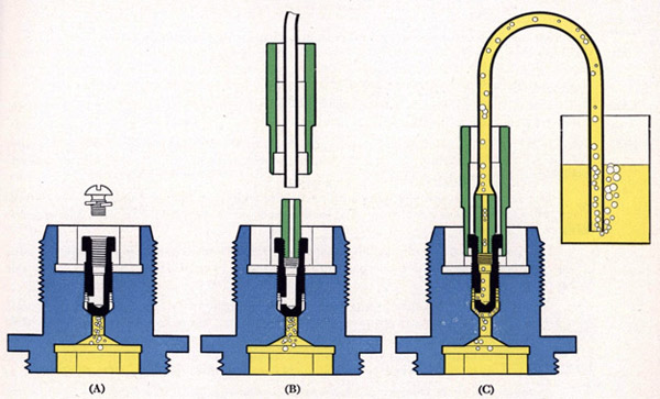
Remove ram air vent valve screw (12-Z-8-270) and lock washer (OE-1293), (A), Figure 51 and install in their place in air vent valve (299930-4) bleeder fitting (299992-3). Place bleeding pipes (299993-7 and 299992-4) on the fitting and slip 3/8" socket (299995-2) over the hose so that it can turn valve (299930-4), (B), Figure 51. Hold the free end in a suitable clean container, raise the carriage several inches by pumping one of the pedals, and open the valve slightly. See (C), Figure 51. Operate one pump slowly at least five strokes. Then operate the other two pumps in the same manner. Never bleed off more than one quart of oil at one time. When a quart is bled off, close the air vent valve and pour the bled oil back into the tank.
117
Figure 51-Bleeding ram air vent valve
Operation Number
Bleed the base air vent in the same manner as described before, pouring the bled oil back into the tank.
Bleed the ram air vent valve again in the same manner as before. When all bubbles stop coming out with the oil, check by lowering the carriage and stopping it before it goes all the way down. If it stops sharply, the air is probably all out of the system. If it stops, then bounces slightly, there is still air in the system and further bleeding is required.
When bleeding is completed, close the base air vent valve and the ram air vent valve tightly. Remove bleeder fitting (299992-3) and install lock washer (OE-1293) and screw (12-Z-8-270) in the valve and tighten securely.
Lower the carriage all the way and refill the tank until the oil level can be seen in the strainer. Insert oil tank filler cap gasket (299936-5) in filler hole and screw in filler cap (299936-4), tightening it securely with socket (299992-2) and swivel end wrench handle (299997-1).
38. RAM COVER (299946-2)-Remove any oil drippings from top of carriage and ram spring retainer by soaking it up with rag waste and install ram cover in hole in carriage.
39. WEIGHT AND BAND ASSEMBLY (OE-2207)-Assemble the weight and band assembly to the cradle cheek plates, using pivot bolt (OE-2177), nut (OE-2178), and cotter pin (OE-2230). See Section B-B, Plate 3.
40. CARTRIDGE BAG ASSEMBLY (OE-2198)-Place the cradle in the 5 degree position and lock it in place. Place weight and band in bag. Fasten bag to cradle and carriage, using two bolts (OE-2172), nuts (OE-2173), and cotter pins (OE-2231). The nuts should be left sufficiently loose so that the cartridge bag ends can rotate on the bolts.
118
Operation Number
41. CASING HOLE COVERS (299915-2)-Swing the hole covers into position and secure them with screws (12-Z-41-253). The three upper covers should have the elongated hole at the top, and the cover over the base air vent valve hole should have the elongated hole at the bottom.
42. CYLINDER SLEEVE SET SCREW (299925-2)- Install the four screws in the pedestal near the top, tightening them with Allen wrench (299993-2).
43. LUBRICATION-See lubrication chart, Figure 28. Raise the carriage about 6 inches and remove cylinder oil well plug (299923-7) from the top of the ram cylinder. Fill the well with oil mixture (OE-3533) and replace the plug.
Lubricate the six oilers on the pump assemblies with extra light mineral oil, Navy Symbol 1042, 2110 or 2075. Place a few drops of this oil on each of the bearing joints of the pump pedals and replace the covers.
Lubricate the two cradle trunnion pin oilers (OE-2259) with grease gun (OE-1637), using grease (OS-1350). Continue to pump gun until grease starts to come out of the joints on the side of the pins.
Apply a coat of Anti-seize compound, Navy Specification 52-C-19 (Int.) on gun securing bolt (OE-2188). Place several drops of extra light mineral oil, Navy Symbol 1042, 2110 or 2075 on cradle lock plunger (299943-5) and work the plunger in and out of the carriage several times. Place several drops of extra light mineral oil, Navy Symbol 1042, 2110 or 2075 in the cavity in the carriage on top of the carriage lock cover and allow it to seep down past the cover.
At all places where bearings are lubricated or oilers are filled, it is allowable to use extra light mineral oil, Navy Symbol 1042, 2110 or 2075 in place of oil mixture (OE-3533). IT IS NEVER ALLOWABLE TO PUT MINERAL OIL ALONE IN THE OIL TANK.
119
MOUNT TOOLS
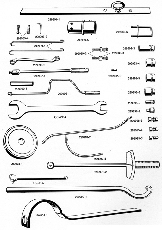
Figure 52-Mount Tools
120
TOOLS
Shipped with every Mark 6 Mount is a tool roll (299998) containing all the tools listed below and illustrated in Figure 52, except (299991-2) torque wrench-1/2" drive, (299991-1) ram hoisting bar, and (299993-1) ram oil seal installation pilot. These latter tools are included in the spare parts and tool box shipped to Shore Bases and Tender Ships.
These tools, used together with the tools shipped with every Gun as tool roll and contents (299817), are sufficiently complete to allow the complete stripping and reassembling of the gun mount, except the ram spring and tube assembly (299928). For this operation a special spring compressing tool (367539) is required. This tool is furnished only to Shore Bases. For this reason (299928) ram spring and tube assembly will be handled as a complete unit for Vessel and Tender service.
This same compressing tool can be used for stripping and reassembling equalizing spring and tube assembly (OE-2001) used on Mark 4 Mount. These tools are sufficient to completely strip and reassemble the Mark 6 Mount and no extra tools are needed except a bench vise and the gun mount hoisting hook (300003-1) which was shipped with the mount in its shipping box.
The use of all tools is covered in Stripping and Reassembling sections of this Pamphlet.
Tool Number
Tool Name
299991-1
Bar-Ram Hoisting
299992-3
Fitting-Ram Air Bleeder
299996-1
Wrench Handle-3/8" Drive Crank Type
299997-1
Wrench Handle-1/2" Drive Swivel End
299990-1
Handle-Ram Spring Retainer Wrench
299989-1
Hook-Pump Piston Rod Assembling
299989-6
Hoisting Hook-Ram Spring
299993-7
Pipe Assembly-Long-Bleeding
299992-4
Pipe Assembly-Short-Bleeding
299989-3
Nut-Pump Valve Chamber Cover Installation
299993-1
Pilot-Ram Oil Seal Installation
299995-2
Socket-3/8" Deep Type-3/8" Drive
299993-3
Socket-3/4" Deep Type-1/2" Drive
299995-3
Socket-1/2" Universal-3/8" Drive
299995-4
Socket-9/16" Universal-3/8" Drive
Tool Number
Tool Name
299995-5
Socket-5/8" Universal-3/8" Drive
299993-4
Socket-7/8" Standard-1/2" Drive
299993-5
Socket-15/16" Standard-1/2" Drive
299993-6
Socket-1" Standard-1/2" Drive
299992-2
Socket-3/8" Special Male-1/2" Drive
299989-2
Screw-Pump Valve Chamber Cover Installation
299993-2
Wrench-3/8" Allen Type
299996-2
Wrench-9/16" and 5/8" Box End
367543-1
Spanner-Cradle Spring Housing
OE-3157
Spanner-Trunnion Pin
OE-2904
Wrench-1", 14" and 2"-3/16" Open End
299990-3
Wrench-Ram Spring Retainer Plug
299989-5
Wrench-Ram Spring Retainer
299991-2
Wrench-Torque-1/2" Drive
299989-4
Screw-Ram Cylinder Installation
367539
Compressing Tool-Ram Spring and Tube Assembly
Plate 3
PLATE 3
General Arrangement of Mark 6
20 MM Antiaircraft Gun Mount
Between page 120 and 121 (Large size image.)