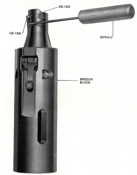
The breech face piece (OE-1305) can be removed from the breech block without removing the breech block from the gun mechanism. This operation is facilitated by the use of face piece removing tool (367516-3), see Figure 86.
On mounts with the cocking sheave, the breech block can be partially retracted by using the cocking sheave methods described on pages 122 and 125.
On Marks 4 and 6 mounts not equipped with the cocking sheave, the breech block can be partially retracted by elevating the carriage as described on page 125. By this method the column can be raised until the breech block has been drawn back five or six inches from the uncocked position.
On Mark 5 mounts without the cocking sheave lock the cradle in either the horizontal or vertical position. Attach one end of cocking rope (OE-2029) to the breech bolt cotter and draw the breech block back five or six inches from the uncocked position. Keep the breech block drawn back by winding the cocking rope across the back of the hand grips-around the right hand grips and back across the left hand grips. Repeat this winding until the rope is secured so that the breech block cannot move forward.
Release breech face piece securing spring (OE-1306) from locking notch in face piece by inserting tool (367516-3) through the openings in the left breech bar and breech casing and slide it between the spring and breech block. The pointed end of the tool can be engaged under the spring through a groove about 34 inch aft of the forward end of the breech block. See Figure 86.
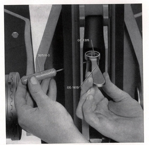
Slide the tool under the spring for about 1/2 inch. Then engage face piece spanner (OE-1619) on the breech face piece and turn to one side as far as possible, see Figure 87. Remove the spanner and continue to
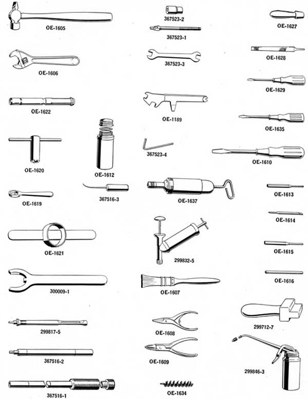
The following are the names of the gun tools in Figure 85.
OE-1605 8 Oz. Cross Peen Hammer
OE-1606 Adjustable Wrench
OE-1607 Brush
OE-1608 Pliers-External*
OE-1609 Pliers-Internal*
OE-1610 Screw Driver-Large-5-inch
OE-1612 Grease Container
OE-1613 Punch Small
OE-1614 Punch for Removing Hammer Plate
OE-1615 Punch Large
OE-1616 Drift
OE-1619 Breech Face Piece Spanner
OE-1620 Double Loading Stop Bushing Spanner
OE-1621 Barrel Spring Seating Ring Spanner
OE-1622 Cartridge Case Extractor Tool
OE-1627 File Handle
OE-1628 5-Inch File
OE-1629 Screw Driver-Small
OE-1634 Cleaning Rod Brush
367516-1 Cleaning Rod and Handle Assembly
367516-2 Cleaning Rod Ejector Assembly
299817-5 Cleaning Rod Rag and Brush End Assembly
OE-1635 Screw Driver-For Barrel Screw
OE-1637 Grease Gu or
299832-5 Grease Gun
299846-3 Oiler
300009-1 Barrel Removing Tool
OE-1189 Sight Universal Spanner
367523-1 Sight Socket Wrench Handle
367523-2 Sight Socket Wrench
367523-3 Sight Double Open End Wrench
367523-4 Sight Allen Type Wrench
299712-7 Magazine Loading Tool
367516-3 Breech Face Piece Removing Tool
*These pliers are not hardened and should be used only for the purposes intended.
132
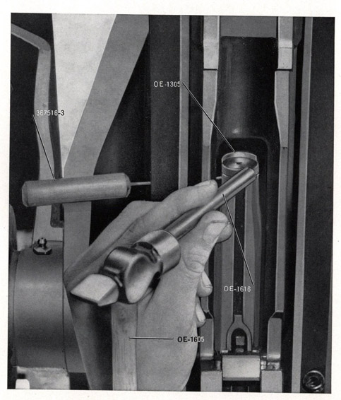
turn the face piece about 90° or 1/4 turn, using drift (OE-1616) and hammer (OE-1605).
Pull the face piece out of the breech bolt.
Figure 86-Tool (367516-3) inserted between breech block and securing spring
133
Figure 87-Turning face piece (OE-1305) with spanner (OE-1619)
134
INSTALLING FACE PIECE (OE-1305)
If the face piece tool was removed from the breech block, reinsert it between the securing spring and breech block. Place the face piece in the end of the breech block and tap it into place with the drift if necessary. Remove face piece tool (367516-3). Lock the face piece in the breech block by tapping it back into place with hammer (OE-1605) and drift (OE-1616) engaged in the groove in the face piece. Continue to turn the face piece until the ejector grooves in the face piece and breech block are in alignment. See Figure 88.
Check position of face piece to see that securing spring is locked in place by placing spanner (OE-1619) on the face piece and moving it from side to side. If there is no movement, the spring is properly engaged.
Figure 88-Tap face piece into place with drift (OE-1616)
135
PARTIAL STRIPPING-SUFFICIENT FOR ROUTINE CLEANING AND LUBRICATION
NOTE-These instructions should be read in conjunction with the general assembly drawing of the Gun, Plate 1 and the List of Parts, pages 163 to 213.
Each part mentioned in these instructions for stripping or reassembly is identified by its "OE" or part number, shown on the General Assembly Drawing, Plate 1 and in the List of Parts, pages 163 to 213.
The Parts list gives the "OE" or "Part" numbers and the corresponding "Item" number. "OE" and "Part" numbers identify Parts used on the Mark 4 Gun. "Item" numbers identify Parts used on the Mark 2 Gun.
Operation Number
1. UNLOCKING THE GUN
Remove the magazine. Uncock the gun mechanism by any of the methods described in Chapter 11. BE CAREFUL NEVER TO SLAM THE BREECH MASS ON AN EMPTY GUN.
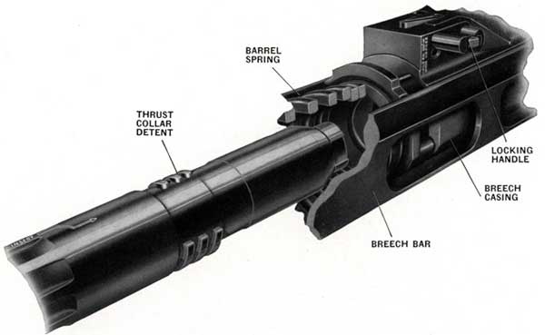
2. REMOVAL OF BARREL SPRING CASE AND COTTER SECURING BOLTS AND RETAINERS
(A) Gun mechanism removed from cradle
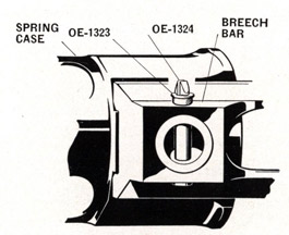
(a) Split type retainer (OE-1324), Figure 89
(1) Barrel spring case and cotter securing bolt retainers:
Press the upper ends of the retainers together and remove them from the bottom. Remove bolts from the top.
Figure 89-Split pin
type retainer (OE-1324)
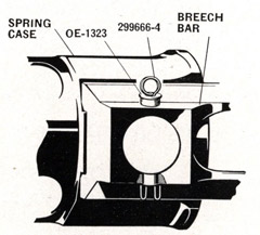
Figure 90-Round wire type retainer (299666-4)
136
Operation
Number
(b) Wire spring type retainers (299666-4), Figure 90
(1) Barrel spring case securing bolt retainers-spring case with hollow trunnions:
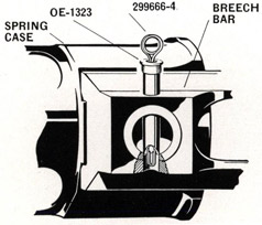
Press the free ends of the retainers together and push the retainers up slightly to hold the ends inside the hollow bolts. See Figure 91. Hold the bolts from moving up at the same time as care must be exercised to prevent the ends snapping into the hollow part of the trunnion when withdrawing the bolts and making their removal difficult. Remove the retainers and bolts together from the top.
(2) Barrel spring case and cotter securing bolt retainers-spring case with solid trunnions:
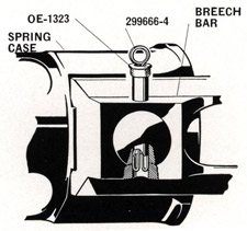
Press the free ends of the retainers together and withdraw the bolts and retainers together from the top. See Figure 92.
Figure 91-Draw free ends of
retainer up inside of bolt
Figure 92-Remove securing bolt
and retainer together
(B) Gun Mechanism Attached to Cradle
(a) Split type retainers (OE-1324)
(1) Barrel spring case securing bolt retainers:
Press the upper ends of the retainers, see Figure 89, together and remove them from the bottom. Remove bolts from the top.
(2) Cotter securing bolt retainers:
If the cradle has the elongated holes directly beneath the retainers, the retainers can be removed by pressing the upper ends together and pushing them down through the holes. Newer cradles have these holes in them. Accomplishment of Ordalt No. 1366 will provide the holes in cradles now in service.
137
Operation
Number
(b) Wire spring type retainers (299666-4), Figure 90
(1) Barrel spring case securing bolt retainers-spring case with hollow trunnions:
Remove the same as described in (A) (b) (1).
(2) Barrel spring case securing bolt retainers-spring case with solid trunnions:
Remove the same as described in (A) (b) (2).
(3) Cotter securing bolt retainers:
Grip the loop of the retainer and exert a light upward pull. Reach the first finger of one hand under the breech bar and press one end of the retainer toward the center of the hollow securing bolt while there is a slight upward pull on the loop of the retainer. The end of the retainer should be felt to jump up slightly and stay in position against the end of the securing bolt. If it does not stay in position, rotate the retainer one-half turn and press the opposite end of the retainer toward the center of the bolt. One end of the retainer is longer than the other and this long end should stay in position against the end of the bolt as long as there is an upward pull on the retainer. When the long end of the retainer is in position against the end of the bolt, continue to pull upward on the loop and at the same time rotate it one-half turn. Push the other free end of the retainer toward the center of the securing bolt and withdraw the two parts together from the top. Removal will be similar to that shown in Figure 92.
3. BARREL SPRING REMOVAL
Secure cradle in horizontal position. Remove right front and left rear securing bolt retainers (OE-1324 or 299666-4) and bolts (OE-1323) as described in Operation 2. Slide the right breech bar assembly (OE-1313) off the spring case (OE-1102 or OE-1105)* at the same time withdrawing breech bolt cotter (OE-1316) clear of the left breech bar assembly (OE-1312). Slide the assembly of spring case and left breech bar, barrel springs and spring sleeves off the muzzle end of the gun barrel.
Gun mechanism may have to be removed for this operation if the cradle does not have the elongated holes for the cotter securing bolts.
4. HAND GRIPS REMOVAL
Press the hand grip retaining catch and remove the hand grips by unscrewing counter-clockwise. The hand grips cannot be removed while the gun mechanism is mounted in the cradle unless the cradle is the new short type Mark 2 Mod. 2, Mark 4 Mod. 2 or Mark 5, or unless it has been shortened through the accomplishment of Ordalt No. 1366.
*On later model gun mechanisms a new welded type barrel spring case (OE-1105) is used in place of the former case (OE-1102) and barrel spring sleeve-front (OE-1318). In the new case the barrel spring sleeve-front is an integral part of the case and the separate front sleeve (OE-1318) is not used. See Figures 99 and 100.
5. TRIGGER PARTIAL STRIPPING
Slide the trigger cover plate (OE-1233) off to the rear. Pull out the trigger casing (OE-1202) to the rear complete with the trigger gear and trigger buffer springs (OE-1326). Remove the trigger buffer springs (OE-1326). Remove the trigger snap ring (OE-1238) using the special pliers in tool roll. Pull
138
Operation
Number
the assembled trigger hook holder (OE-1215) out to the rear. The trigger hook (OE-1216) on its axis bolt (OE-1217) and its spring (OE-1343) will be pulled out with the trigger hook holder.
NOTE-A strong pull is required.
Care should be exercised in removing the trigger hook holder snap ring (OE-1238), not to spread it too far. Casualties have resulted from failure of the snap ring during operation. This can often be attributed to weakening of the snap rings during removal or installation.
The pliers are not hardened and they should be used for no other purpose except that expressed.
Drive out the trigger hook axis bolt (OE-1217) and lift out the trigger hook (OE-1216) and its spring (OE-1343).
6. BREECH BLOCK, BOLT AND SEAR REMOVAL
Slide the breech block (OE-1304) and the breech bolt (OE-1315) out the rear of the breech casing. Remove the recoil sear axis bolt snap ring (OE-1346) with the special pliers in the tool roll. Drive out the recoil sear axis bolt (OE-1319) and lift out the sear (OE-1317) and its spring (OE-1341).
7. BREECH FACE PIECE REMOVAL
Insert breech face piece tool (367516-3) in the recess under the lip of the face piece securing spring (OE-1306) and bend the spring clear of the face piece. Turn the face piece 90 degrees, either way, with face piece spanner tool (OE-1619) and pull the face piece out.
8. STRIKER GEAR REMOVAL
Remove the hammer axis bolt (OE-1309) by turning it 180 degrees and pushing it out. The hammer (OE-1308) is free and can be lifted out. The striker pin (OE-1307) will then drop to the rear, out of the breech block.
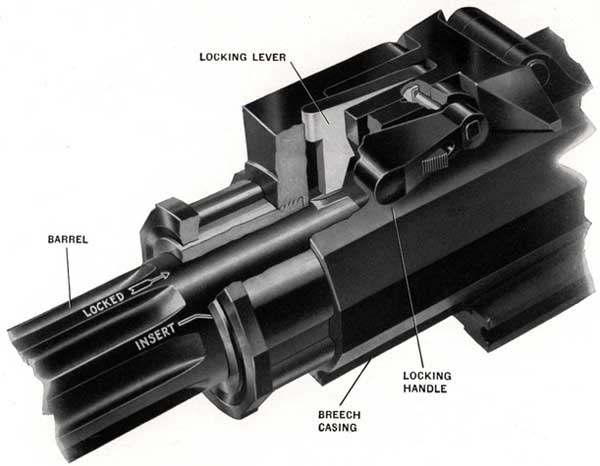
9. BARREL ASSEMBLY REMOVAL
Rotate the barrel locking handle (OE-1049) into the position marked "Unlock." Rotate the barrel counter-clockwise, looking from the muzzle to the breech, until stopped by the stop pin (approximately 60 degrees) and pull out to the front.
NOTE-The clearances between the gun barrel and its housing in the breech casing have to be very small and consequently the barrel may feel tight. A special tool (300009-1) is provided for rotating the barrel. Asbestos gloves are provided for the handling of hot gun barrels.
10. STRIPPING THE GUN BARREL ASSEMBLY
Remove the retaining pin (OE-1212) using screwdriver (OE-1635) from the tool roll. The double loading stop plunger can then be taken out.
11. STRIPPING THE BARREL LOCKING AND DOUBLE LOADING STOP GEARS
Drive out the barrel locking handle pin (OE-1265) using punch (OE-1613). Drive out the barrel locking lever axis bolt (OE-1079) from the left to the right, using special punch in tool roll. This will free the barrel locking handle (OE-1049) for removal. Lift out the double loading stop (OE-1054), together with its two plungers (OE-1071) and two springs (OE-1336). Lift out the barrel locking lever
139
Operation
Number
(OE-1078). Lift out the barrel locking lever plunger (OE-1070) and its spring (OE-1339). Remove the double loading stop axis bolt securing spring (OE-1346) with special pliers in the tool roll. Tap out double loading stop axis bolt (OE-1063). Use special punch in tool roll and tap from left to right. Lift out double loading stop lever (OE-1053) and its plunger (OE-1069) and its spring (OE-1344). Bend down the upturned lug on the double loading stop guide bushing locking washer (OE-1081). Unscrew the double loading stop guide bushing (OE-1055) with (OE-1620) spanner in tool roll. This will carry the double loading stop plunger upper (OE-1080) along with it. Lift out the locking washer (OE-1081).
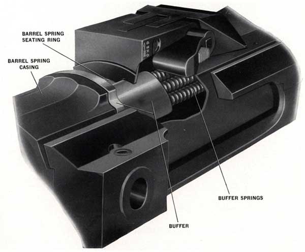
12. REMOVING THE BUFFER
Press in on the barrel spring seating ring retaining catch (OE-1058). Unscrew and remove the barrel spring seating ring (OE-1056) using (OE-1621) spanner.
NOTE-The barrel spring seating ring has a right hand thread. Pull the buffer (OE-1057) out to the front. Remove the twelve buffer springs (OE-1327).
Figure 93-Recoil Buffer Springs
140
Operation
Number
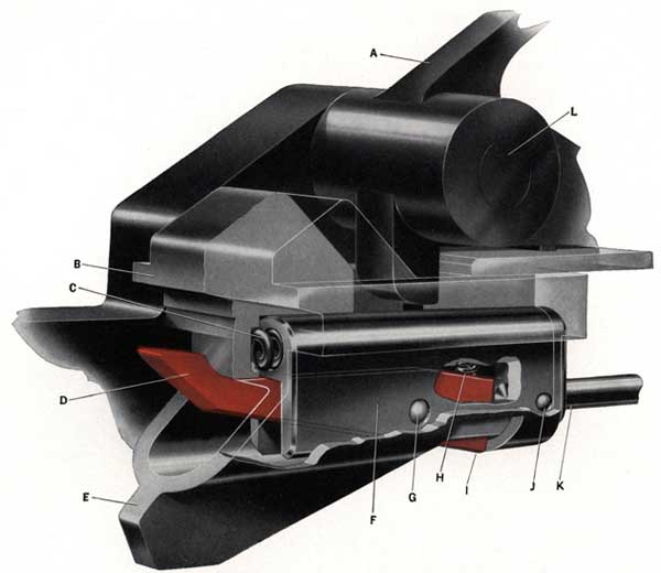
Figure 94-Magazine Interlock
A-Magazine catch lever (OE-1043)
B-Magazine securing lug on ejector
C-Interlock carrier spring (OE-1340)
D- Interlock lever (OE-1074)
E-Ejector (OE-1045)
F-Interlock carrier (OE-1066)
G-Axis bolt (OE-1067) holding interlock lever to interlock carrier
H-Magazine interlock lever spring (OE-1330)
I-Magazine interlock lever in catch recess in ejector
J -Axis pin (OE-1261) holding interlock rod to interlock carrier
K-Interlock rod (OE-1075)
L-Magazine catch lever spring axis bolt (OE-1076)
13. REMOVING THE EJECTOR AND MAGAZINE CATCH GEAR
Rotate the magazine catch lever (OE-1043) toward the muzzle so as to engage the catch. Press in the axis bolt securing spring (OE-1077) and drive out the axis bolt (OE-1035). Remove the magazine catch lever (OE-1043). Release the magazine interlock catch (OE-1046) by pressing down with
141
a suitable tool on the front ends of the catch. This releases the ejector (OE-1045). Slide out to the front the ejector (OE-1045) complete with the magazine interlock rod (OE-1075), interlock lever (OE-1074), interlock carrier (OE-1066), interlock lever spring (OE-1330), interlock carrier pin (OE-1261), interlock carrier axis bolt (OE-1067), interlock carrier spring (OE-1340).
NOTE-Two of the three springs (OE-1340) for the interlock catch and catch lever can be pulled out of the ejector for examination.
Remove the ejector from the interlock rod and carrier assembly by releasing the magazine interlock lever (OE-1074).
NOTE-The third spring (OE-1340) can then be pulled out of the carrier.
142
INSPECTION AND ADJUSTMENT AFTER PARTIAL STRIPPING
This completes partial stripping and next steps are:
1. Clean and oil the gun as instructed on page 108.
2. Inspect and adjust as follows:
The gun should be carefully examined, after partial stripping, for cracks in:
(a)-Buffer Springs
(d)-Hammer
(b)-Lip of the Breech Block Face Piece
(e)-Sear
(c)-Striker Pin
(f)-Trigger Hook
Examine all springs. Replace any that arc found weak, cracked, broken, bent, or distorted. Spares are supplied in the spare parts box for every spring.
Inspect all parts for burrs and remove with a fine file and smooth with a stone, if available.
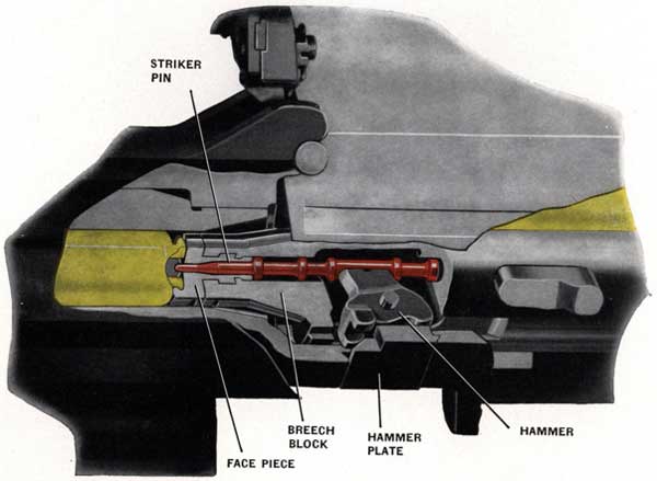
STRIKER PIN PROTRUSION
There is a tendency for the striker pin to "set up" after long use. See that the Striker Pin works freely in the Breech Block.
Figure 95-Examine Striker Pin After Extensive Use
143
REASSEMBLING A PARTIALLY STRIPPED GUN
The limits for protrusion, in service, are between 0.045 inch and 0.070 inch. This measurement is to be made with the striker pin pushed fully forward in the bolt.
NOTE-If the protrusion is too high, the point of the striker should be dressed back. If the protrusion is too low, there is no adjustment, and a spare striker pin should be installed.
CAUTION-Make certain that the striker pin hole in the breech block is free of burrs, dirt and corrosion.
Peening of the forward end of the striker pin hole in breech face piece (OE-1305) sometimes occurs and causes binding of the striker pin. When this happens, the face piece should be removed and the hole cleared out to its original size (".0992-".1004) using a No. 39 drill, or a new one installed.
HAMMER AND HAMMER PLATE WEAR
As previously stated, the striker pin reaches its full firing travel by momentum and not by a direct thrust all the way by the hammer, therefore, wear of the hammer and hammer plate is NOT important.
REASSEMBLING
Operation Number
1. MAGAZINE CATCH LEVER AND EJECTOR
Assemble the interlock rod (OE-1075) and the interlock lever (OE-1074) together with its spring (OE-1330), to the carrier (OE-1066). Insert one of the springs (OE-1340) into the interlock carrier. Slide the interlock carrier, complete with the interlock rod (as assembled above) into the ejector from the rear and push forward against the spring (OE-1340) until the carrier is held by the lever springing into the catch recess in the ejector. Insert the magazine interlock catch (OE-1046) into its recess in the breech casing. Insert the two remaining springs (OE-1340) and slide the ejector (as assembled above) into the breech casing from the front, taking care that the rod passes through its guide block (OE-1073). Hook the front toe of the magazine catch lever (OE-1043) into its recess in the ejector. Pull the lever and the ejector bodily backwards against the springs until the rear toe of the lever can be hooked behind the catch (OE-1046) and thereby hold the ejector temporarily in position. Then insert the magazine catch lever axis assembly (OE-1035) through the lever.
2. BARREL LOCKING GEAR AND DOUBLE LOADING STOP GEAR
Install double loading stop guide bushing locking washer (OE-1081). Install double loading stop guide bushing (OE-1055) using (OE-1620) spanner in the tool roll. Install double loading stop plunger upper (OE-1080). Install double loading stop spring case (OE-1069) and its spring (OE-1344) for the double loading stop lever. Install barrel locking lever plunger (OE-1070) and its spring (OE-1339). Install double loading stop lever (OE-1053), install its axis bolt (OE-1063) tapping it from right to left, install its securing spring (OE-1346) using special pliers in the tool roll. Install barrel locking lever (OE-1078). Install double loading stop (OE-1054) together with its two plungers (OE-1071) and two springs (OE-1336).
When installing a new double loading stop (OE-1054) it should be checked for proper clearances. Check should be made before installing double loading stop lever (OE-1053), barrel locking lever (OE-1078), and axis bolt (OE-1063).
When double loading stop (OE-1054) is pressed down at the rear so that the vertical faces contact breech casing (OE-1040) at (B), Figure 96, the clearance at (A) should be ".001 to ".005. This can be checked by inserting feeler stock between the stop and breech casing as shown.
144
Figure 96-Checking Operation of Double Loading Stop (OE-1054)
Operation
Number
If the clearance is greater than ".005, metal must be removed from the vertical stop faces of the double loading stop at (B). If the clearance is less than ".001, metal must be removed from the faces of the
double loading stop (OE-1054) at (A).
When clearance at (A) is correct the horns of the double loading stop should clear the top edges of breech bars (OE-1310 and OE-1311) by ".039 to ".059 at (C).
If double loading stop fails to hold the breech bars due to a fluttering condition, clearance should be checked as described above. If the clearance between the lower edges of the horns of the double loading stop is less than ".039 or in excess of ".059 with the proper clearance of ".001 to ".005 between the stop and breech casing faces, it indicates a bent stop. In this case the stop (OE-1054) should be replaced with a new one.
NOTE-To accomplish this, first insert the two sets of springs and plungers into the stop. Face toward the muzzle and hold these in place with the first fingers of each hand. Then insert the stop without letting the plungers come out.
Install the barrel locking lever axis bolt (OE-1079), tapping it from right to left. Install the barrel locking handle (OE-1049). Install the barrel locking handle pin (OE-1265).
3. REASSEMBLING THE BUFFER
Install the twelve buffer springs (OE-1327) in the breech casing. Install the buffer (OE-1057) from the front. Screw in the barrel spring seating ring (OE-1056) using (OE-1621) spanner from tool roll.
145
Operation
Number
Installing New Barrel Spring Seating Ring (OE-1056)
When installing a new barrel spring seating ring (OE-1056) it is necessary to grind a recess in the rear edge at the bottom for the seating ring retaining catch (OE-1058). Push up on catch (OE-1058) and screw the seating ring into place and tighten with spanner (OE-1621).
Mark location of retaining catch on seating ring with a scriber. Remove seating ring and grind the notch for retaining catch as marked. Reinstall the seating ring and tighten securely, using spanner (OE-1621).
NOTE-THE BARREL SPRING SEATING RING HAS A RIGHT HAND THREAD.
CAUTION-Hold the barrel spring seating ring retaining catch (OE-1058) inward while tightening this seating ring.
4. REASSEMBLING AND REPLACING THE BARREL
Lubricate double loading stop plunger lower (OE-1011) in Mark 4 barrel or (OE-1014) or (OE-1015 or OE-1016) in Mark 4 Mod. 1 barrel with extra light mineral oil, Navy Symbol 1042, 2110 or 2075 and insert it in the barrel. Lock this in place inserting the retaining pin (OE-1012) and tightening securely with the special screwdriver (OE-1635). Check to be certain the double loading stop plunger operates freely in the barrel. Place the barrel locking handle into the position marked "Unlock."
Insert the barrel with the "INSERT" arrow in line with the index mark on the front face of the barrel spring case. See Figure 97.
Figure 97-Barrel Installation
146
Figure 98-Gun Barrel Installed
When inserting the barrel, press down the horns of the double loading stop. This will prevent the double loading stop plunger in the breech casing from scoring the surface of the barrel.
NOTE-PUSH COMPLETELY IN.
Rotate the barrel clockwise, looking from the muzzle, until it is stopped by the barrel stop pin (approximately 60 degrees).
Place the barrel locking handle in the "LOCKED" position and then make certain that the barrel is locked against rotation by trying to turn it counterclockwise, looking from the muzzle.
5. STRIKER GEAR
Insert striker pin (OE-1307). Push it into the forward position and see that its slot is in line to receive the top portion of the hammer. Insert the hammer (OE-1308) into the slot in the striker pin. Insert the hammer axis bolt (OE-1309) in the hole in the hammer nearest the toes. Lock the axis bolt by rotating it 180 degrees so that it lies flush with the surface of the breech block.
147
6. BREECH BLOCK, BOLT AND SEAR
Place the sear spring (OE-1341) and sear (OE-1317) in position on the breech bolt and install the sear axis bolt (OE-1319). Install the sear axis bolt snap ring (OE-1346) using the pliers in tool roll. Install the breech bolt as assembled above in the breech block (OE-1304). Slide the two together into the breech casing and push into the forward position.
7. TRIGGER HOOK, CASING AND COVER PLATE
Place the trigger hook (OE-1216) and trigger hook spring (OE-1343), in position in the trigger hook holder (OE-1215). Install trigger hook axis bolt (OE-1217). Install the assembled trigger hook and holder from the rear into the trigger casing.
NOTE-A strong push is necessary when inserting the trigger hook into the trigger casing.
Install the trigger snap ring (OE-1238) using the special pliers in tool roll. Install the trigger buffer springs (OE-1326). Slide the trigger casing assembly (OE-1248) into the breech casing from the rear. Slide the trigger cover plate (OE-1233) on from the rear.
Care should be exercised when installing trigger snap ring (OE-1238), not to spread it too far. Casualties have resulted from failure of the snap ring during operation. This can often be attributed to weakening of the snap ring during removal or installation.
These pliers are not hardened and should be used for no other purpose except that expressed.
8. HAND GRIP REASSEMBLY
Screw on the hand grips. They should stop with the engraved number UP and with the hand grip catch engaged to prevent rotation.
NOTE-AT THIS POINT OF REASSEMBLY TEST THE OPERATION. Test the trigger gear, breech block and breech bolt for correct action by bringing the breech block and bolt, with the cotter (OE-1316) in place, to the rear and then pushing them forward again until they are held by the trigger gear. Trip the magazine interlock gear, press the trigger and see that the block and bolt are thereby fully released.
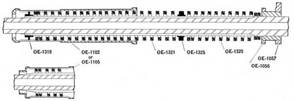
5. (a) BREECH BAR AND BARREL SPRINGS (Rectangular Wire)
Install the short barrel spring (OE-1320) to the rear. The smaller diameter end of the spring goes to the rear. Install the barrel spring center sleeve (OE-1325). Install the long barrel spring (OE-1321). Install the barrel spring front sleeve (OE-1318). This sleeve is not used when the welded type barrel spring case (OE-1105) is used. See Figure 99. Larger end of this sleeve goes toward the front. Slide the barrel spring case and left breech bar into place. While a helper is pushing backward on the spring case, slide front end of right breech bar over the barrel spring case trunnion and push the breech bolt cotter into the left breech bar. Insert the two cotter securing bolts (OE-1323) through the breech bars and cotter from the top. If the split type retainers (OE-1324) are used, they should be assembled through the bolts from the bottom. The two tongues of the retainers should be left athwart the gun. If left fore and aft, they will have a tendency to become disengaged on firing.
If the wire spring type retainers (299666-4) are used, they must be assembled from the top.
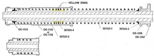
Place the rear barrel spring pilot (367534-3) on the gun barrel with its flat face to the rear. Place the long barrel spring (367533-1) over the gun barrel with the yellow painted end of the spring forward. Place the flat center spacer (367534-4) on the barrel. Place the short barrel spring (367533-2) on the gun barrel with its yellow painted end aft. If the barrel spring case is the forged type (OE-1102) place spring front sleeve (OE-1318) on the gun barrel with the large diameter end forward. Follow this with the spring case.
NOTE-Some guns use the welded type spring case (OE-1105), see Figure 100. In this case the front sleeve is not used.
Slide the barrel spring case and left breech bar into place. Slide front end of right breech bar over the barrel spring case trunnion while a helper is pushing backward on the spring case. Push the breech bolt cotter into the left breech bar. Assemble the breech bar securing bolts and retainers as instructed in Operation 9 (a).
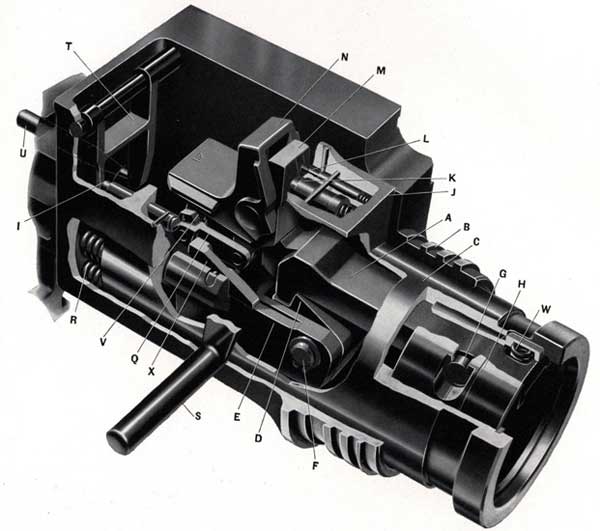
L- Parallelogram lever plunger-top (OE-1213)
M-Parallelogram lever-rear (OE-1203)
N-Parallelogram lever-top (OE-1204)
Q-Parallelogram levers-bottom (OE-1206)
R-Trigger buffer springs (OE-1326)
S-Trigger (OE-1220)
T-Magazine interlock fork (OE-1230)
U-Magazine interlock rod (OE-1075)
V-Parallelogram lever-front (OE-1205)
W-Trigger hook spring (OE-1343)
X-Breech Pawl (OE-1104)
152
In case of damage to, or failure of, the smaller parts, further stripping may be necessary.
A number of these operations are independent of any other and care should be taken not to disassemble further than necessary, as for instance:
EXAMPLE-The barrel is not the first operation on the list for Partial Stripping, yet it may be removed normally without taking off any other part.
The complete stripping instructions given below are a continuation of the Partial Stripping given on pages 135 to 141.
Operation
Number
1. TRIGGER CASING GEAR
Under Partial Stripping the following were removed: See page 137.
Trigger Cover Plate
Trigger Casing Complete
Trigger Buffer Spring
Trigger Hook and Holder
Drive out the parallelogram lever axis bolt-rear top (OE-1210) in either direction. Remove the trigger parallelogram complete. Remove the parallelogram spring box (OE-1211) by driving out its axis bolt (OE-1214) in either direction. A special punch is in the tool roll.
2. PARALLELOGRAM
Remove the two retaining pins (OE-1256) from the parallelogram lever axis bolt-bottom, front. Remove the spacing sleeve pin (OE-1272), and lever axis bolt, top front sleeve (OR-1208). Drive out the parallelogram lever axis bolt-top front (OE-1207). Drive out the parallelogram lever axis bolt-bottom front (OE-1209).
NOTE-Special punches are in the tool roll.
3. PARALLELOGRAM SPRING BOX
Drive out the two vertical pins (OE-1266) that are used to secure the two outer plungers (OE-1213). Remove the horizontal pin (OE-1268) that is used to secure the central plunger (OE-1212).
NOTE-There are two parallelogram lever plungers-top (OE-1213) and there is one parallelogram lever plunger-rear (OE-1212) that can be pulled out with their two springs (OE-1334) and one spring (OE-1342).
4. TRIGGER GEAR IN BREECH CASING
Drive out the trigger pin (OE-1265) in the hub of the trigger using special punch in tool roll. Tap out the trigger retaining bolt (OE-1221) inward using special punch in tool roll. Lift out the trigger (OE-1220). Tap out the trigger crank (OE-1223) inward using special punch in tool roll. Lift out the trigger pawl (OE-1222) and the pawl holder (OE-1219) together.
NOTE-The pawl can be separated from the pawl holder by driving out the pawl axis pin (OE-1231) from left to right.
Lift out the trigger intermediate lever (OE-1218).
153
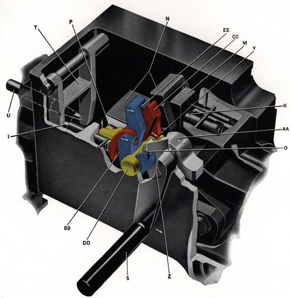
Figure 102-Trigger Action on Parallelogram
AA-Trigger intermediate lever (OE-1218)
BB-Trigger pawl holder (OE-1219) shown in BLUE
CC-Trigger pawl (OE-1222) shown in RED
DD-Trigger crank (OE-1223) shown in YELLOW
EE-Trigger pawl spring (OE-1332)
M-Parallelogram rear lever
N-Parallelogram top lever
Q-Parallelogram bottom levers
V-Parallelogram front lever
O-Point of contact between trigger intermediate lever and trigger pawl holder
P-Point of contact between trigger crank toe and parallelogram top lever
S-Trigger (OE-1220)
T-Magazine interlock fork (OE-1230)
U-Magazine interlock rod (OE-1075)
Y-Point of contact between trigger pawl and trigger crank
Z-Trigger retaining bolt (OE-1212)
154
Operation
Number
5. SAFE/FIRE GEAR
Drive out, from left to right, the safety gear axis bolt pin (OE-1262). This pin secures the safe/fire lever (OE-1237) to the axis bolt (OE-1234). Drive out the safety gear axis bolt (OE-1234).
NOTE-This frees the Safe/Fire lever (OE-1237) and the safety cam (OE-1236).
6. MAGAZINE CATCH AND INTERLOCK GEAR
Follow operation 6, page 138 of "Partial Stripping" necessary for examination of the sear for fractures. Remove the magazine interlock lever (OE-1074) from the carrier by driving out its axis bolt (OE-1067).
NOTE-This also releases the magazine interlock lever spring (OE-1330).
Lift out the interlock catch (OE-1046). Remove the magazine interlock fork (OE-1230) by driving out its axis bolt (OE-1224) in either direction.
7. TRIGGER PAWL TRIPPING BOLT
Drive out the trigger pawl tripping bolt spring case retaining pin (OE-1263). This pin secures the spring case (OE-1226) to the breech casing. Remove the spring case (OE-1226) complete with the trigger pawl tripping bolt (OE-1225) and its spring (OE-1338). The trigger pawl tripping bolt and its spring can then be removed from the spring case by driving out the trigger pawl tripping bolt retaining pin (OE-1255) transversely through the spring case.
8. MAGAZINE INTERLOCK ROD GUIDE BLOCK
Drive out the interlock rod guide block retaining pin (OE-1267) and press the block (OE-1073) out from the breech casing (OE-1040).
9. BREECH PAWLS
Remove the breech pawls (OE-1103 Right and OE-1104 Left) by prying out the right and left axis pins (OE-1322). The breech pawls and their springs (OE-1329) will then fall out.
10. HAMMER PLATE
Lift the end of the hammer plate securing spring (OE-1064) clear of the hammer plate (OE-1060) and tap the hammer plate upward to remove.
11. HAND GRIPS RETAINING CATCH
Drive out the retaining catch axis bolt (OE-1068) and lift out the retaining catch (OE-1062). Drive out the retaining catch plunger pin (OE-1258) and remove its spring (OE-1335) and the retaining catch plunger (OE-1065).
12. BARREL SPRING SEATING RING RETAINING CATCH
Drive out in either direction the barrel spring seating ring retaining catch retaining pin (OE-1269). Lift out the retaining catch (OE-1058) and its spring (OE-1337).
155
Operation
Number
13. BREECH CASING BARREL STOP PIN
Press in the breech casing barrel stop pin plate pin (OE-1072) using a pointed tool from tool roll. Drive out, in either direction, the barrel stop pin plate (OE-1059). Lift out the barrel stop pin (OE-1052), the barrel stop pin plate pin (OE-1072) and the barrel stop pin plate spring (OE-1331).
14. TRIGGER INTERMEDIATE LEVER PLUNGER ASSEMBLY
Push the trigger intermediate lever spring case (OE-1227) out by pushing on its rear end at the rear face of the breech casing. Remove the trigger intermediate lever spring case distance piece (OE-1228). Drive out the trigger intermediate lever plunger retaining pin (OE-1257). Lift out the trigger intermediate lever plunger (OE-1229) and its spring (OE-1333).
156
GUN COMPLETE REASSEMBLY
The complete reassembly instructions given below are a continuation of the "Reassembling a Partially Stripped Gun" on Pages 143 to 148.
Operation
Number
1. TRIGGER INTERMEDIATE LEVER PLUNGER
Place the trigger intermediate lever plunger (OE-1229) and its spring (OE-1333) in the trigger intermediate lever spring case (OE-1227). Install the trigger intermediate lever plunger retaining pin (OE-1257). Install the trigger intermediate lever spring case distance piece (OE-1228). Push the rear end of the trigger intermediate lever spring case (OE-1227) into the rear face of the breech casing.
2. BARREL STOP PIN IN THE BREECH CASING
Install the barrel stop pin plate spring (OE-1331), the barrel stop pin plate pin (OE-1072) and the barrel stop pin (OE-1052). Drive in, from either direction, the barrel stop pin plate (OE-1059).
3. BARREL SPRING SEATING RING RETAINING CATCH
Install in the breech casing the retaining catch (OE-1058) and its spring (OE-1337). Drive in, from either direction, the barrel spring seating ring retaining catch retaining pin (OE-1269).
4. HAND GRIPS RETAINING CATCH
Install in the retaining catch (OE-1062) the retaining catch plunger (OE-1065), its spring (OE-1335) and drive in the retaining catch plunger pin (OE-1258). Install the retaining catch (OE-1062) in the breech casing and drive in the retaining catch axis bolt (OE-1068).
5. HAMMER PLATE
Tap the hammer plate (OE-1060) downward into its recess in the breech casing. Make certain the hammer plate securing spring is in place.
6. BREECH PAWLS
Install the breech pawl springs (OE-1329) in the breech casing. Install the right breech pawl (OE-1103) and left breech pawl (OE-1104) on their springs, installed above. Install the breech pawl axis pins (OE-1322).
7. MAGAZINE INTERLOCK ROD GUIDE BLOCK
Press the magazine interlock rod guide block (OE-1073) in place in the breech casing (OE-1040) and drive in the interlock rod guide block retaining pin (OE-1267).
8. TRIGGER PAWL TRIPPING BOLT
Install the trigger pawl tripping bolt spring and the bolt in place in the trigger pawl tripping bolt spring case (OE-1226). Drive the trigger pawl tripping bolt retaining pin (OE-1255) transversely through the spring case. Place the spring case (as just assembled) and the trigger pawl tripping bolt spring (OE-1338) and tripping bolt (OE-1225) in the breech casing. Drive in the trigger pawl tripping bolt spring case retaining pin (OE-1263). This pin secures the spring case to the breech casing.
9. MAGAZINE INTERLOCK FORK
Reassemble the magazine interlock fork (OE-1230) to the breech casing by inserting the fork in its position and drive in its axis bolt (OE-1224) from either direction.
157
Operation
Number
10. SAFE/FIRE GEAR
Install the safe/fire lever (OE-1237) and the safety cam (OE-1236) and drive in the axis bolt (OE-1234). Install the safe/fire lever (OE-1237) on its axis bolt and drive the axis bolt pin (OE-1262) in from right to left. This pin secures the safe/fire lever (OE-1237) to the axis bolt (OE-1234).
11. TRIGGER PAWL, PAWL HOLDER, TRIGGER CRANK
Assemble the trigger pawl (OE-1222) and its spring (OE-1332) to the pawl holder (OE-1219) by inserting the pawl axis pin (OE-1231) from right to left. Drop this trigger pawl and holder assembly (OE-1246) into its position in the breech casing. Insert the trigger crank (OE-1223) from inside of the breech casing.
NOTE-The pawl, pawl holder, and trigger crank are all stamped with the letter "L" and when correctly assembled, all three letters must be visible from above. IF NOT VISIBLE, THE ASSEMBLING HAS BEEN INCORRECTLY DONE.
12. TRIGGER INTERMEDIATE LEVER
Insert the trigger intermediate lever (OE-1218) so as to engage the pin on the pawl holder.
13. TRIGGER AND TRIGGER HOOK
Reassemble the trigger (OE-1220) and trigger retaining bolt (OE-1221) from inside the breech casing. Install the trigger pin (OE-1265). Reassemble the trigger hook (OE-1216) and its spring (OE-1343) in the trigger holder (OE-1215) and drive in the trigger hook axis bolt (OE-1217).
14. PARALLELOGRAM
Place the two outer plungers [parallelogram lever plunger-top, (OE-1213)] and place the central plunger [parallelogram lever plunger-rear, (OE-1212)] and their three springs (2 of OE-1334 for OE-1213) and (1 of OE-1342 for OE-1212) in the parallelogram spring box (OE-1211). Install the horizontal pin (OE-1268) that is used to secure the central plunger (OE-1212). Install the two vertical pins (OE-1266) that are used to secure the two outer plungers (OE-1213). Reassemble the parallelogram. Install the parallelogram lever axis bolt, bottom front (OE-1209). Install the parallelogram lever axis bolt, top front (OE-1207)*. Install the parallelogram lever axis bolt, top front sleeve (OE-1208)* and the sleeve pin (OE-1272)*. Install the two retaining pins (OE-1256) on the lever axis bolt, bottom front.
NOTE-The parallelogram levers are all marked "L" and "R." A correctly assembled parallelogram will have all of the letters "L" visible and on the left side, and all of the letters "R" visible and on the right side. The parallelogram top lever is marked with the word "UP" and this must be visible from above.
Install the parallelogram spring box assembled above and drive in its axis bolt (OE-1214). Drive from either direction. Place the parallelogram assembled above in the trigger casing pushing it rearward against the spring plungers in the spring box in order to get the holes in line for the lever axis bolt rear top (OE-1210). A strong push is required. Drive this lever axis bolt (OE-1210) in from either direction.
*In later production a new parallelogram assembly (OE-1200) is used in place of the original assembly (OE-1240). This change involves the use of a new style parallelogram lever axis bolt-top (OE-1201) in place of axis bolt-top front (OE-1207) and bolt sleeve (OE-1208).
158
Operation
Number
When servicing the earlier type parallelogram assembly, and bolt (OE-1207) and sleeve (OE-1208) are found to be in need of replacement, the new type bolt (OE-1201) alone can be used. The head of the bolt MUST be installed on the right side.
15. TRIGGER HOOK HOLDER AND BUFFER SPRING
Install the trigger hook holder assembled in Operation 13, into the rear of trigger casing. A strong push is required. Replace the trigger snap ring (OE-1238) that secures the trigger hook holder in the trigger casing, using the special pliers in the tool roll. Replace the trigger buffer springs (OE-1326).
16. Complete the reassembly by following the instructions for reassembly, operations 1 through 9 inclusive. given in detail on "Reassembling a Partially Stripped Gun," Pages 143 to 148.