The cleaning and oiling of the gun should be carried out as required and when required and not at any fixed interval.
It should be realized that in this type of gun the force of explosion is absorbed in checking and reversing the forward movement of a relatively heavy bolt that is never locked. The proper functioning of the gun depends on the free movement of the recoiling parts and on the free operation of the various springs used.
Any dirt, corrosion or lack of lubrication that is present to a degree that will impede free movement and free operation will cause stoppages during firing.
CLEAN AND OIL
(A) As soon as possible after firing.
(B) If the gun gets wet.
(C) If the gun gets dirty.
(D) If there is any reason to expect corrosion to start.
In order to properly clean and oil the gun it is necessary to first partly disassemble. Instructions for Partial Stripping are given on Page 135.
LUBRICATING OIL TO BE USED
Use Medium Mineral Oil, Navy Symbol 1065 or 3065.
CAUTION-Do not add white lead, black lead, red lead or make any addition of any similar substance to the oil.
DOUBLE LOADING STOP PARTS LUBRICATION
The Double Loading Stop Plunger, Upper (OE-1080), Figure 78, and the Double Loading Stop Plunger, Lower (OE-1011 or OE-1014) in the barrel tend to become stuck with oil that is gummed by the heat of the gun. These parts should be cleaned periodically and lubricated with extra light mineral oil, Navy Symbol 1042, 2110 or 2075.
To remove the Double Loading Stop Plunger, lower (OE-1011 or OE-1014) from the barrel take out the retaining pin (OE-1012) using the special screw driver (OE-1635) in the tool roll. The plunger can then be taken out for cleaning and lubrication.
CAUTION-If the parts of the double loading stop gear become gummed or corroded, the stop plunger, lower, might not be operated, resulting in stoppage.
DOUBLE LOADING STOP GEAR AND BUFFER CORROSION
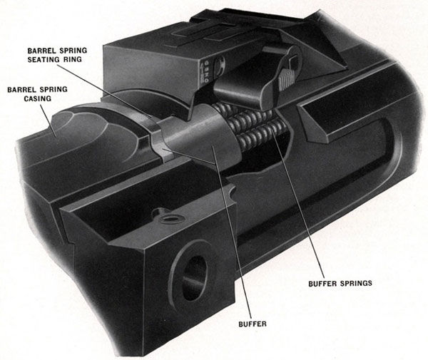
The parts of the double loading stop gear as shown in Figure 78 and also the buffer (OE-1057), Figure 80, are exposed to salt water corrosion and, therefore, require particular care in maintenance. See "Caution" note above.
SECURING BOLT LUBRICATION
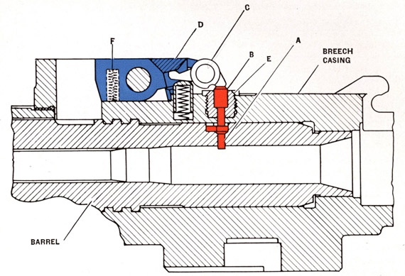
When the gun is being mounted in the cradle, the inside of the securing bolt hole, the breech casing and the securing bolt itself, see Figure 13, should be thoroughly coated with Anti-seize compound, Navy Specification 52-C-19 (Int.) for protection against corrosion.
The outside of the gun barrel and the outer and inner surfaces of the barrel springs should be coated with lubricating graphite, Navy Specification 14-G-5.
NOTE-Oil should not be used on the outside of the gun barrel nor on the barrel springs as it smokes when the barrel gets hot and the smoke will interfere with the sighting of the gun.
GUN BARREL BORE AND FIRING CHAMBER, CARE OF:
The bore and firing chamber should be lightly cleaned out IMMEDIATELY AFTER FIRING, using the cleaning rod equipment (299817-5, 367516-1, and 367516-2). See Pages 130 and 131.
Place a light coat of medium mineral oil, Navy Symbol 1065 or 3065, in the bore and firing chamber.
CAUTION-Do not fire with a heavily GREASED bore or firing chamber.
The proper functioning of the gun requires easy and regular extraction of the empty cartridge case, when it is blown backward by the firing chamber gases. Care must be taken, therefore, to maintain the firing chamber walls in good condition, thereby avoiding any unnecessary friction with the walls of the cartridge case. The firing chamber walls have a high lapped polish when the barrel is issued. FIRING CHAMBER WALLS MUST NEVER BE CLEANED WITH EMERY PAPER.
110
MUZZLE COVERS
The muzzle cover should be kept on the gun barrel muzzle to prevent water or dirt from getting into the bore. It should be removed before firing, whenever practicable. It is imperative that any coating of ice one inch thick or more be removed before firing an explosive projectile. Blind loaded projectiles, two of which should be loaded last in each magazine, may be safely fired through any ice coating when necessary.
STOPPAGES
If the gun stops of its own accord for any reason other than an empty magazine, the following immediate action should be carried out:
1. Put the safety catch to "SAFE" and note whether the recoiling parts are in the forward position. If the recoiling parts are in the forward position, a misfire, a broken striker, a broken hammer, or failure to feed from the magazine, is indicated. Safety precautions for a misfire should be observed.
2. Examine the double loading stop. If the horns are in the down or operating position, there is a round or part of a broken case in the chamber. If the portion of the torn cartridge case left in the chamber is forward of the stop, the double loading stop will not operate and a jam will occur. See "Use of Cartridge Extracting Tool" below.
3. If the magazine is empty and the gun stops in the forward position, it may be due to sticking or sluggish action of the magazine cartridge feeder bolt which trips the interlock lever. If examination shows that this bolt does not work freely, the magazine should not be used again until the condition has been corrected.
4. Remove the magazine and recock the gun. If the magazine is difficult to remove, it will come off as the breech block is withdrawn when cocking the gun. In the event of it being impossible to remove the magazine without recocking, care should be taken to cock the gun in one continuous movement and on no account must the breech block be allowed to go forward.
5. Examine chamber and the breech face piece. If the lip of the breech face piece is broken off, a new one must be installed.
6. CLEARING OF LOADED AND FUZED PROJECTILES FROM HOT GUNS.
For information on this subject, see the latest Bureau of Ordnance safety regulations, which at the date of issue of this pamphlet, are contained in Bureau of Ordnance Circular Letter No. G15-42, dated October 19, 1942.
7. Stoppages of the gun have occurred which appeared to have been caused by the presence of hair from ammunition packing material getting into the mechanism. Steps have been taken to eliminate this type of packing, but a large amount of ammunition has already been issued. At the first opportunity, and in any event before loading it into the magazine drums, ammunition should be examined to see that it is free of hair; and if hair or dirt is found, it should be removed. If grease is removed in this process, it must be replaced.
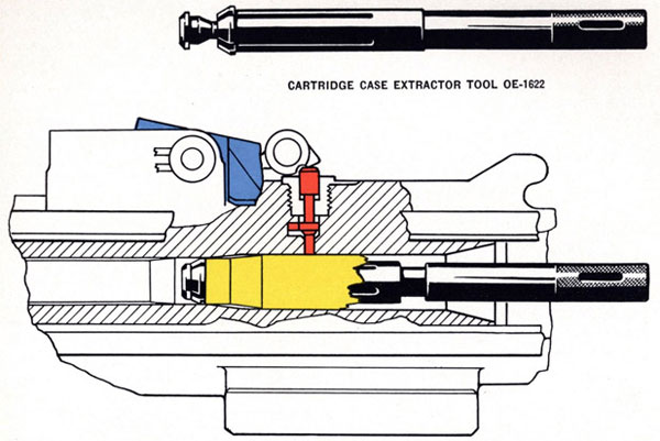
USE OF CARTRIDGE EXTRACTING TOOL
In case a torn cartridge case is left in the firing chamber it is necessary to use the extracting tool (OE-1622), Figure 79, to remove it.
The slotted sliding sleeve should be pulled back against the shoulder of the tool and the extracting tool inserted through the torn case. The sliding sleeve at its slotted end will be slightly compressed inside the torn case and as soon as the sleeve has been pushed through the case the flanged end will expand and rest against the end of the case as shown in Figure 79.
Pull back on the extracting tool or on a bar inserted through the handle of the tool. The sleeve will be forced onto the wedge piece preventing it from collapsing and permitting the torn case to be pulled out with the tool.
111
Figure 79-Using special tool OE-1622 to clear the barrel when
portion of torn cartridge case is left in firing chamber
LIFE OF THE GUN BARREL
The amount of life that a gun barrel will give depends on how hot the barrel becomes during firing.
Five magazines, containing sixty rounds each, or a total of three hundred rounds can be fired continuously without harm to the gun barrel.
Nine magazines, of sixty rounds each, or a total of five hundred and forty rounds, will cause serious wear if fired continuously.
If short pauses occur between the firing of each magazine, the wear will remain small, even after several thousand rounds.
During any prolonged firing, keep the gun barrel as cool as possible, either by frequent changes with the spare barrel, or by dousing the gun barrel with water.
The bore erosion gauge assembly (367548), which is to be issued to the service, should be used after approximately each thousand rounds of firing or less. Measurements taken with this gauge, in accordance with instructions to be issued with it, will indicate when the bore wear is so great that the gun barrel should be removed from service. When a gun barrel becomes too worn, recoil is shortened so that stoppages and failures to latch back will occur.
112
The bore plug gauge assembly (245760), [or (299881-3) which is used with (367516-1) cleaning rod and handle assembly], which is slightly larger than the bourrelet of a projectile, should be passed through the bore occasionally to assure that no constrictions are present. If the gauge will not pass, the gun barrel should be lapped out.
GUN BARREL REPLACEMENT
The gun barrel can be easily removed and a new one installed without stripping of any other parts.
NOTE-As the clearance between the gun barrel and the breech housing must be necessarily close, the barrel may feel tight, particularly when it is hot. A special removing tool (300009-1) and asbestos gloves are provided for this reason.
GUN BARREL REMOVAL
Remove the barrel by rotating the barrel locking handle to the position marked "Unlock."
Engage the tongue of the barrel removing tool (300009-1) in the wrench slot or rib groove (depending upon whether the gun barrel is solid or ribbed), rotate it 60 degrees counter-clockwise (looking from the muzzle to the breech) and, using the asbestos gloves if necessary, pull the barrel out of the breech casing.
NOTE: A new tool is under development to facilitate the removal of gun barrels. In addition to rotating the barrel, the tool can also be used to pull the gun barrel out of the breech casing.
As soon as the tool is approved, an Ordalt will be issued to cover alterations necessary to permit its use with gun barrels now in service.
GUN BARREL INSTALLATION
Align the arrow marked "Insert" on the gun barrel with the index mark on the front face of the barrel spring case. Push the barrel into the breech casing until it bottoms. Then rotate the gun barrel 60 degrees clockwise (looking toward the breech) or until the arrow marked "Locked" is in line with the index mark on the front face of the barrel spring case. While moving the gun barrel into position, press down on the horns of the double loading stop (OE-1054). This will prevent the stop plunger in the breech casing from scoring the surface of the gun barrel. Move the locking handle into the position marked "Locked."
VIOLENT RECOILS
If violent recoils, causing metal to metal contact of the buffer against the breech casing occur habitually, and more than one lot of ammunition has been used during these metal to metal recoils, then the cause is probably a collapse of the barrel springs and not a result of ammunition loading.
A metal to metal contact always occurs between the barrel spring casing and the buffer during the last inch of recoil. However, the buffer should not normally strike the breech casing. Weak barrel springs will cause the buffer springs to be overloaded and result in metal to metal contact of the buffer against the breech casing.
A remedy is to change to the spare barrel springs. If spare barrel springs are not available then insert flat washers at the rear end of the barrel spring up to a maximum thickness of three fourths of an inch.
113
CAUTION-Whenever possible, keep the gun UNCOCKED in order to relieve the spring tension and prevent the possibility of a permanent set of the springs.
BUFFER CORROSION
If the buffer (OE-1057), Figure 80, becomes corroded it may not have the free movement necessary to transmit the last of the recoil shock to the buffer springs and the free movement necessary to assist the barrel springs on counterrecoil.
Figure 80-Recoil buffer springs
114
USE OF 20 mm. GUN ON SUBMARINES
Because of the conditions under which the gun is used there are new problems involved in the maintenance and lubrication of this unit. Additional care is necessary to assure efficient operation upon surfacing and to provide adequate protection to the parts while submerged.
Proper cleaning is highly essential. After firing, all parts must be cleaned and traces of rust and corrosion removed by rubbing with Diesel fuel oil. All parts must then be adequately lubricated. Due to different finishes on the parts, and in view of their peculiar operating conditions, different types of lubricants are required. The detailed instructions are as follows:
CLEANING
Strip the gun completely (see Gun Complete Stripping and Reassembly, Pages 151 to 158). A mixture of oil, water, and powder residue will be found on the internal parts of the gun. Wash all parts with Diesel fuel oil. Examine them carefully and remove all traces of rust and corrosion by rubbing with a cloth saturated with Diesel fuel oil. Then pass dry patches through the bore until thoroughly clean. All other parts should be blown dry with compressed air. Particular attention should be given to cleaning the gun barrel, barrel springs and sleeves, spring case, buffer, buffer springs and barrel spring seating ring to remove all traces of rust. Do not use an abrasive, such as emery cloth.
LUBRICATION
Wipe all parkerized (black) parts except gun barrel, barrel springs and sleeves, spring case, buffer, buffer springs, and barrel spring seating ring with a cloth saturated with extra light mineral oil, Navy Symbol 1042, 2110 or 2075. Apply a light coat of bearing grease (OS-1350) to all bright or cadmium plated parts, also trigger buffer springs. This grease should be applied with the paint brush supplied in the tool kit. A generous coating of this grease should be put on the trigger hook and sear contact surfaces.
The bore of the gun barrel, which requires special care, should be covered with a light coat of bearing grease (OS-1350) applied by passing a patch saturated in this grease through the gun barrel several times. The coating of grease in the bore should cover the entire surface without filling up the rifling.
NOTE-A heavy coating of grease in the bore will result in extremely high recoil with possible damage to the gun.
Powdered graphite should be well rubbed onto the surface of the gun barrel outside diameter, barrel springs and sleeves, spring case, spring seating ring, buffer, buffer springs, and the double loading stop. (The double loading stop plunger-lower in the gun barrel should be lubricated with extra light mineral oil, Navy Symbol 1042, 2110 or 2075.)
115
20 mm. A.A. GUN
List of Casualties Reported from Training Centers
1. BROKEN BARREL SPRING-REAR (OE-1320)
May break off ends or break three coils from rear end. The broken spring may jam the spring case and cause breech block to be held to the rear.
(a) Change barrel spring if more than one inch is broken off rear end. The average life of the rectangular wire barrel spring is 2,500 rounds.
The recently developed round wire barrel springs (367533-1) rear and (367533-2) front have a considerably longer life.
2. BROKEN BARREL SPRING-FRONT (OE-1321)
Usually breaks about center of the spring with broken ends jamming on spring case.
(a) Change barrel spring. The average life of the front barrel spring is 10,000 rounds.
3. JAM (Failure to Eject) CAUSED BY SHORT BLOWBACK
The empty case fails to be ejected through the bottom of the breech casing. As the breech block (OE-1304) moves forward the empty case is caught by face piece (OE-1305), jamming it between the face piece and the forward edge of the opening in the bottom of the breech casing. This stops the breech block about halfway forward, bending or breaking the breech face piece. The breech block has stripped another round from the magazine and sent it into the chamber. If the gun has fired more than 60 rounds it is hot enough that there is danger of an explosion due to the heat. (Standard safety precautions should be observed.) At one station two explosions have occurred from hot gun barrels, after cooling water had been applied for three minutes. The breech block had been let down so that no injury occurred. On inspection of one of the gun barrels it was found that the barrel had bulged just to the rear of the rifling so that difficulty was experienced when removing the barrel to clean the gun. The bulge in the gun barrel seemed to indicate that the fuze operated from the heat of the barrel and caused the projectile to explode. There were no attempts to fire after the explosion. Gun barrels damaged in this manner should not be used again.
4. SHORT BLOWBACKS WERE CAUSED BY-
(a) Worn gun barrels-Short breech block recoils from worn gun barrels have occurred over a range from 4,000 to 20,000 rounds. The gun barrel's useful life depends upon the manner in which the gun barrel is used as well as the number of rounds. A gun barrel that is fired continuously while hot will cause short recoils at a relatively low number of rounds.
(b) Grit or dirt on ammunition causing friction between case and firing chamber.
(c) Dry cases causing friction between case and firing chamber.
(d) Broken barrel spring jamming the spring in the spring case.
5. BROKEN HAMMER (OE-1308)
Breech block (OE-1315) moves forward when trigger (OE-1220) is pressed, gun fails to fire. When breech block is retracted the case is pulled out. Examination of the primer indicates a slight dent
116
caused by the striker pin (OE-1307). In some cases the guns have continued to fire and the broken hammer was found on cleaning the gun.
6. BROKEN STRIKER PIN (OE-1307)
In some cases where the hammer slot was broken the gun continued to fire and the breakage was found on cleaning the gun. If the point breaks off the pin, the gun will act the same as with a broken hammer, except that the primer will not show a dent.
7. BROKEN EJECTOR (OE-1045) (Interlock Lever Catch Recess)
The breech block cannot be released from the rear position as the magazine interlock lever will not cock. The trigger will work freely. This stoppage can be easily determined and the new ejector can be installed without removing the gun from the mount.
This is usually caused by chips from the cartridge cases preventing its proper operation. This part will remain in the "up" position so that double loading stop (OE-1054) will function to stop the counterrecoil. Regular cleaning of plunger (OE-1011) will eliminate some of these stoppages.
9. BENT DOUBLE LOADING STOP (OE-1054)
When the double loading stop has been hit by stopping the breech bars on counterrecoil, it may cause a binding of the fork of the double loading stop (OE-1054) on the barrel locking lever (OE-1054). Double loading stop (OE-1054) should be replaced.
10. BROKEN PARALLELOGRAM LEVER AXIS BOLT TOP FRONT (OE-1207)
This bolt breaks at the center where the spacing sleeve pin (OE-1272) passes through. The gun usually continues to operate and this breakage is found on cleaning the gun.
NOTE: A new design bolt (OE-1201) which eliminates the use of sleeve (OE-1208) and sleeve pin (OE-1272) is now in production.
11. CHIPPED SLOT IN TOP OF BREECH FACE PIECE (OE-1305)
This is usually caused by improper assembly of breech face piece retaining spring (OE-1306) allowing the face piece to turn enough so that the edges are chipped against the ejector (OE-1045).
12. DEFORMED OR TORN CARTRIDGE CASE
This casualty is usually the result of insufficient magazine spring tension, short recoil, or improper positioning of the magazine on the breech casing. The breech face piece fails to engage the base of the cartridge case and the round becomes canted with the nose down. The sharp edges of the ejector slot in the breech face piece catch tile flank of the case causing deformation or tearing. If the case is torn, powder grains will be spilled into the mechanism. In some instances the round is debulleted due to the top of the face piece catching on the rotating band. The magazine should be securely locked in place and tested by shaking the magazine with the handles. If locked there will be no
motion of magazine.
13. BROKEN COTTER (OE-1316)
There have been two breakages reported from one station. This allows the breech bars to spread out at the rear end jamming against the cradle.
117
14. BARREL NOT SECURELY LOCKED IN PLACE
The barrel was blown five feet away. No injury occurred. The barrel should be checked to insure that it is locked before firing. The gun is securely locked only when the top of the barrel locking lever (OE-1078) is flush with the top surface of the breech casing (OE-1040).
15. NO PROPELLANT CHARGE IN CASE
The primer fired sending the projectile about halfway forward in the bore of the gun barrel. No blowback occurred. When projectile was backed out the gun barrel was found to be in good condition.
16. BULGED CARTRIDGE
A cartridge which fired, bulged so much at the base end that it could not clear through the opening in bottom of breech casing. The cartridge was found to be holding the breech block halfway forward.
17. FREE TRIGGER
(a) Same action as broken ejector. The gun will fire a few rounds then breech block will lock to rear. This is caused by a bent magazine interlock lever spring (OE-1330). Care should be taken when installing this spring as it is easily bent.
(b) Rear parallelogram lever plunger (OE-1212) sticking so that when top lever (OE-1204) is lifted by the trigger crank (OE-1223), rear lever (OE-1203) is not forced off trigger hook (OE-1216).
(c) Another case of free trigger was reported from a station recently which was unusual. It was found that the breech bolt (OE-1315) was held in the rearward position, but not back far enough to engage the breech bolt pawls (OE-1103) and (OE-1104) with the lower parallelogram levers (OE-1206). In attempting to pull breech bolt (OE-1315) to rear with cocking wire rope, it was found that the breech bolt was jammed in the trigger casing (OE-1202). A lanyard was placed over the forward end of the spring casing (OE-1102) and pulled rearward to remove strain of breech bars from cotter (OE-1316) and cotter was removed. When trigger casing (OE-1202) was withdrawn with the breech bolt it was found that the sear axis bolt snap ring (OE-1346) had broken and a piece of the snap ring had jammed between breech bolt and trigger casing. After this piece had been removed, the breech bolt could be moved from the spring casing and no other damage was noted. From this experience, care should be taken to see that the snap ring is in good condition and not sprung when installed.
(d) Another case of free trigger occurred at the same station referred to in (c) where it was found that the sear (OE-1317) contacting the trigger hook (OE-1216) had become chipped and roughened so that enough friction developed between the sear and hook to prevent the hook from disengaging from the sear even after rear parallelogram lever (OE-1203) moved off trigger hook (OE-1216).
Care should be taken to see that these contacting surfaces are smooth and well lubricated.
NOTE-When continued repetition of free trigger occurs it might be advisable to pull the trigger with the trigger cover plate removed to determine which of the foregoing caused the failure. When gun is fired without trigger cover, care must be taken to have the gun trained in a safe direction during the operation. Also care must be taken that the magazine interlock fork axis bolt (OE-1224) does not move out with the cover removed.
(e) A casualty has been reported wherein a cartridge in the magazine mouthpiece was fired while the magazine was being shipped. The forward guide lugs on the magazine were not pushed all
118
the way forward and the rear part of the mouthpiece struck and tripped the magazine catch (OE-1046), allowing the ejector (OE-1045) to move forward. The toe of interlock lever (OE-1074) then struck the primer of the cartridge in the mouthpiece, igniting the propellant. To avoid an occurrence of this nature it is important that the guide lugs on the magazine be pushed all the way forward in the slot in the breech casing before the rear of the magazine is lowered into place.
119
120
121
122
COCKING THE GUN
Chapter 11
COCKING AND UNCOCKING THE GUN MECHANISM
Cocking the gun is necessary before commencing firing and to clear jams. It is not necessary with normal operation to cock the gun when removing an empty magazine and replacing it with a new one.
There are a number of cocking methods available. The most convenient way is the cocking sheave method. All later production cradles are fitted with the sheave at the rear left corner. Accomplishment of Ordalt No. 1269 will provide the sheave on older cradles in service.
The procedure to follow in cocking and uncocking the gun mechanism by the various methods is as follows:
COCKING SHEAVE METHOD-MOUNTS WITH ADJUSTABLE HEIGHT TRUNNIONS
To Cock
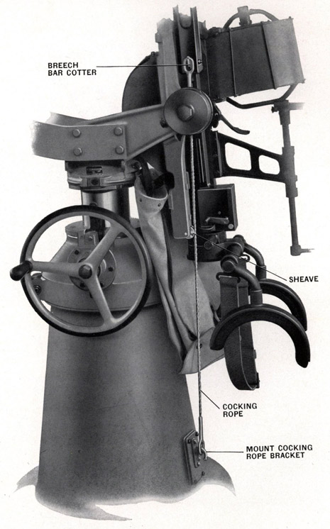
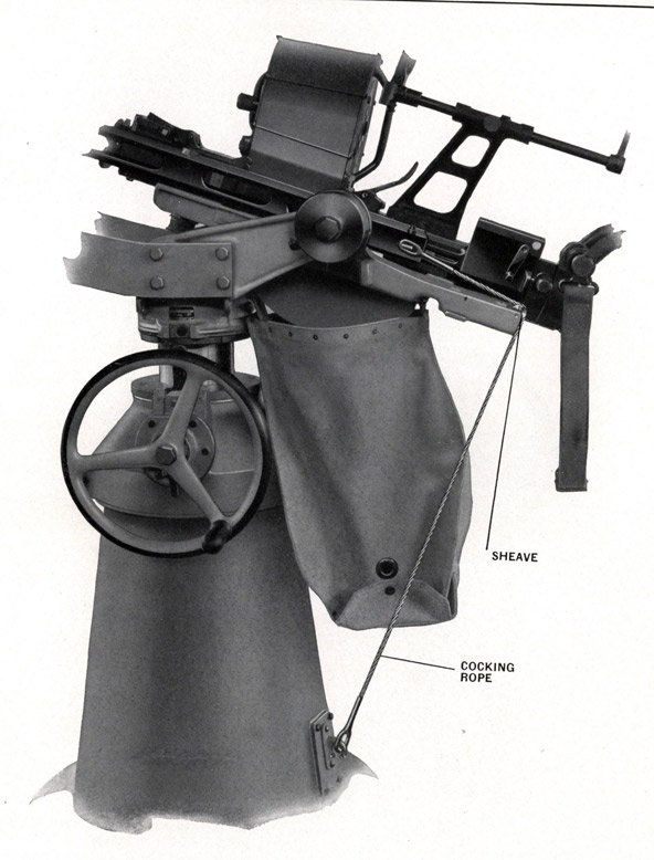
This requires the use of cocking rope (OE-2029). Lower the carriage to its lowest position. Elevate the gun to the vertical position and lock in place. Attach one end of the cocking rope to the left end of the breech block cotter (OE-1316) and train the gun so that the other end of the cocking rope is in line with the cocking rope bracket near the lower end of the mount as shown in Figure 81. Then raise the carriage slightly until the rope is taut, being sure the rope is in the groove in the sheave.
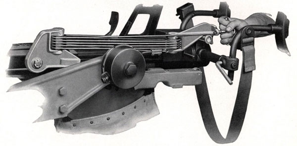
Unlock the gun cradle, grasp the hand grips or shoulder rest and depress the gun until it reaches an almost horizontal position. See Figure 82. This action will pull the breech block mass backward and the gun mechanism will be cocked when the breech block pawls can be heard to click over the parallelogram bottom levers. Then ease the recoiling mass forward slowly to the latched position by elevating the gun.
To Uncock
BE CAREFUL NEVER TO SLAM THE BREECH ON AN EMPTY GUN. Lower the carriage to the lowest position. With the gun locked in the horizontal position, hook one end of cocking rope (OE-2029) to breech block cotter (OE-1316) and the other end to the cocking rope bracket on the mount. Raise the carriage until the cocking rope is taut enough to hold the breech mass from slamming forward when released.
Remove the magazine, if in place, by pressing catch lever (OE-1043) forward while lifting the rear end of the magazine clear of its catch (OE-1046) and ejector (OE-1045). Press down with any suitable tool on the end of magazine catch (OE-1046) in order to release the interlock. See Figure 40.
Unlock the cradle lock, press trigger (OE-1220) to release the recoiling mass and elevate the gun slowly to the vertical position. As the gun is being elevated, the recoiling mass is permitted to run forward, but is held from slamming by the cocking rope. Remove the rope.
NOTE-A firm grip on the hand grips or shoulder rest should be taken at this time as the full load of the recoil springs is being released.
NOTE-In the near future the method of attaching the cocking rope to cock or uncock the gun by the cocking sheave method will be revised. This will involve the use of a shorter cocking rope (299782-2) which will be attached to a new cartridge bag anchor bolt (299804-6) instead of to the cocking rope bracket on the mount. Otherwise the procedure of operation is identical to that previously described. This latter method will permit the gun to be cocked at any angle of train and with less force applied.
123
Figure 81-Cocking rope (OE-2029) attached
preparatory to cocking gun
124
Figure 82-Cocking gun with cocking rope (OE-2029)
125
COCKING SHEAVE METHOD-FIXED HEIGHT MOUNTS
To Cock
Elevate the gun to the vertical position and lock in place. Attach one end of cocking rope (OE-2029) to the left end of breech block cotter (OE-1316) and train the gun so that the other end of the rope is in line with the cocking rope bracket near the lower end of the mount. Be sure the rope is in the groove in the sheave.
Unlock the gun cradle, grasp the hand grips or shoulder rest and depress the gun until it reaches an almost horizontal position. This action will pull the breech block mass backward and the gun mechanism will be cocked when the breech block pawls can be heard to click over the parallelogram bottom levers. Then ease the recoiling mass forward slowly to the latched position by elevating the gun.
To Uncock
BE CAREFUL NEVER TO SLAM THE BREECH ON AN EMPTY GUN. Elevate the gun and attach one end of cocking rope (OE-2029) to breech block cotter (OE-1316) and the other to the cocking rope bracket on the mount. Grasp the hand grips or shoulder rest and depress the gun until the cocking rope is taut enough to prevent the breech mass from slamming forward when released.
Remove the magazine, if in place, by pressing catch lever (OE-1043) forward while lifting the rear end of the magazine clear of its catch (OE-1046) and ejector (OE-1045). Press down with any suitable tool on the end of magazine catch (OE-1046) in order to release the interlock. See Figure 40.
Press trigger (OE-1220) to release the recoiling mass and elevate the gun slowly to the vertical position. As the gun is being elevated, the recoiling mass is permitted to run forward, but is held from slamming by the cocking rope. Remove the rope.
NOTE-A firm grip on the hand grips or shoulder rest should be taken at this time as the full load of the recoil springs is being released.
COCKING ROPE METHOD (WITHOUT COCKING SHEAVE)
ADJUSTABLE HEIGHT TRUNNION MOUNTS-CRADLES WITHOUT COCKING SHEAVE
It is necessary to raise the carriage to cock the gun mechanism and to lower the carriage to uncock it. The procedure is as follows:
To Cock
Lower the carriage to its lowest position. Elevate and lock the gun in the vertical position. Attach cocking rope (OE-2029) to the end of breech block cotter (OE-1316) and cocking rope bracket on the mount as shown in Figure 81.
Raise the column with the handwheel or pump pedals (depending on the type of mount, Mark 4 or Mark 6) until the breech pawls are heard to click over the parallelogram bottom levers as the breech block is pulled rearward. Then ease the recoiling mass slowly forward to the latched position by lowering the column and remove the cocking rope.
To Uncock
Lower the carriage to its lowest position. Elevate and lock the gun in the vertical position. Attach one end of cocking rope (OE-2029) to breech block cotter (OE-1316) and the other end to the cocking rope bracket on the mount.
126
Raise the column with the handwheel or pump pedals (depending on the type of mount, Mark 4 or Mark 6) until the rope is taut enough to keep the breech mass from slamming forward. If in place, remove the magazine by pressing catch lever (OE-1043) forward while lifting the rear end of the magazine clear of its catch (OE-1046) and ejector (OE-1045). Press down with any suitable tool on the end of magazine catch (OE-1046) in order to release the interlock. See Figure 40.
Press trigger (OE-1220) to release the recoiling mass and at the same time slowly lower the column to permit the breech mass to be eased forward. Remove the cocking rope when the gun is uncocked.
COCKING LANYARD (299905) MARK 3
This type gun cocking device has a stirrup which slips over the end of the gun barrel and a lanyard attached to each side. The lanyards are knotted to provide hand holds. See sketch on page 209.
To cock the gun the stirrup is placed over the end of the barrel and one or two men pull on each lanyard until the breech mass is pulled back into position.
HOOK AND ROPE COCKING TOOL (OE-3530) MARK 4
The single lanyard type has a hook attached to one end. There are also several knots in the lanyard to provide hand holds. The hook is attached to the left end of breech block cotter (OE-1316) and the gun is cocked by two or three men pulling on the lanyard. See sketch of lanyard on page 208.
BLOCK AND TACKLE (OE-3542) MARK 2
Another type of gun mechanism cocking device is the block and tackle type. This was designed particularly to clear severe jams and can be used by one or more men.
It is attached to the left side of the gun mechanism by engaging the head of shoulder pin (OE-3556) in the rear slot in the left breech bar and attaching the hook on the rear sheave carrier over the shoulder rest piece frame tube on Mark 2 and Mark 4 shoulder rest. On Mark 5 and Mark 5 Mod. 1 shoulder rests the hook is engaged over the sliding anchor pin (OE-1729).
Figure 83-Cocking gun with block and tackle (OE-3542)
127
To Cock
Remove the magazine. Lock the gun mechanism in the horizontal position. Attach the tool as instructed above. Then grasp the handle and pull backward, as shown in Figure 83 until the breech pawls are heard to click over the parallelogram bottom levers. After the click is heard, check by easing up on the handle.
In cases of severe jams or when the effort of more than one man is required, the hook on Mark 4 gun cocking tool can be engaged in the hole in the handle to pull back the breech mass.
To Uncock
With the cocking tool attached as described above, pull the handle back as far as possible to pull the cable taut enough to prevent the breech mass from running forward when released. Remove the magazine, if in place, by pressing catch lever (OE-1043) forward while lifting the rear end of the magazine clear of its catch (OE-1046) and ejector (OE-1045). Press down with any suitable tool on the end of magazine catch (OE-1046) in order to release the interlock. See Figure 40.
Press trigger (OE-1220) to release the recoiling mass and at the same time slowly ease up on the handle of the cocking tool to allow the breech mass to run forward.
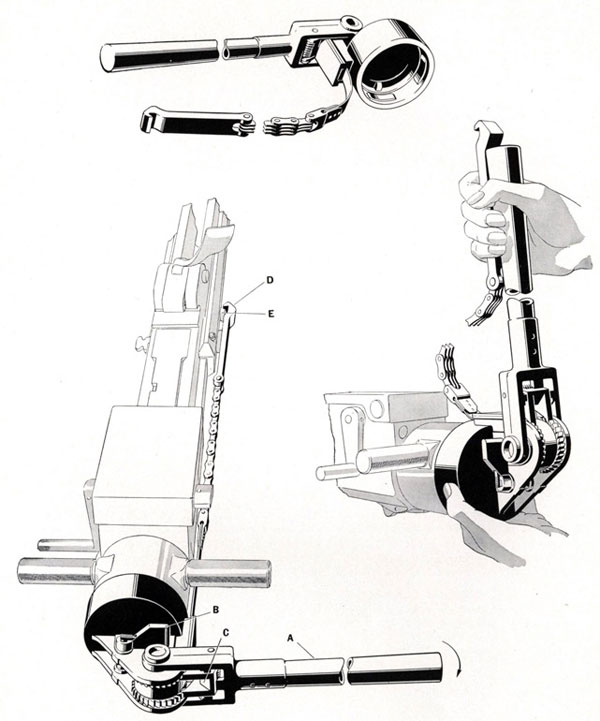
RATCHET TYPE COCKING TOOL MARK 1
Still another cocking device, which is in limited service, is the ratchet type cocking tool. See Figure 84. This can be used only on gun mechanisms which are fitted with the hand cocking catch plate (OE-1044) on the rear end of the right breech bar, and the separate hand grips (OE-1036). The tool is attached to the rear end of the gun after removing the shoulder rest from the hand grips.
To Cock
After attaching the device to the hand grips, attach the hook (E), Figure 84, on the end of the chain to catch plate (OE-1044) (D) on the right breech block. Move the ratchet handle (A) back and forth until the breech pawls can be heard to click over the parallelogram bottom levers when the breech block has been pulled far enough to the rear. Then ease off on the handle until the sear (OE-1317) engages trigger hook (OE-1216).
To Uncock
After attaching the device to the hand grips as instructed under "To Cock," move the ratchet handle (A) until the chain is taut enough to hold the breech mass from moving forward. If in place, remove the magazine by pressing the catch lever (OE-1043) forward while lifting the rear end of the magazine clear of its catch (OE-1046) and ejector (OE-1045). Press down with any suitable tool on the end of magazine catch (OE-1046) in order to release the interlock. Press trigger (OE-1220).
Pull on the handle and then release the holding pawl by pressing forward on the pawl lever (B). Hold this lever down and at same time allow handle to rotate slowly forward. Apply finger pressure to the handle pawl (C) and return the handle to the starting position. Repeat above operation until the breech mass has been moved forward.