There are five types of sights in use: 20 mm. Sights Mark 2, Mark 4, Mark 4 Mod. 1, and Mark 5 and Gun Sight Mark 14 Mod. 2.
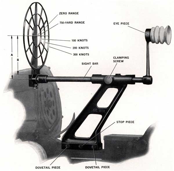
Figure 68-Sight Arrangement-Mark 4
Mark 4 and Mark 4 Mod. 1 sights can be easily distinguished by their name plates. Mark 4 sight is illustrated in Figure 68. The bracket on Mark 4 Mod. 1 is one inch lower than the one on Mark 4, and has less backward slope. This brings the line of sight one inch closer to the gun. Changes in the sight bar maintain
the eye piece in the same fore and aft location.
83
The Mark 2 sight is identical in appearance to Mark 4, except that it has an adjustable back sight.
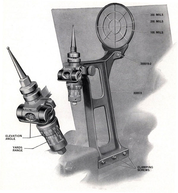
Mark 5 sight, illustrated in Figure 69, uses a single adjustment which compensates for both range and elevation and has a simple elevation indicator.
Operating instructions and boresighting information for Gun Sight Mark 14 Mod. 2 are covered in Ordnance Data 4429 which is issued with the gun sight.
USE OF SIGHTS MARK 2, MARK 4, AND MARK 4 MOD. 1
The Mark 2 sight has an adjustable backsight having two positions: One for 750 yards range (marked "Normal"), and one for parallel bore sighting (marked "Zero Line Up").
Mark 4 and Mark 4 Mod. 1 sights are calculated for a horizontal range of 750 yards. The backsights are fixed. The foresight horizontal bar is used for 750 yards range and there is a white mark on the vertical center bar-to indicate parallelism.
The line of sight from the backsight (set to Normal in case of Mark 2) to the center of the foresight is 24.5 minutes below a line parallel to the axis of the bore of the gun. This gives 24.5 minutes elevation of the bore above the line of sight, which corresponds to the elevation required for a horizontal range of 750 yards.
The 100, 200, and 300-knot rings indicate the approximate amounts of lead required, at average ranges, against targets whose speed components across the sight are 100, 200, and 300 knots, respectively.
SHIPPING AND UNSHIPPING THE SIGHT-MARK 4 AND MARK 4 MOD. 1
To ship the sight assembly on the gun, see that the three clamping screws (OE-1192) on the right hand side, see Figure 69, are loosened and that the two dovetail pieces (OE-1190), see Figure 68, and stop piece (OE-1191) are backed out of the sight bracket far enough to permit the sight to be set down over the vee ways on the breech casing. Set the sight bracket down over the ways on the breech casing. This can be done only when the rear of the bracket is back close to the trigger housing. Slide the sight forward until the rear edge of the sight bracket is flush with the back edge of the sight mounting ways on the breech casing. Turn the center clamping screw until the stop piece engages in the notch in the mounting ways. When this is engaged the sight bracket cannot be moved longitudinally. Do not tighten fully. Next tighten the front and rear clamping screws with spanner (OE-1189) and then tighten the center clamping screw firmly.
To unship the sight assembly, loosen the three clamping screws (OE-1192), see Figure 69, using spanner (OE-1189). The center screw must be backed out five or six turns and then pushed toward the left side until the stop piece, see Figure 68, is disengaged from the notch in the breech casing. Then slide the sight assembly back toward the trigger cover and lift it off the gun.
PREPARING SIGHT FOR STOWING-MARK 4 AND MARK 4 MOD. 1
When stowed in the sight box, the foresight is rotated 150 degrees to the left from the vertical, or firing position. This can only be done after unshipping the sight from the gun.
On Mark 2 and Mark 4, loosen the sight bar clamping screw, Figure 68, and back it out until the sight bar can be moved forward. Slide the sight bar forward through the bracket as far as it will go. Then rotate the foresight 150 degrees to the left. In this position the sight bar clamping screw will engage another hole in the sight bar. The clamping screw should be tightened securely.
On the Mark 4 Mod. 1 sight, loosen and back out the sight bar clamping screw, Figure 68. The foresight can then be rotated 150 degrees to the left and the sight bar clamping screw tightened into a hole in the sight bar to secure the assembly in this position.
84
Figure 69-Sight Arrangement-Mark 5
85
CAUTION-When installing a sight on the gun, care should be taken that the sight bar clamping screw is properly engaged and tightened in the aligning hole in the sight bar. This is necessary to properly align the sight.
REPLACEMENT OF FORESIGHT ASSEMBLY-MARK 2, MARK 4, AND MARK 4 MOD. 1 SIGHTS
Should it be necessary to replace a foresight assembly, the gun must be boresighted and the foresight adjusted to the proper position as described on page 88.
MARK 5 SIGHT-DESCRIPTION
Sight bracket assembly (300019), Figure 69, is designed to permit the installation of this sight on both Mark 2 and Mark 4 guns.
Foresight assembly (300019-1) is attached to the front of the bracket with two tapered shank screws (300019-2). The foresight rings set at distances from the center of the foresight equal to 100 and 200 mils (U. S. N.). The inside of the supporting ring is 300 mils (U. S. N.) from the center of the sight.
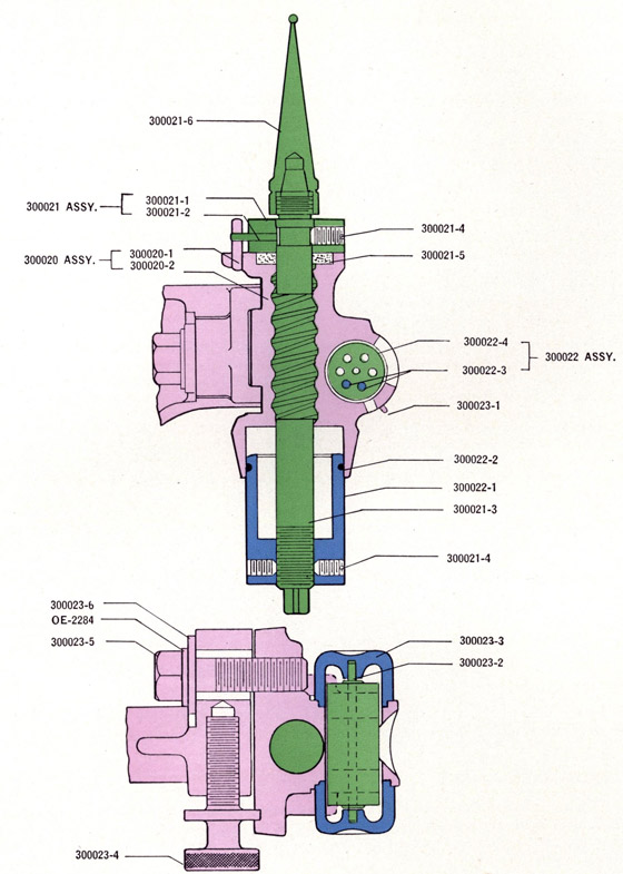
Rear sight support assembly (300020), Figure 70, is accurately positioned by its spline in a mating recess in the sight bracket. It is adjustable horizontally by means of adjusting screw (300023-4) and is locked in position by screw (300023-5). The lower extremity of the rear sight support (300020), Figure 70, carries an elevation scale graduated in degrees.
Elevation indicator is mounted on rear sight support assembly (300020). This is read directly through a small opening located conveniently for the gunner when in firing position. The elevation readings are taken from drum assembly (300022) which contains two small weights (300022-3) and rotates freely on drum shaft (300023-2). The ends of the shaft operate in two bearing caps (300023-3) which are held in place by retainer (300023-1).
Rear sight collar assembly (300021), Figure 70, is used only for setting the sight at original assembly. Its adjustment should never be disturbed except when rear sight pin (300021-3) is removed for some reason or to allow for adjustments when bore sighting when the guns are in service. When replacing the pin the procedure under "Servicing", page 87, should be carefully followed. Also see "Bore Sighting" on page 88.
The rear sight pin assembly consists of pin (300021-3), range adjustment cylinder (300022-1), and set screw (300021-4). The cylinder, graduated in yards range, is firmly fixed to the pin by the set screw when the sight is originally adjusted and this relative positioning should not be disturbed.
Rear sight pin tip (300021-6) screws onto the end of sight pin (300021-3). A taper on the end of the sight pin fits in a corresponding seat at the lower end of the pin tip.
Friction spring (300022-2), Figure 70, is placed outside of range adjusting cylinder (300022-1) for the purpose of maintaining the setting of the cylinder.
OPERATION-MARK 5 SIGHT
It is only necessary for the gunner to choose his elevation and range and set the range adjusting cylinder. Elevate the gun to the angle at which firing is expected to occur. Observe elevation indicator reading. Estimate range and turn the range adjusting cylinder until the estimated range figure appears opposite the observed elevation figure.
The insert in Figure 69 shows the proper adjustment for 1100 yards range and 30° elevation.
86
Figure 70-Mark 5 sight sectional view
87
SERVICING-MARK 5 SIGHT
Included with each sight in the sight box is one spare foresight assembly, three spare rear sight pin tips, and a 1/4" square socket with hinge handle.
Foresight-To change remove the two cap screws (300019-2), Figure 69, and take off the foresight. Place new foresight in position with large end of tapered holes and rivet head facing forward and reassemble the two screws. The taper on the screws matches with the tapered recesses in the foresight and, therefore, the error introduced by changeover is negligible.
Rear Sight Pin Tip-Rotate range adjustment cylinder (300022-1), Figure 70, until pin (300021-2) in initial adjustment collar (300021) is about one half turn away from the stationary vertical stop pin (300020-1) in the top of the rear sight support assembly (300020) (this procedure will prevent possible damage to stop pin by wrench slipping, etc.). Hold head on lower end of sight pin (300021-3) stationary with the 1/2" socket and hinge handle provided, and unscrew the tip (300021-6) from the pin, using an adjustable or 1/2" end wrench.
Install the new tip by reversing the foregoing operations, taking every precaution that the new pin tip is pulled down tight against the tapered seat. Setting of the rear sight collar assembly (300021) should not be disturbed during this operation.
Rear Sight Pin and Range Adjusting Cylinder Assembly-If for some reason it should become necessary to remove this, proceed as follows: Remove rear sight pin tip from sight pin according to foregoing instructions. Strip rear sight pin initial adjustment collar assembly (300021) by loosening set screw (300021-4). Remove sight pin (300021-3) and range adjustment cylinder (300022-1) as an assembly by screwing the pin downward. Neither loosen nor remove the range adjustment cylinder from the pin.
To reinstall these parts thread the rear sight pin assembly upward into its recess until the upper end of sight pin (300021-3) starts to project through sight support (300020-2). Reinstall felt seal (300021-5) in recess. Place rear sight collar assembly (300021) over upper end of sight pin and screw pin assembly upward until shoulder on sight pin (300021-3) is flush with top of collar assembly (300021). It will now be found that the 600 yard mark on range adjusting cylinder (300022-1) will register close to the 75 degree mark on the elevation scale. Set the 600 yard range mark exactly on the 75 degree elevation mark and hold in this location until rear sight collar assembly (300021) is turned clockwise (as viewed from above) against stop pin (300020-1). Then lock the collar to the sight pin with set screw (300021-4).
ALTERNATE REAR SIGHT PIN TIPS-MARK 5 SIGHT
As rounds fired on a barrel increase, bore and chamber wear occur to a degree definitely lowering the muzzle velocity of the projectile. Muzzle velocity and range of projectile decrease in like proportion, and therefore, some means of compensation for decrease in range with barrel wear must be provided to maintain sight accuracy with lowered projectile flight. To provide this type of compensation for the Mark 5 Sight, pin tips of different heights are furnished for first third, second third, and last third of normal barrel life. These pins are identified by grooves on hexagonal section as follows: First third has one groove (300021-6), second third has two grooves (300021-7), and last third has three grooves (300021-8). At the interval of barrel life corresponding to the noted classifications, pin tips should be changed accordingly to maintain sight accuracy with a changed trajectory of projectile. See "Life of the Gun Barrel," Page 111.
88
BORE SIGHTING INSTRUCTIONS
GENERAL
1. The bore sight is used to establish a line of sight coincident with the axis of the bore of 20 mm. A.A. guns. The line of sight, thus established, is used to check the line of sight of a front area type of open sight or of the Gun Sight Mark 14 Mod. 2, whichever is used. A bore clear mirror, an empty 20 mm. cartridge case modified as described hereinafter, and a set of crosslines at the muzzle comprise the bore sight.
2. Modification of cartridge case-A 3/32-inch diameter hole, centered with respect to the case
periphery, is drilled through the primer end of an empty 20 mm. cartridge case. A suitable means may be provided for removing the cartridge case from the bore. The case, thus modified, is used to position the observer's eye relative to the axis of the barrel, thus reducing parallax and establishing a line of sight more nearly coincident with the axis of the gun barrel.
3. Crosslines at muzzle-In addition to the mirror and modified cartridge case, it may be found convenient to improvise a set of crosslines attached at the muzzle to assist in lining up the line of sight on the target. These may be made by lashing two wires to the muzzle bell. The wires should be perpendicular to each other and have their intersection on the axis of the gun bore. A second method is to solder the two wires to a cylindrical shell of the proper size to fit over the muzzle bell. Here again the wires should be perpendicular to each other and have their intersection at the center of the bore.
NOTE-Since an error of 1/16-inch in positioning the intersection of the crosslines on the axis of the bore will produce only about one mil error in the line of sight, the positioning may be done by eye.
PROCEDURE
4. The procedure used in bore sighting a 20 mm. gun equipped with an open ring sight is as follows:
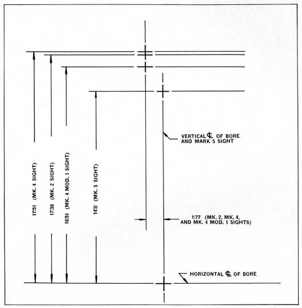
(a) Prepare a target or batten by ruling vertical and horizontal lines whose intersections represent the position of the line of sight with respect to the axis of the gun barrel. See Figure 71. As a starting point for the layout, the point where the axis of the bore intersects the target should be chosen. The other lines may then be laid out from this point.
NOTE-The lines should be laid out as accurately as possible since the bore sighting distances involved will be short, and mistakes in the layout will cause appreciable errors in the bore sighting results.
(b) Secure the gun at 5 degrees elevation by means of the cradle locking bolt. Place the target in position in front of the gun and as far distant as the ship's structure will permit, but near enough to make the target lines clearly visible. The target should be perpendicular to the gun axis with the gun at 5 degrees elevation.
(c) Seat the modified cartridge case firmly in the gun barrel, mount the bore clear mirror in position on the breech casing, and secure the cross wires at the muzzle. The line of sight is now coincident with the axis of the gun barrel.
(d) Adjust this line of sight by shifting the batten, so that the muzzle cross wires center on their corresponding horizontal and vertical lines on the target. Check the batten after this adjustment to see that it still is perpendicular to the gun axis.
(e) Now check the line of sight through the rear sight and foresight to see that it lines up on the intersection of the vertical and horizontal lines which represent the position of this line of sight with respect to the bore.
89
Figure 71-Bore Sight Target
90
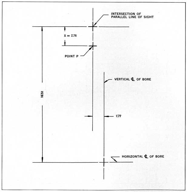
Figure 72-Bore Sight Target for 20 mm. Sight Mark 4 Mod. 1
Locating point "P" for adjusting line of sight to intersect trajectory of projectile at 1000 yds. range and 45° elevation (See example on Page 91.)
91
NOTE-To do this accurately, it will be necessary to position the eye about 24 inches back of the rear sight. Further, be sure to use the parallel bore sighting mark (small notch above the horizontal bar) on the foresight of 20 mm. Sights Marks 4, and 4 Mod. 1, and to have the rear sight of 20 mm. Sight Mark 2 in the "zero line up" position. For Sights Mark 5, see paragraph (6).
(f) If errors in either elevation or deflection are found by the above procedure, adjustments made as described hereinafter will be necessary.
5. The following methods of adjustment for the errors found by bore sighting are applicable to the foresight of 20 mm. Sights Mark 2, Mark 4, and Mark 4 Mod. 1.
(a) If the line of sight does not intersect its vertical line on the target, a deflection error is apparent. It is corrected by loosening the two clamping bolts near the bottom of the ring foresight and moving the sight horizontally until the line of sight intersects the vertical line.
(b) If the line of sight is in error in a vertical direction, an elevation adjustment is made by loosening the same two clamping bolts as in (a) above, and then moving the foresight up or down by means of the adjusting collar at the bottom of the clamp. (On the Mark 2 Sight there are two collars to be adjusted).
The procedure outlined above will adjust the line of sight through the center of the rear sight and the center of the foresight to intersect the trajectory of the projectile at a horizontal range of approximately 750 yards. (This is true in the case of Sight Mark 2 when the adjustable rear sight is set to the "Normal" position). To set the line of sight so that it intersects the trajectory of the projectile at any desired range and elevation, the following formula can be used for locating a corresponding point, (P), Figure 72, on the bore sight target where the line of sight must intersect.
X = D [(.00349) A + 5.6671/R]
where D = distance, in feet, from rear sight to batten.
R = range, in yards.
A = super-elevation of sight, in minutes, (from 20 mm. A.A. Range Tables).
X = vertical distance, in inches, on the batten from intersection of parallel line of sight to point (P).
When the distance (X) has been determined from the above formula, mark point (P) on the batten as shown in Figure 72 (for the case of a Mark 4 Mod. 1 Sight). With the target set up and adjusted as outlined in paragraphs (4b), (4c), and (4d), loosen the clamping bolts, move the foresight up or down until the line of sight through the center of the rear sight and the center of the foresight intersects the mark point (P) on the batten and then tighten the clamping bolts. Note that in this case the center of the foresight is used and not the parallel bore sighting notch above the horizontal bar on the foresight of 20 mm. Sights Marks 4 and 4 Mod. 1. On the 20 mm. Sight Mark 2, the rear sight must be in the "Normal" position. The following example will serve to illustrate the method of setting the line of sight to intersect the trajectory of the projectile at any desired range and elevation.
Example:-It is desired to adjust the line of sight on a 20 mm. A.A. Gun equipped with a Mark 4 Mod. 1 Sight so that the line of sight will intersect the trajectory of the projectile at a range of 1000 yards and an elevation of 45 degrees. The gun mount installation permits the location of the batten at a distance of 25 feet forward of the rear sight.
92
(a) In the formula
X = D [ (.00349) + 5.667/R]
D = 25 feet
R = 1000 yards
A = 30 minutes (from 20 mm. A.A. Range Tables).
Substituting these values in the formula,
X = (25) [(.00349) (30) + 5.667/1000]
X = 2".76
(b) Lay off on the batten the distance X = 2".76 vertically downward from the mark indicating the point where the parallel line of sight intersects the batten. Mark the point (P) as indicated in Figure 72.
(c) Set up the batten at a distance of 25 feet forward of the rear sight and adjust as outlined in paragraphs (4b), (4c) and (4d). Loosen the clamping bolts on the foresight and move the foresight vertically until the line of sight through the center of the rear sight and the center of the foresight intersects the batten at point (P). Tighten the clamping bolts. The line of sight is now adjusted to intersect the trajectory of the projectile at 1000 yards range and 45 degrees elevation.
6. On 20 mm. Sights Mark 5, if the line of sight does not intersect its vertical line on the batten, it may be corrected by loosening the rear sight support locking screw (300023-5) and moving the rear sight pin horizontally by means of the adjusting screw (300023-4) until the line of sight intersects the vertical line. To check the line of sight in the vertical direction, set the 1000 yard range mark on the range adjustment cylinder to line up the 75 degree mark on the elevation scale. If the line of sight through the center of the ball on the rear sight pin tip and the center of the foresight does not line up with the horizontal line on the batten, the following adjustments should be made:
(a) Loosen the initial adjustment collar (300021-1) by means of the set screw (300021-4). Loosen the range adjustment cylinder (300022-1) from the rear sight pin by means of the set screws (300021-4).
(b) Turn the square head on the rear sight pin until the line of sight intersects the horizontal line on the batten.
(c) Hold the rear sight pin stationary in the above adjusted position and rotate the range adjustment cylinder until the 1000 yard mark is exactly in line with the 75 degree mark on the elevation scale.
(d) Tighten the range adjustment cylinder to the rear sight pin by means of the set screws.
(e) Align the 600 yard mark on the range adjustment cylinder with the 60 degree mark on the elevation scale and rotate the initial adjustment collar clockwise (as viewed from above) to the stop pin (300020-1). Lock the collar in this position by means of the set screw (300021-4) with the base of the collar in contact with the sight support.
It should be noted that the foregoing adjustment does not provide an exact super-elevation setting for 1000 yards range and 75° elevation. In order to simplify the sight, certain approximations have been necessary and when the bore sighting adjustments are made as outlined above, the error throughout the range and elevation scales is reduced to a minimum.
The single groove rear sight pin tip (300021-6) should always be used when bore sighting. The pin tips bearing two grooves (300021-7) and three grooves (300021-8) are provided to compensate for bore erosion during the life of the gun, but should never be used for bore sighting purposes.
93
94
95
96
SHOULDER REST
Chapter 8
MARK 2 AND MARK 4 SHOULDER REST ASSEMBLY (OE-1500)
On this type assembly the shoulder rest is separate from the hand grips. The shoulder rest, however, is turned onto the rear face of the hand grips and locked in place by a catch attached to the bottom of the shoulder piece frame.
The shoulder rest pads, which are of rubber with a steel reinforcement band, are rotatable to conform to the gunner's shoulders.
A telescoping type shoulder frame holder, adjusted by a knurled knob on the right end of the threaded spindle permits lateral adjustment of the shoulder rest pads to meet the gunner's shoulder width.
The shoulder rest strap is fitted with a buckle at the center to permit it to be adjusted to the gunner's requirements.
SHOULDER REST ASSEMBLIES MARK 5 AND MARK 5 MOD. 1
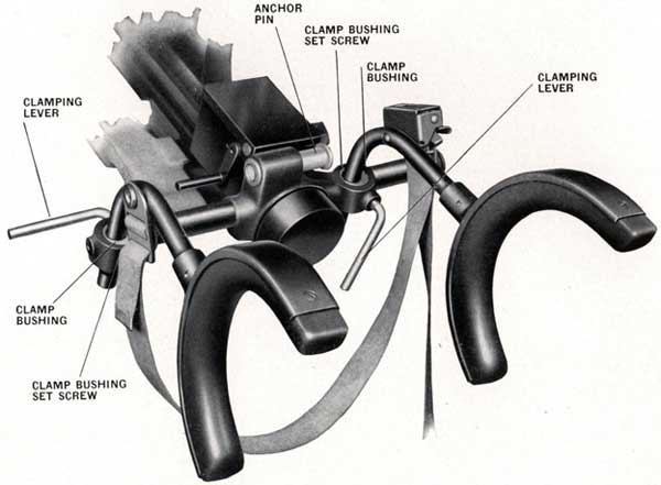
Two types of shoulder rests with integral hand grips are used. Mark 5 shoulder rest has rubber shoulder pads as shown in Figure 73. Mark 5 Mod. 1 shoulder rest is identical to Mark 5, except that it has fabric straps instead of rubber pads. This latter type is being discontinued in production.
Figure 73-Mark 5 shoulder rest
97
The integral hand grips and shoulder rest design provides right and left rest pads and support assemblies which have several adjustments to permit the gunner to fit himself into the most advantageous position for his particular physical proportions. The adjustments are quickly and easily made as noted below.
NOTE-Due to interference when Mark 14 Mod. 2 gun sight is installed, revisions are being made in the Mark 5 shoulder rest whereby the strap anchor plate (OE-1719) is being assembled on the right shoulder piece support instead of on the left support. The position of the strap is then reversed so that the buckle is attached to the rivet head on the left side to provide the clearance desired for the gun sight support. Where desired, this revision can be made on board ship by removing rivets (OE-1288) and reassembling the anchor plate on the right support.
Due to cancellation of the Mark 4 block and tackle type cocking tool, further changes are being effected in the Mark 5 shoulder rest which omit anchor pin (OE-1729), Figure 73, used for attaching the rear sheave carrier. The lug for the pin will also be omitted from the frame rest casting as soon as pattern changes can be effected.
1. Vertical Adjustment-
Each shoulder rest support may be adjusted up or down after loosening the clamping levers (OE-1714), see Figure 73, at the hand grip. The adjustment permits the gunner to raise or lower his shoulders in relation to the gun sight.
2. Lateral Adjustments-
Each shoulder rest support may be rotated laterally with respect to the hand grip in either direction after loosening the clamping levers in the same manner as for vertical adjustment. These adjustments have two functions: They permit the gunner to shift his body sidewise for proper alignment with the gun sight and also permit swinging the arm rests in or out to obtain the proper span to fit the gunner's shoulders.
3. Shoulder Pad Angular Adjustment-
Each shoulder pad is free to rotate about the end of the shoulder piece support over a range of about 30 degrees on each side of the true vertical position. This adjustment permits the shoulder rest pads to assume a natural position against the gunner's shoulders and it will be found in most cases that both pads tend to tilt in at the top.
A movable cocking tackle anchor pin (OE-1729), Figure 73, is provided at the center of the hand grip frame to serve as an anchor for the rear sheave carrier when cocking the gun with (OE-3542) cocking tackle assembly. When using this pin it must be pushed to the extreme left side. At all other times it should be kept in the extreme right position for clearance purposes.
INSTRUCTIONS FOR USE-
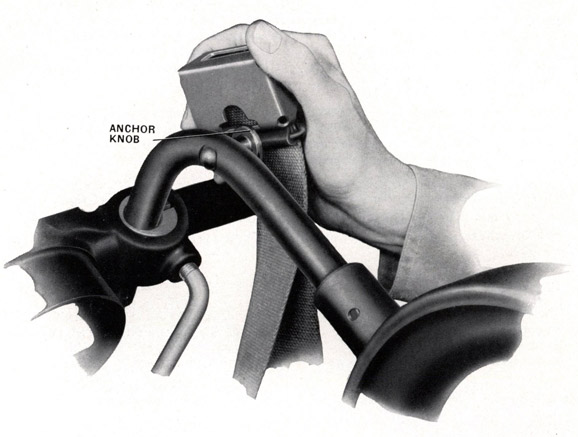
1. With gunner in approximate position, pass shoulder strap around gunner's back and hook buckle over anchor knob on right side of shoulder piece support, see Figure 74.
98
Figure 74-Hook buckle over knob
99
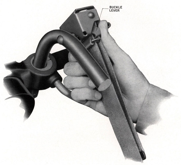
2. Release buckle by pressing lever inward as shown in Figure 75.
Figure 75-Press lever inward to release
100
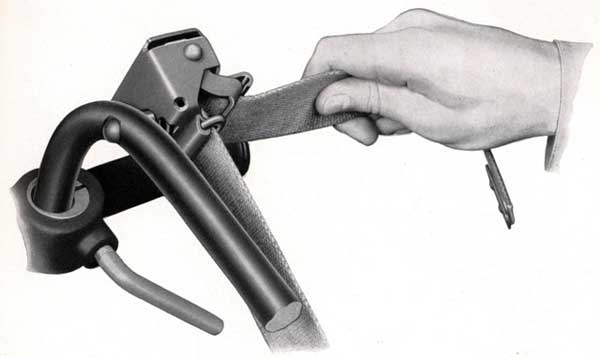
3. Pull end of strap and tighten to desired position, see Figure 76.
Figure 76-Pull strap downward to adjust
101
4. Lock strap by outward pull on free end and release, see Figure 77.
Figure 77-Pull strap outward to lock
ADJUSTMENT OF CLAMPING LEVERS
The clamping bushings (OE-1711 or OE-1712) which provide means for clamping the shoulder rest supports, are retained in the frame by stop screws (OE-1713).
Adjustment of clamping levers (OE-1714) to desired angle (and also to take up wear) can be made with clamping levers in released position by rotation of bushing stop screws in the proper direction. Stop screws should not protrude more than 14 inch from the bosses on the hand grip frame.
102
103
104
AMMUNITION
Chapter 9
AMMUNITION FOR 20 mm. A.A. GUNS MARKS 2 AND 4
There are SIX types of ammunition as follows:
(A) High Explosive, with Tracer, projectile type "HL" loaded with Pentolite, an explosive formed by combining equal parts of TNT and PETN. Color of projectile-Blue.
(B) Same as (A) except projectile is loaded with Tetryl. Color of projectile-Light Grey.
(C) High Explosive, without Tracer, projectile type "HB" loaded with Pentolite. Color of projectile- Yellow.
(D) Same as (C) except projectile loaded with Tetryl. Color of projectile-White.
(E) Blind loaded with Tracer. Color of projectile-Dark Green Grey with 1/8" wide Yellow Band.
(F) Blind loaded and plugged. Color of projectile-Dark Green Grey.
NOTE-The above colorings apply to 20 mm. A.A. Ammunition only for Mark 4 and Mark 2. Do not confuse with colors used in other ammunition.
LOADED AND FUZED PROJECTILE WITH TRACER
This projectile has about one-half of the cavity loaded with pyrotechnic tracer mixture designed to burn about 3 3/4 seconds. The forward part of the projectile cavity space is loaded with pressed Tetryl or Pentolite. These explosives are approximately equivalent in destructive value. The fuze used is a simple air-column type with no moving parts. Its action is initiated by impact, either head-on or glancing. The closing disc being displaced into the fuze body by impact, an air-column is instantaneously compressed and wiredrawn through an inner disc. The rate of temperature-pressure rise is sufficient to ignite lead azide, which in turn ignites pressed Tetryl in the detonator, and ignition of the burster charge is effected. The fuze is designed definitely not to function on the equivalent of 0.012 inch dulalumin plate (or lighter), but definitely to function on the equivalent of one-eighth inch mild steel plate or heavier. The fuze is not equipped with any bore-safe feature, and will act whenever the closing disc is displaced into the fuze with sufficient force. This projectile is not equipped with a self-destruction feature.
LOADED AND FUZED PROJECTILE WITHOUT TRACER
This projectile is similar to the "Loaded and Fuzed Projectile with Tracer" described above, but has a burster charge that is approximately twice as great.
BLIND LOADED AND TRACER TYPE OF PROJECTILE
This projectile has the burster charge cavity inert-loaded to weight, except for the tracer, and is plugged at the nose with a fuze body, assembled with no detonator.
BLIND LOADED AND PLUGGED PROJECTILE
This projectile has the burster charge cavity inert-loaded to weight, and is plugged at the nose with a fuze body assembled with no detonator.
PROPELLANT
The powder is an FNH type of nitro cellulose powder. It is a single-perforated grain with weight of charge to give 2725 foot-seconds at 90 degrees F. with standard projectiles. Surveillance and breakdown of
105
AMMUNITION MAINTENANCE
20 mm. antiaircraft cartridges are covered in separate correspondence. Instructions regarding this ammunition are similar to those currently effective regarding 1.10 inch 75 caliber ammunition.
AMMUNITION CONSTRUCTION
The cartridge case is of the usual type with a conventional percussion cap.
HIGH EXPLOSIVE SHELL
An H. E. shell must never be fired through a muzzle cover. To prevent such an occurrence the last two rounds loaded in each magazine should have blind loaded projectiles.
AMMUNITION PACKING
The first shipments of ammunition were made in wooden boxes. Later shipments are in metal boxes containing 150 rounds in each box. The completely filled metal box weighs 115 pounds. Rounds are packed in separate cardboard tubes and each tube is lined with greaseproof paper so that the grease on the cartridges will not be absorbed. The cardboard tube is open at both ends but is fitted with an inner ferrule to prevent the cartridges from clearing the tube fuze first. The cartridge is a light friction fit in the tube.
UNPACKING CARTRIDGES
Use care in withdrawing greased cartridges from their packing tubes. The most efficient way of getting them free of the tube, is to push on the nose of the fuze with a finger while firmly holding the packing tube. As previously stated, there is an inner ferrule in the tube to prevent the cartridge from clearing the tube fuze first. Pushing on the nose of the fuze starts the cartridge out of the tube, when it immediately becomes a loose fit and care must be taken not to permit the greased cartridge to come adrift and fall.
INSPECTION OF CARTRIDGES
Stoppages of the gun have occurred which appeared to have been caused by the presence of hair from ammunition packing material getting into the mechanism. Steps have been taken to eliminate this type of packing, but a large amount of ammunition has already been issued. At the first opportunity, and in any event before loading it into the magazine drums, ammunition should be examined to see that it is free of hair; and if hair or dirt is found it should be removed. If grease is removed in this process, it must be replaced.
NOTE-Pay attention to the need of a complete covering of mineral grease on all cartridge cases.
GREASING AMMUNITION
All 20 mm. A.A. Mark 2 and Mark 4 ammunition MUST BE COMPLETELY COVERED WITH A LIGHT COAT OF MINERAL GREASE BEFORE BEING LOADED INTO THE MAGAZINE.
The ammunition is usually packed greased. However, this grease tends to dry off. Whether cartridges are packed greased or not, they should be regreased before loading the magazine.
NOTE-A small amount of mineral grease, applied shortly before firing, to the cartridge case that is visible in the magazine mouthpiece, will assist in preventing a jam in the gun barrel.
Dry ammunition or ammunition with insufficient grease will jam in the gun chamber when fired and extraction will be very difficult, if not impossible. See Page 110 for use of torn cartridge extractor.
106
NOTE-Oil must not be used as a substitute for mineral grease.
Sufficient grease should be present on all cartridge cases to be easily felt by the fingers. An excess should be avoided.
CAUTION-Do not grease the rear end of the cartridge cases as the grease has a tendency to percolate inward past the percussion cap. NEVER USE OIL.
DROPPING CARTRIDGES
Care must be used in handling the greased cartridges. They must not be dropped or struck a heavy blow on either the nose or the cartridge base. Any cartridge that has been dropped over five feet is to be set aside and turned in to any Naval Ammunition Depot at the first opportunity.
NOTE-Rounds that have been possibly damaged as described above are not to be considered unsafe, except for firing. If used for firing, they might result in dud action and, therefore, should be refuzed before firing.
CARTRIDGE BAG
If prolonged firing is necessary, then the cartridge bag should be emptied frequently. A cartridge bag that gets too full gets in the way of the gun layer at high gun elevations.
NAVAL AMMUNITION DEPOT
Secure, and turn in to a Naval Ammunition Depot, all ammunition boxes, internal containers, fired cartridge cases, packing tubes and dropped or damaged cartridges. The tear strip of the top of the internal container may be discarded.