The tripping latch is the device which, when the
torpedo starts out of the tube, engages and trips
the starting lever (a trigger-like projection from the
torpedo) to start the torpedo's engine.
The tripping latch is a hammer-shaped lever,
about six inches long and five-eighths of an inch
thick. It is so arranged and placed that it engages
the torpedo starting lever when the torpedo has
moved forward three-fourths of an inch after the
firing charge has started it out of the tube.
When a torpedo is being loaded into the tube, the
tripping latch must be raised, or retracted, from the
barrel, so there will be no interference with the
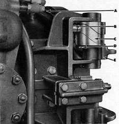
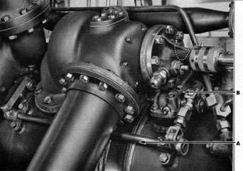
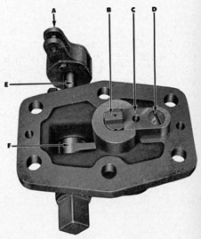
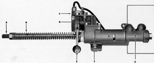
Figure 199 The breech door hinge bracket, showing
the tripping latch am. (A) Tripping latch arm, which
connects with operating shaft as shown in Figures 200
and 201; (B) Roller; (C) Tripping latch cam; (D) Key which rotates cam when engaged by (E) Free end of
upper arm of breech door.
free movement of the torpedo as it is moved forward into place in the tube.
However, the mechanism is so designed that the
tripping latch is raised out of the tube as the breech
door is being opened, and it is lowered back into
position as the breech door is being closed. This is
done by means of a cam attached to the upper hinge
pin of the breech door, a key on the cam being
engaged by the end of the upper arm of the breech
door as it is being opened, thereby rotating the cam,
as illustrated and described in Chapter 3 (see especially Figures 24 to 30, on pages 26 and 27). The
cam is also shown here in Figure 199.
Figure 200 shows the linkage between the cam
on the breech door, the operating shaft, and the
tripping latch housing, in the position when the
breech door is closed. Figure 201 shows the linkage in the position when the breech door is open.
Another view of the tripping latch housing and the
linkage with the breech door is shown in Figure
202, this illustrating the position of the tripping
latch housing with relation to the poppet valve and
other operating units.
An interior view of the tripping latch housing is
shown in Figure 203, illustrating the latch lowered into the barrel to contact and trip the torpedo
starting lever.
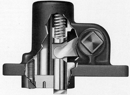
The curvature of the cam, shown in Figure 199,
is such that the tripping latch is in the extreme
down position before the breech door is entirely
closed. Hence, this position of the tripping latch can
be verified by sighting into the barrel before fully
closing the breech door. During the opening of the
breech door, the tripping latch cam remains in
neutral position for the first 45 degrees of the opening of the door, so that the latch can also be observed
by sighting down the barrel as the door is being
106
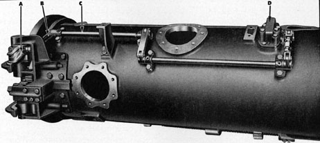
Figure 200 Linkage between cam on breech door hinge, operating shaft, and tripping latch housing, in breech door
closed position. (A) Cam and roller; (B) Latch arm; (C) Operating shaft; (D) Tripping latch housing.
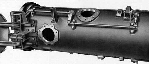
Figure 201 Tripping latch linkage in breech door open position.
107
opened. It is considered good operating policy to
observe carefully the position of the tripping latch
both on opening and on closing the breech door
when loading a torpedo.
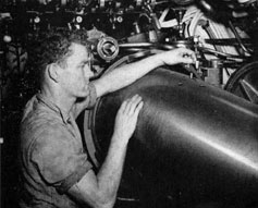
The starting lever on the torpedo, which is engaged by the tripping latch to open the torpedo
starting valve and set the operating mechanism in
the torpedo in action, is shown in Figure 204.
Here, the operator is removing a safety stick from
the starting lever preparatory to loading the torpedo
into the tube. This safety stick is inserted to protect
the starting lever, and to prevent it from being tripped unintentionally or accidentally while the torpedo is being handled up to the time of loading
into a torpedo tube.
There are certain differences between the tripping
latch as installed on some of the earlier submarines
and those on vessels of more recent construction.
This is due to the fact that the somewhat limited
movement of the tripping latch in the original design was found, after moderate wear, to be insufficient to insure proper adjustment by means of the
turnbuckle arrangement provided, so as to permit
the latch to project the required amount within the
bore when down but with all lost motion taken out
in the up direction, and, at the same time, not
project within the bore when up but with all the
lost motion taken out in the down direction.
This last condition has no effect in connection
with torpedoes, as the slope of a war or exercise head
on a torpedo will push the latch up out of the way.
It is likely to cause interference, however, when
mines are being loaded into the tube.
In some installations, therefore, a crank arm, having provision for adjusting its length, will be found
substituted for one of the crank arms of the earlier
design. In some other installations, especially those
of later construction, the throw of the tripping latch
has been increased by changing the relative lengths
of crank arms, without altering the operating cam,
so as to allow for the development of a considerable
amount of lost motion due to manufacturing tolerances and service wear, without resulting in any
objectionable projection of the tripping latch within the bore when up.
It will be noticed, particularly in Figures 202 and
203, that a turnbuckle attachment is connected in
the link leading directly from the tripping latch
housing to the operating shaft. This turnbuckle attachment is provided for the purpose of adjusting
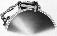
Figure 202 Showing position
of tripping latch housing, operating shaft, and linkage, in
position on barrel and its relation to other mechanisms.
(A) Operating shaft and
linkage; (B) Tripping latch
housing.
108
Figure 203 The tripping latch housing, interior view,
showing tripping latch extending down info the tube in
position to trip starting lever on torpedo. Dotted lines
show position of latch when raised.
the tripping latch as required.
Tripping latch linkages should be examined carefully at regular intervals to make certain that there
is no deformation of any of the parts, also that there
is no lost motion in operation. These linkages should
also be tested carefully for correspondence between
actuation and response, to make certain, for example, that when the tripping latch is raised by the
opening of the breech door it does not project
within the 21.125 inch bore of the tube, in which
case it would interfere with the loading of a mine,
as previously stated; also, that when the tripping
latch is lowered by the closing of the breech door,
it projects into the tube the required amount as
shown by the drawings which apply specifically to
the particular installation in the submarine.
The projection of the tripping latch within the
bore is best tested by the use of the barrel center
line gauge, which is specially fitted to indicate
whether this projection (as well as the projections
of the stop bolt, and depth, speed and gyro setting
spindles) is accurate. Do not close the breech door
with the barrel centerline gauge in place to test the
projection of the tripping latch, since the tripping
latch is forced down by the closing of the breech
door, and the tripping latch linkage will be de
formed if the tripping latch is then prevented by
the barrel centerline gauge from taking its "down"
position.
Figure 204 The starting lever on the torpedo, operator
removing safety stick which protects the starting lever
and prevents it from being tripped accidentally up to the
time the torpedo is loaded into the tube.
THE TORPEDO STOP BOLT
The purpose of the torpedo stop bolt is to fix the
position of the torpedo in the tube so the depth,
gyro, and speed setting sockets in the torpedo will
be in the proper location with reference to the setting mechanisms, so that the spindles of the setting
mechanisms will engage the sockets in the torpedo
readily. It also fixes the position of the starting
lever with relation to the tripping latch.
On the top of the torpedo is a guide stud which
slides in the guide slot in the top land of the interior of the barrel, keeping the torpedo in its proper
position and preventing it from rotating in the tube.
The torpedo stop bolt engages this guide stud as the
torpedo is being slid into the tube.
109
There are two housings for torpedo stop bolts, attached on the top of the middle section of the barrel,
as shown in Figure 18 on page 20, also in the large
fold-out chart between pages 22 and 23. Only one
of these housings is used, however, depending upon
the type of torpedo being used. For torpedoes such
as the Mark 14, or others having a distance of 141.44
inches from the tail to the front of the guide stud,
the housing nearest the muzzle end of the tube will
be used. For torpedoes such as the Mark 10, Modification 3, or others having a distance of 109.0 inches
from the tail to the front of the guide stud, the
housing nearest the breech end of the tube is used.
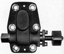
The stop bolt housing, detached from the tube, is
shown in Figure 205, a side view being shown in
Figure 206. In Figure 207, a view of the under
side of the housing, the stop bolt is shown in the
down position, while in Figure 208 the stop bolt
is shown in the up position. Figure 209, in which
the housing has been broken away, shows the interior mechanism and its operation. Figure 210 is
a view of the parts disassembled.
Each of the two housings includes the stop bolt
lever, the stop shaft, and the lever attached to the
stop rod which lifts or retracts the stop bolt at the
time-of-firing. Only one stop bolt, stop bolt gib, and
stop spring are installed, however, these parts being
interchangeable from one housing to the other.
Referring to Figure 207, the stop bolt, as well
as the stop bolt gib, and the stop spring, can easily
be removed from the stop bolt lever and the housing by simply removing the gib screw. Care should
be taken to observe the position of these pieces as
they are removed, so they can be placed in the other
housing in the same order and without difficulty, the
procedure for assembling these parts, or for putting
them in the housing, being the reverse of that for
removing them.
The stop bolt is lifted or retracted from the
tube by means of the stop rod, which is connected
with the lever (A in Figure 207). The stop rod
extends, through a stuffing box, to the retraction
slide (by means of which the stop piston retracts
the gyro setting spindle) which in turn is connected
to the piston of the torpedo stop cylinder (as
in Figure 211, which forms a part of the firing
Figure 205 The torpedo stop bolt housing.
Figure 207 Torpedo stop bolt housing as seen
from underneath, showing (A) Lever to which
stop rod is attached; (B) Stop bolt, in down
position; (C) Stop bolt gib; (D) Gib screw;
(E) Stop shaft; (F) Stop bolt lever.
110
Figure 206 Side view of torpedo stop bolt
housing.
Figure 208 Showing stop bolt in up position.
mechanism, as described in Chapter 5 (see pages
52 and 53). As the firing lever is pressed, opening
the stop cylinder valve and admitting air into
the torpedo stop cylinder, the piston of the torpedo stop cylinder is forced toward the breech end
of the tube, drawing the stop rod with it, thereby
(after first taking up the designed lost motion between the lever A of Figure 207 and the stop shaft
E of Figure 207) lifting or retracting the stop bolt
and disengaging the gyro setting spindle in the
same operation.
As the stop rod is drawn toward the breech end
of the tube it pulls the lever (A in Figure 207),
which is attached to the stop shaft (N in Figure
210). This stop shaft enters the stop bolt housing
through a stuffing box, which must be kept tight to
prevent leakage, yet not so tight that it will prevent
rotation of the shaft and thereby interfere with the
proper operation of the stop bolt.
Figure 209, which shows the interior of the housing, gives a better idea of the operation of the stop
bolt. Studying this with Figure 210, which shows
the parts disassembled, the following steps should be
noted: The stop shaft connects with the stop bolt
lever (Q in Figure 210), the rounded projection at
the end of this lever engaging a slot in the stop
bolt (V in Figure 210).
The action of the stop bolt lever, as the stop rod
is pulled by the piston of the torpedo stop cylinder,
raises the stop bolt vertically, the stop bolt gib (S in
Figure 210) and the shape of the housing acting
as a guide for the vertical movement of the stop bolt.
A lug on the stop bolt gib determines the position
of the bolt when it is down.
The length of the slot in the stop bolt which is
engaged by the rounded end of the stop bolt lever
permits a slight overtravel of the top rod. This
feature is carried over from the tube design as it
existed before the adoption of automatic gyro setting spindle retraction. The overtravel was originally provided so as to allow the stop rod to make
a portion of its stroke without lifting the stop bolt,
in case air pressure should, by leakage or malfunction, come on the stop cylinder while the firing
interlock shutter bar is in position to block the stop
111
Figure 209 Interior view of
torpedo stop bolt housing.
Figure 211 The torpedo stop cylinder, a unit of
the firing mechanism, showing (A) Threads for
connection to gyro setting spindle retraction slide;
(B) Stop rod spring; (C) Electric firing solenoid;
(D) Stop cylinder valve; (E) Firing handle; (F)
Stop cylinder; (G) Pilot valve.
112
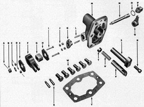
Figure 210 Torpedo stop bolt housing and parts disassembled. (A) Cotter pin; (B) Nut for shaft; (C)
Washer; (D) Castellated nuts with cotter pins; (E)
Lever plate; (F) Lever; (G) Actuating block; (H) Lever
plate; (I) Bolts; (J) Nuts; (K) Gland; (L) Stud bolts;
(M) Housing;, (N) Stop shaft; (O) Washer; (P) Plug;
(Q) Stop bolt lever; (R) Gib screw; (S) Stop bolt gib;
(T) Spring seat; (U) Stop
spring; (V) Stop bolt; (W)
Tap bolts; (X) Taper dowels;
(Y) Gasket.
rod. (In such a case, the end of the stop rod will
engage in a recess in the shutter bar, as explained
in Chapter 4, under "Firing Interlocking Mechanism.") When automatic gyro spindle retraction was
adopted, additional overtravel of the stop piston
extension was considered necessary in order that
the engaging end of the spindle should be clear of
the socket in the torpedo before the stop bolt started
to lift. This additional overtravel is provided by the
clearance between parts F and G in Figure 210.
After a torpedo has been fired, and the air pressure on the piston of the torpedo stop cylinder is
released, the spring on the stop rod where it connects with the piston of the torpedo stop cylinder
(See Figure 211) forces the stop rod back toward
the muzzle end of the tube, and this action of the
stop rod combined with the stop bolt spring (U in
113
Figure 210) allows the stop bolt to drop back into
place to engage the guide stud of the next torpedo
to be loaded into the tube.
The stop bolt has three grooves, two of which
extend the entire length of the bolt. The purpose
of these grooves is to allow free passage of air and
water from the barrel, and thereby prevent any
obstruction to the upward movement of the stop
bolt which might be caused by air and water be
coming trapped in the upper part of the housing.
It is important that the connections between the
stop rod and the lever which operates the stop shaft
to raise the stop bolt be carefully inspected regularly,
and that it be maintained in proper adjustment at
all times. An adjustment spacer is provided for adjusting the stop bolt lever, this spacer being located
at the end of the stop rod proper, where the stop rod
connects with the slide that retracts the gyro setting
spindle, as shown in Figure 212. The adjustment
should be made so that when the stop bolt is all the
way down, in which position its end should be
10.563 inches, plus or minus .015 inch, from the
center line of the barrel, it should not be possible
to push the stop bolt up more than .045 inch before
it contacts the stop bolt lever.
When loading a torpedo into the tube, extreme
care should be taken to ease the torpedo gently
against the stop bolt to avoid bending the stop bolt
or binding any of the parts of the stop bolt assembly.
Should the stop bolt become bent, or in any way
mutilated so it does not function properly, it should
be immediately replaced.
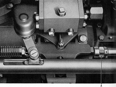
Figure 212 Showing (A) connection on stop rod for adjusting stop bolt lever.